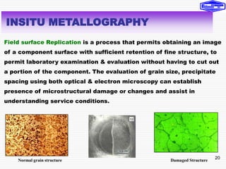
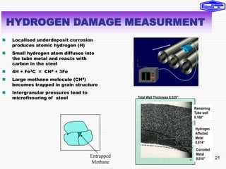
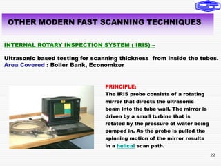
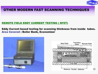
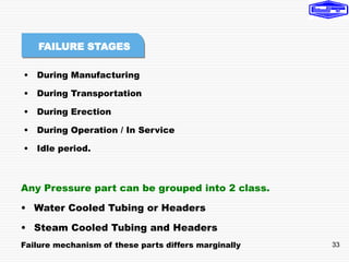
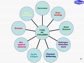
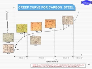
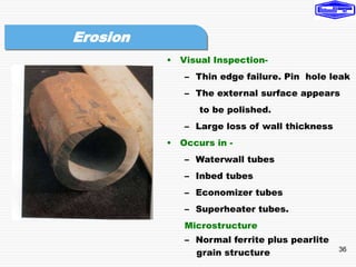
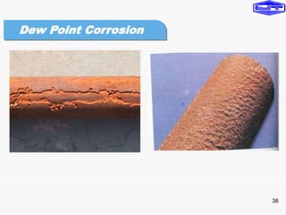
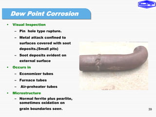
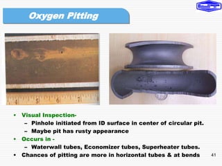
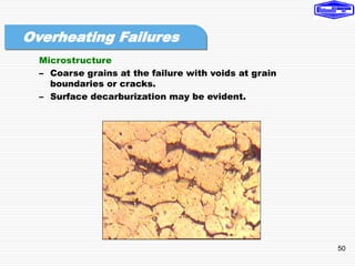
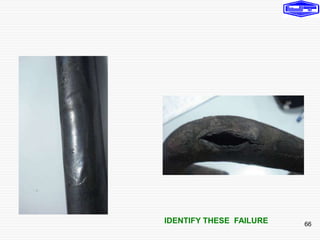
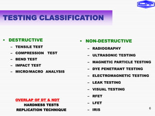
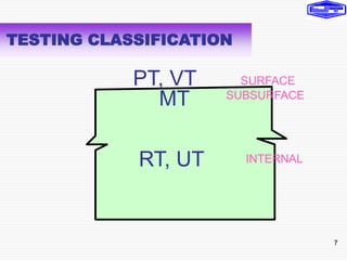
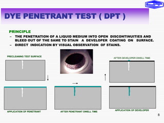
This presentation covers various inspection tests for pressure parts, including visual inspection, thickness measurement, non-destructive testing, and modern equipment. It discusses test classifications like destructive and non-destructive, as well as specific tests like dye penetrant, magnetic particle, ultrasonic, and radiography. The presentation also covers topics like failure analysis, corrosion measurement, and how to properly handle pressure part failures.


![19
TOD
T
Ts
Oxide Scale
t = 0.010” to 0.03”
0.001” scale - 20 F increase in TOD
T
OD
=
20
0
F
to
60
0
F
OXIDE SCALE MEASUREMNT
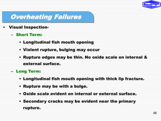
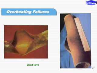
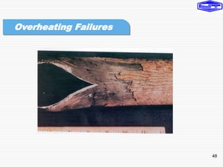
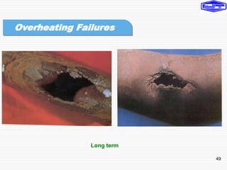
• Tube Temperatures > 900o F
• Failure prone by Creep Fatigue
• Oxide Scale formed (Fe2O3)
• Metal temperature increase 1-2o F
increases creep damage
Creep - Due to thermal
activation, materials can
slowly and continuously
deform even under constant
load (stress) and eventually
fail.
[The time dependent,
thermally assisted
deformation of components
under load (stress)]
Stress Rupture
Corrosion Assisted
Erosion Assisted](https://image.slidesharecdn.com/06-230731070801-97739cce/85/06-Tube-failures-Testing-Equipment-ppt-19-320.jpg)