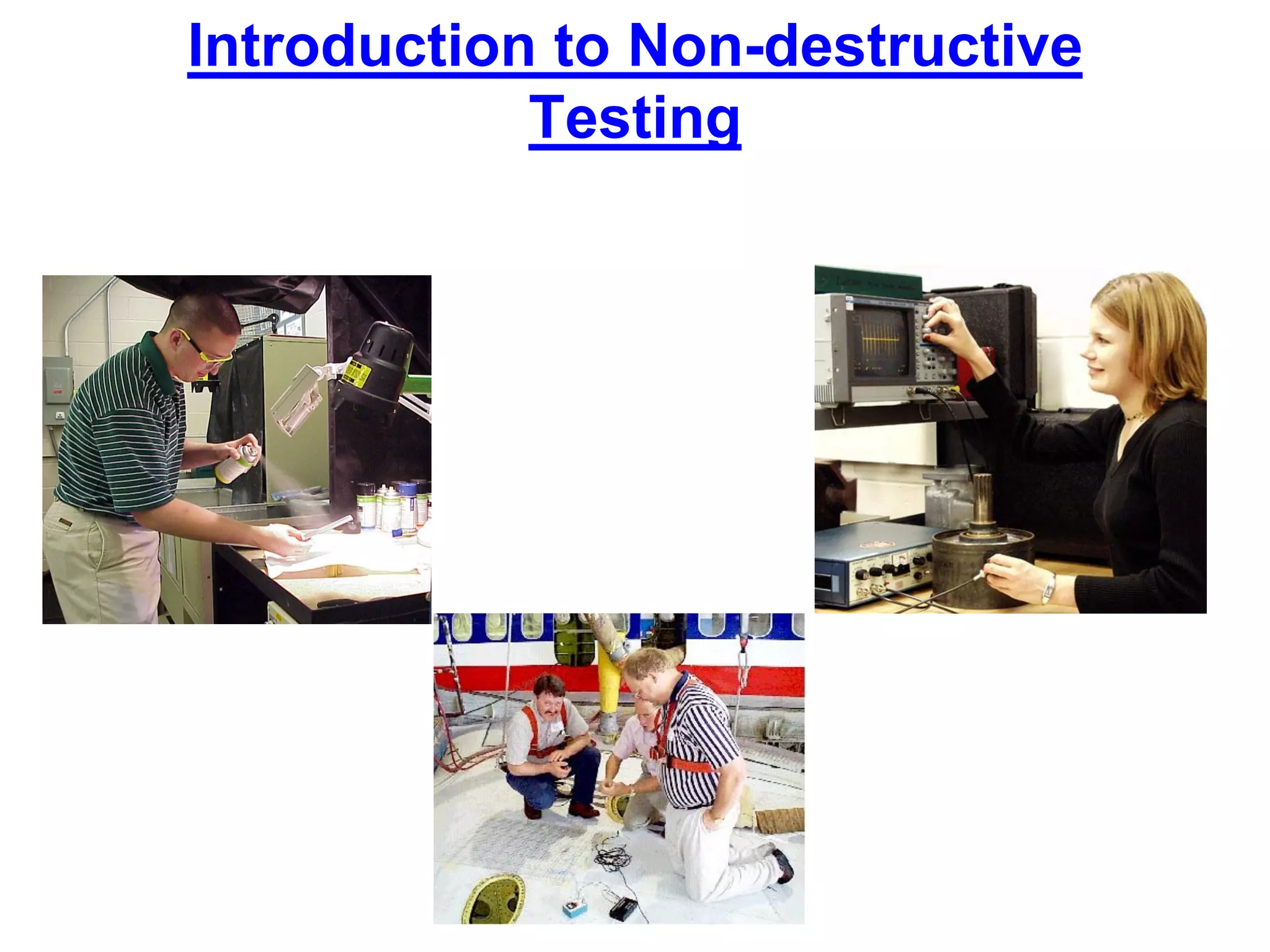
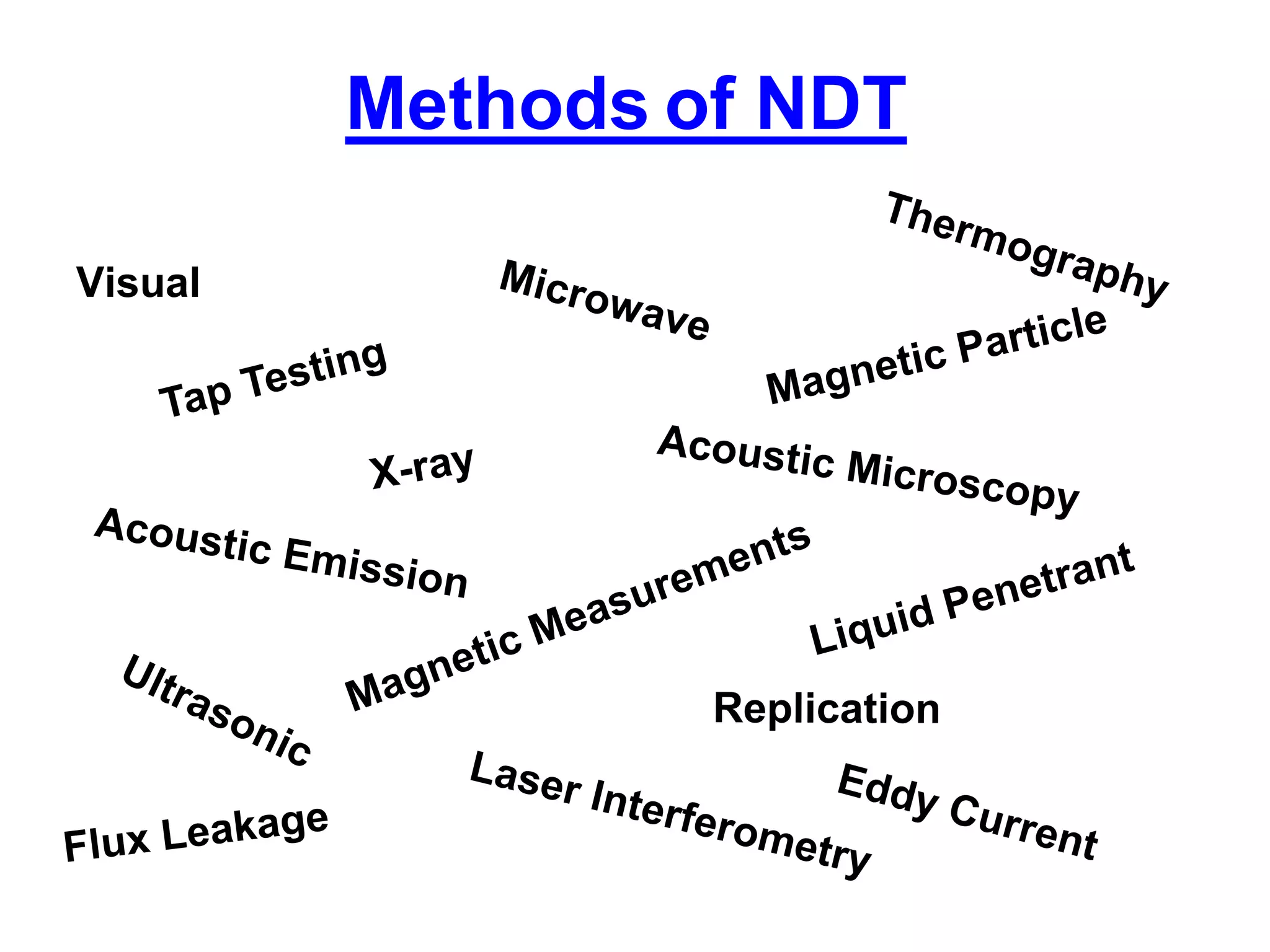
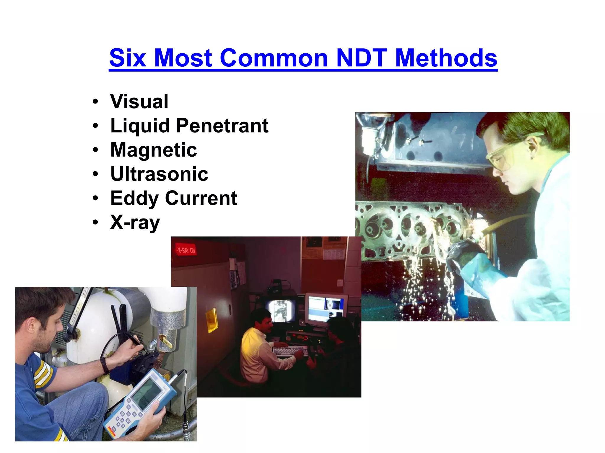
Introduction to the non destructive testing explains the methods for evaluating and verifying many types of Materials as plastics, structures, metals, chemicals, leakage, physical properties. It's very used in the concrete engineering world and in the scientific world.
2. The use of noninvasive
techniques to determine
the integrity of a material,
component or structure
or
quantitatively measure
some characteristic of
an object.
i.e. Inspect or measure without doing harm.
Definition of NDT
4. What are Some Uses of NDE Methods?
• Flaw Detection and Evaluation
• Leak Detection
• Location Determination
• Dimensional Measurements
• Structure and Microstructure
Characterization
• Estimation of Mechanical and
Physical Properties
• Stress (Strain) and Dynamic
Response Measurements
• Material Sorting and Chemical
Composition Determination Fluorescent penetrant indication
5. When are NDE Methods Used?
–To assist in product development
–To screen or sort incoming materials
–To monitor, improve or control
manufacturing processes
–To verify proper processing such as heat
treating
–To verify proper assembly
–To inspect for in-service damage
There are NDE application at almost any stage
in the production or life cycle of a component.
6. Six Most Common NDT Methods
• Visual
• Liquid Penetrant
• Magnetic
• Ultrasonic
• Eddy Current
• X-ray
7. Most basic and common
inspection method.
Tools include
fiberscopes,
borescopes, magnifying
glasses and mirrors.
Robotic crawlers permit
observation in hazardous or
tight areas, such as air
ducts, reactors, pipelines.
Portable video inspection
unit with zoom allows
inspection of large tanks
and vessels, railroad tank
cars, sewer lines.
Visual Inspection
8. • A liquid with high surface wetting characteristics
is applied to the surface of the part and allowed
time to seep into surface breaking defects.
• The excess liquid is removed from the surface
of the part.
• A developer (powder) is applied to pull the
trapped penetrant out the defect and spread it
on the surface where it can be seen.
• Visual inspection is the final step in the
process. The penetrant used is often loaded
with a fluorescent dye and the inspection is
done under UV light to increase test
sensitivity.
Liquid Penetrant Inspection
9. Magnetic Particle Inspection
The part is magnetized. Finely milled iron particles coated with a dye
pigment are then applied to the specimen. These particles are
attracted to magnetic flux leakage fields and will cluster to form an
indication directly over the discontinuity. This indication can be
visually detected under proper lighting conditions.
11. Radiography
The radiation used in radiography
testing is a higher energy (shorter
wavelength) version of the
electromagnetic waves that we
see as visible light. The radiation can
come from an X-ray generator or a
radioactive source.
High Electrical Potential
Electrons
-+
X-ray Generator
or Radioactive
Source Creates
Radiation
Exposure Recording Device
Radiation
Penetrate
the Sample
12. Film Radiography
Top view of developed film
X-ray film
The part is placed between the
radiation source and a piece of film.
The part will stop some of the
radiation. Thicker and more dense
area will stop more of the radiation.
= more exposure
= less exposure
The film darkness
(density) will vary with
the amount of radiation
reaching the film
through the test object.
15. Eddy Current Testing
Eddy current testing is particularly well suited for
detecting surface cracks but can also be used to make
electrical conductivity and coating thickness
measurements. Here a small surface probe is scanned
over the part surface in an attempt to detect a crack.
16. High frequency sound waves are introduced into a
material and they are reflected back from surfaces or
flaws.
Reflected sound energy is displayed versus time, and
inspector can visualize a cross section of the specimen
showing the depth of features that reflect sound.
f
plate
crack
0 2 4 6 8 10
initial
pulse
crack
echo
back surface
echo
Oscilloscope, or flaw
detector screen
Ultrasonic Inspection (Pulse-Echo)
17. Ultrasonic Imaging
Gray scale image produced using
the sound reflected from the front
surface of the coin
Gray scale image produced using the
sound reflected from the back surface
of the coin (inspected from “heads” side)
High resolution images can be produced by plotting
signal strength or time-of-flight using a computer-
controlled scanning system.
18. Common Application of NDT
• Inspection of Raw Products
• Inspection Following
Secondary Processing
• In-Services Damage
Inspection
22. Power Plant Inspection
Probe
Signals produced
by various
amounts of
corrosion
thinning.
Periodically, power plants are
shutdown for inspection.
Inspectors feed eddy current
probes into heat exchanger
tubes to check for corrosion
damage.
Pipe with damage
23. Wire Rope Inspection
Electromagnetic devices
and visual inspections are
used to find broken wires
and other damage to the
wire rope that is used in
chairlifts, cranes and other
lifting devices.
24. Storage Tank Inspection
Robotic crawlers
use ultrasound to
inspect the walls of
large above ground
tanks for signs of
thinning due to
corrosion.
Cameras on
long
articulating
arms are used
to inspect
underground
storage tanks
for damage.
25. Aircraft Inspection
• Nondestructive testing is used
extensively during the
manufacturing of aircraft.
• NDT is also used to find cracks
and corrosion damage during
operation of the aircraft.
• A fatigue crack that started at
the site of a lightning strike is
shown below.
26. Jet Engine Inspection
• Aircraft engines are overhauled
after being in service for a period
of time.
• They are completely disassembled,
cleaned, inspected and then
reassembled.
• Fluorescent penetrant inspection
is used to check many of the parts
for cracking.
27. Sioux City, Iowa, July 19, 1989
A defect that went
undetected in an
engine disk was
responsible for
the crash of
United Flight 232.
Crash of United Flight 232
28. Pressure Vessel Inspection
The failure of a pressure vessel
can result in the rapid release of
a large amount of energy. To
protect against this dangerous
event, the tanks are inspected
using radiography and
ultrasonic testing.
29. Rail Inspection
Special cars are used to
inspect thousands of miles
of rail to find cracks that
could lead to a derailment.
30. Bridge Inspection
• The US has 578,000
highway bridges.
• Corrosion, cracking and
other damage can all
affect a bridge’s
performance.
• The collapse of the Silver
Bridge in 1967 resulted in
loss of 47 lives.
• Bridges get a visual
inspection about every 2
years.
• Some bridges are fitted
with acoustic emission
sensors that “listen” for
sounds of cracks growing.
31. NDT is used to inspect pipelines
to prevent leaks that could
damage the environment. Visual
inspection, radiography and
electromagnetic testing are some
of the NDT methods used.
Remote visual inspection using
a robotic crawler.
Radiography of weld joints.
Magnetic flux leakage inspection.
This device, known as a pig, is
placed in the pipeline and collects
data on the condition of the pipe as it
is pushed along by whatever is being
transported.
Pipeline Inspection
32. Special Measurements
Boeing employees in Philadelphia were given the privilege of
evaluating the Liberty Bell for damage using NDT techniques. Eddy
current methods were used to measure the electrical conductivity of
the Bell's bronze casing at various points to evaluate its uniformity.
33. RADIOGRAPHY
Sub assembly Components:
The sub assembly coach components
fabricated by fillet welding are taken
radiographs, where the load acting
areas as prescribed by the relevant
drawing and suspected weld area during
visual inspection.
38. RADIOGRAPHIC STANDARDS FOR
EVALUATION OF WELD DEFECTS.
• 1. IIW Standard:
THERE ARE FIVE IIW STANDARDS
– BLACK DEFECT FREE
– BLUE VERY SLIGHT IMPERFECTIONS AS
REGARDS HOMOGENITY IN THE FORM OF ONE
OR MORE OF THE FOLLOWING DEFECT GAS
CAVITY, SHRINKAGE CAVITY, SLAG INCLUTION
AND UNDER CUT.
Two type of standards are generally used for evaluation
1. IIW standard
2. ASTM standard
39. IIW RADIOGRAPHIC STANDARDS FOR
EVALUATION OF WELD DEFECTS.
– GREEN SLIGHT IMPERFECTIONS AS REGARDS
HOMOGENITY IN THE FORM OF ONE OR MORE OF THE
FOLLOWING DEFECT GAS CAVITY, SHRINKAGE CAVITY, SLAG
INCLUSION, UNDER CUT AND INCOMPLETE PENETRATION.
– BROWNMARKED IMPERFECTIONS AS REGARDS
HOMOGENITY IN THE FORM OF ONE OR MORE OF THE
FOLLOWING DEFECT GAS CAVITY, SHRINKAGE CAVITY, SLAG
INCLUSION, UNDER CUT, INCOMPLETE PENETRATION AND
FUSION DEFECT.
40. RADIOGRAPHIC STANDARDS FOR
EVALUATION OF WELD DEFECTS.
– RED GROSS IMPERFECTIONS AS REGARDS
HOMOGENITY IN THE FORM OF ONE OR MORE OF
THE FOLLOWING DEFECT GAS CAVITY,
SHRINKAGE CAVITY, SLAG INCLUTION, UNDER
CUT, INCOMPLETE PENETRATION, FUSION DEFECT
AND CRACK
IIW BLUE STANDARD IS FOLLOWED AT ICF WITH
ACCEPTANCE CRITERIA TO ICF SPECIFICATION
NO.ICF/M&C/SPEC/010
41. RADIOGRAPHIC STANDARDS FOR
EVALUATION OF WELD DEFECTS.
RCF is using ASTM Standards for Radiographic
evaluation.
• Specified Welding defects level as per ASTM E- 390 Vol-II
– Shrinkage /Crack of any kind are not allowed
– Lack of Fusion is not allowed
– Incomplete Penetration is allowed up to level-II
– Burn through is not allowed
– Undercut is allowed upto level-IV
– Slag Inclusion is allowed up to Level-III
– Porosity
» Coarsed scattered Porosity is allowed upto level-II
» Fine scattered Porosity is allowed up to Level-IV
» Cluster Porosity is allowed up to Level-III
» Elongated Porosity is not allowed
42. RADIOGRAPHIC STANDARDS FOR
EVALUATION OF CAST DEFECTS
• Specified Casting defects level as
per ASTM E- 446
– The castings should be significantly
free from harmful casting defects like :
» Shrinkage /Crack
» Sand and Slag inclusions
» Gas porosity or blow holes etc
43. For More Information on NDT
The Collaboration for
NDT Education
www.ndt-ed.org
The American Society
for Nondestructive
Testing
www.asnt.org