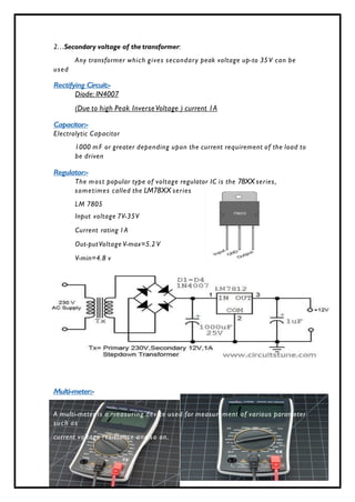
This industrial training report focuses on embedded systems, detailing their specific applications and components, such as microcontrollers and various electronic parts including resistors and capacitors. It includes practical training content related to PCB design, interfacing with the ATmega8 microcontroller, as well as motor driver circuits and temperature sensors. The document aims to fulfill academic requirements for a Bachelor of Technology degree in Electronics and Communication Engineering.

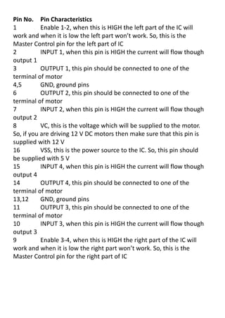
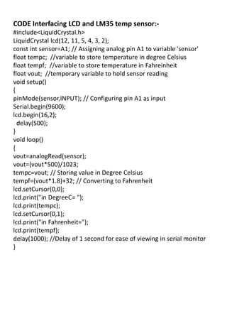
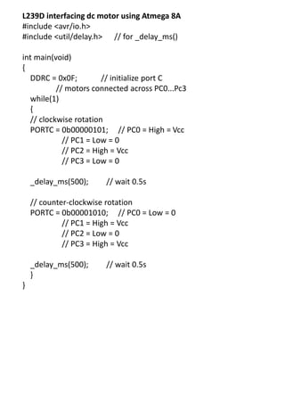
![2. Power dissipation
Low power resistor have maximum power rating less than 5 watts ,
cylindrical in shape
High power resistors are those with maximum power rating higher than 5
watts and always comes with a heat sink
P =Vrms2
/R
4k9 means 4900ohm
If the supply voltage is 12 volts, then maximum possible power is
calculated using V2
/R - which [(12 * 12 )/330 ]= 0.435 watts.
RESISTOR SYMBOLS:-
Capacitor symbols:-
Page 3 of 3](https://image.slidesharecdn.com/industrialtrainingreportonembeddeds-241125040340-0af64307/85/INDUSTRIAL_TRAINING_REPORT_ON_EMBEDDED_S-pdf-3-320.jpg)
![Embedded System[586]](https://cdn.slidesharecdn.com/ss_thumbnails/viisemesterindustrialtrainingreportpawan586-171104035355-thumbnail.jpg?width=640&height=640&fit=bounds)


![[IJET-V2I3P18] Authors: Mr. B. N. Patil , Mr. Sandesh Sonar , Mr. Pavankumar ...](https://cdn.slidesharecdn.com/ss_thumbnails/ijet-v2i3p18-160711111028-thumbnail.jpg?width=640&height=640&fit=bounds)


