IJRET : International Journal of Research in Engineering and Technology is an international peer reviewed, online journal published by eSAT Publishing House for the enhancement of research in various disciplines of Engineering and Technology. The aim and scope of the journal is to provide an academic medium and an important reference for the advancement and dissemination of research results that support high-level learning, teaching and research in the fields of Engineering and Technology. We bring together Scientists, Academician, Field Engineers, Scholars and Students of related fields of Engineering and Technology.
Digital Signal Controller Based Four Switch Three Phase Inverter Fed BLDC Mot...ijsrd.com
Brushless Direct Current Motors (BLDC) are used in many applications for their low cost, high performance , ease of control, less maintenance because of absence of commutators and brushes and high efficiency. These advantages of BLDC motors have led to their wide spread use in variable speed drives. The main objective of this paper is to develop a drive system for BLDC motor with reduced switches and minimum hardware. The proposed work is based on, the dsPIC controlled four switch three phase inverter fed BLDC motor drive. The advantage of this inverter that uses four switches instead of conventional six switches is lesser switching losses, lower electromagnetic interference (EMI), less complexity and reduced interference circuit. dsPIC30F4011 digital controller is used to generate the switching pulses for Four Switch Three Phase Inverter consists of MOSFET Switches to drive the BLDC motor. Simulation and experimental work are carried out and results are presented. A simulation is carried out using MATLAB/SIMULINK and in the experimental work a prototype model is constructed to verify the simulation results.
Three-phase ac motors have been the workhorse of industry since the earliest days of electrical engineering. They are reliable, efficient, cost-effective and need little or no maintenance. In addition, ac motors such as induction and reluctance motors need no electrical connection to the rotor, so can easily be made flameproof for use in hazardous environments such as in mines.
In order to provide proper speed control of an ac motor, it is necessary to supply the motor with a three phase supply of which both the voltage and the frequency can be varied. Such a supply will create a variable speed rotating field in the stator that will allow the rotor to rotate at the required speed with low slip. This ac motor drive can efficiently provide full torque from zero speed to full speed, can overspeed if necessary, and can, by changing phase rotation, easily provide bi-directional operation of the motor. A drive with these characteristics is known as a PWM (Pulse Width Modulated) motor drive.
Drives and motors are an integral part of industrial equipment from packaging,robotics, computer numerical control (CNC), machine tools, industrial pumps,and fans. Designing next-generation drive systems to lower operating costs requires complex control algorithms at very low latencies as well as a flexibleplatform to support changing needs and the ability to design multiple-axis systems.
Traditional drive systems based on ASICs, digital signal processors (DSPs), and microcontroller units lack the performance and flexibility to address these needs. Altera’s family of FPGAs provides a scalable platform that can be used to offload control algorithm elements in hardware. You may also integrate the whole drive system with industry-proven processor architectures while supporting multipletypes of encoders and industrial Ethernet protocols. This “drive on a chip” system reduces cost and simplifies development.
Speed Control of Brushless Dc Motor Using Fuzzy Logic Controlleriosrjce
This paper presents a control scheme of a fuzzy logic for the brushless direct current (BLDC)
permanent magnet motor drives. The mathematical model of BLDC motor and fuzzy logic algorithm is derived.
The controller is designed to tracks variations of speed references and stabilizes the output speed during load
variations. The BLDC has some advantages compare to the others type of motors, however the nonlinearity of
the BLDC motor drive characteristics, because it is difficult to handle by using conventional proportionalintegral
(PI) controller. The BLDC motor is fed from the inverter where the rotor position and current
controller is the input. In order to overcome this main problem, the fuzzy logic control is learned continuously
and gradually becomes the main effective control. The effectiveness of the proposed method is verified by
develop simulation model in MATLAB-Simulink program. The simulation results show that the proposed fuzzy
logic controller (FLC) produce significant improvement control performance compare to the PI controller for
both condition controlling speed reference variations and load disturbance variations. Fuzzy logic is introduced
in order to suppressing the chattering and enhancing the robustness of the controlled system. Fuzzy boundary
layer is developed to provide smother transition to the equivalent control. Smaller overshoot in the speed
response and much better disturbance rejecting capabilities.
The following resources come from the 2009/10 BEng in Digital Systems and Computer Engineering (course number 2ELE0065) from the University of Hertfordshire. All the mini projects are designed as level two modules of the undergraduate programmes.
The objectives of this project are to design, develop and test software for an embedded system that will smoothly control the rotation of a stepper motor, taking into account the physical constraints on the maximum operating speed of the motor.
Each student will be required to design a ‘C’ program can rotate a stepper motor to a number of user-defined positions as quickly as possible. This will include sensing of the marker pulse, the implementation of an appropriate speed profile and the use of timer-generated interrupts.
This project is used to control the speed of brushless DC motor by using arduino development board with rpm display and pulse width modulation. It can be used in different industrial applications.
BIDIRECTIONAL SPEED CONTROL OF DC MOTOR USING 8051 MICROCONTROLLERShanmukha S. Potti
1. This project deals with bidirectional speed control of DC motor using 8051 micro-controller.
2. Design of H bridge dc-dc converter is an IGBT based bridge circuit.
3. The control circuit consists of the 8051 microcontroller which is programmed to generate pulses to turn on IGBTs per required sequence.
4. The H bridge dc-dc converter is implemented with hardware setup and software program in the 8051 –C code.
Motor Control Relay, Pwm, DC and Stepper MotorsDevashish Raval
In this presentation, a brief introduction of relay, optoisolaters, interfacing and working of stepper motor and DC motor is given.
The contents are referred from the book of mazidi.
DC Motor Direction Control Using 8051 C ProgramDinesh Damodar
this ppt illustrates the interfacing of 8051 microcontrollers and DC motor. Here we had undertaken Simple geared DC motor as a subject to control, using 8051. 8051 is considered since it is an entrance of basics in learning microcontrollers
Stepper Motor Drive For Position Control in Robotic Applicationsijiert bestjournal
This project is about making an embedded system in order to control different functionalities of a stepper motor. The main functi ons of this stepper motor are to control the speed and direction. This system will actually adapt the requirements o f the modern technology. With the help of this system one can control the speed of th e stepper motor controller for pick and place robot which is used in material hand ling in various industries.
FOUR QUADRANT SPEED CONTROL OF DC MOTOR USING AT89S52 MICROCONTROLLERJournal For Research
Speed control of a machine is the most vital and important part in any industrial organization. This paper is designed to develop a four quadrant speed control system for a DC motor using microcontroller. The motor is operated in four quadrants i.e. clockwise, counter clock-wise, forward brake and reverse brake. It also has a feature of speed control. The four quadrant operation of the dc motor is best suited for industries where motors are used and as per requirement they can rotate in clockwise, counter-clockwise and also apply brakes immediately in both the directions. In case of a specific operation in industrial environment, the motor needs to be stopped immediately. In such scenario, this proposed system is very apt as forward brake and reverse brake are its integral features. Instantaneous brake in both the directions happens as a result of applying a reverse voltage across the running motor for a brief period and the speed control of the motor can be achieved with the PWM pulses generated by the microcontroller. The microcontroller used in this project is from 8051 family. Push buttons are provided for the operation of the motor which are interfaced to the microcontroller that provides an input signal to it and controls the speed of the motor through a motor driver IC. The speed and direction of DC motor has been observed on digital CRO. Microcontroller programming has been written in assembly language by using notepad and it has been converted in hex file by using micro vision Kiel. The burning of programming in the 8051 microcontroller chip has been done by using positron boot loader software.
DC MOTOR SPEED CONTROL USING ON-OFF CONTROLLER BY PIC16F877A MICROCONTROLLERTridib Bose
This presentation consists the speed control of a dc motor using hardware (microcontroller) by changing the reference voltages logically and minimising errors.
Bi directional speed control of dc motor and stepper motor through mat lab us...eSAT Journals
Abstract In any industry speed control of an electric drive system is very critical and crucial. Every designer aims at achieving a control methodology having high degree of precision. But industry needs are ever evolving in nature. Hence it is very much essential that along with conventional speed control mechanisms we must also have simple interactive graphical based control strategies. Several algorithms/methodologies have been developed over the years to achieve speed control of motors. In this context by encompassing the usability of Mat Lab, work has been done to control the speed of stepper motor and DC motor using microcontroller. Microcontroller is programmed to achieve bi directional speed control. The main objective of this work is to develop the graphical user interface of motor control through mat Lab guide and the interface of the same with hardware via serial communication. PIC is used as the controller. Keywords— DC, PIC, μC, AC, GUI, IC
2. 1 | P a g e
Group Members:
Hasan Iqbal Baig
M Noraiz
Muneer Ahmad
Waqar Shaukat
Amir Saleem
3. 2 | P a g e
Contents
Abstract:...................................................................................................................................................................................3
Introduction: ..........................................................................................................................................................................4
Background: ...........................................................................................................................................................................4
H-bridge:.............................................................................................................................................................................6
Logic toggle:......................................................................................................................................................................7
Procedure:...............................................................................................................................................................................7
Flow Chart:.......................................................................................................................................................................10
Results:...................................................................................................................................................................................11
Conclusion: ...........................................................................................................................................................................13
References: ...........................................................................................................................................................................13
Appendix:..............................................................................................................................................................................14
4. 3 | P a g e
Abstract:
This report deals with the working of the bi-directional motor working and the implementation of it. The
task was to show the duty cycle with the three speeds and time on the LCD. The coding of the report
is shown in the appendix while the results shows the complete working of it in both the directions.
Hence this report also covers the aspect of working of H-bridge and toggle circuit.
5. 4 | P a g e
Introduction:
A micro-controller is defined as a small stand-alone computer, which is capable of executing
commands in series as well as parallel. It perform pre-programmed tasks and interacts with other
hardware devices. Being packed, in a tiny integrated circuit (IC) whose size and weight is usually
negligible, it is becoming the perfect controller for robots or any machines to perform some kind of
intelligent automation. A single microcontroller can be sufficient to control a small mobile robot, an
automatic washer machine or a security system. Apart from this, a microcontroller also possesses a
memory place to store the program which is to be executed, and a number of input/output lines that
are used to interact with other devices.
Microcontrollers are so cheap and easily available that now-a-days it is used to simplify logic circuits
with a sole purpose of attaining some design flexibility and saving memory. Apart from that, some
machines and robots even relies on a number of microcontrollers, each microcontroller is asked to
perform a certain task. Most recent microcontrollers are ‘In System Programmable’, means in it, you
can modify the program which is to be executed, without removing the microcontroller from its place.
Background:
Microcontroller is different from microprocessor because microcontroller has internally linked input
output ports and memory storage elements like register, timer etc. In microprocessor we have to
configure all inputs outputs and memory storage elements externally. Microcontroller is cheaper than
microprocessor.
Block diagram of microcontroller is shown in fig
[1]
Figure 1 Block Diagram Of Microcontroller
It consists of four input as well as four output ports like port 0, port 1, port 2 and port 3. All ports have
8 pins which can be represented by p0.1, p0.2 etc. We can configure all inputs pin as output pin by
initializing all pins with zero and can also use all pins one by one as input or output.
6. 5 | P a g e
As you can see there are two types of memories; one is RAM and other one is EEPROM flash. Ram
is used during programme execution for storage of variable for short time and EEPROM is used for
writing the programme.
The internal memory of 8051 microcontroller has 4kb ROM and 128 Byte Ram. Whereas, the internal
memory contains 128 bytes of RAM i-e 00h and 7 Eh. The Ram is divided into three parts:
4 Rag bank ooh to 1Fh
16 bytes bit addressable RAM 20h to 2Fh
Scratch pad RAM
Similarly, the register Bank has four registers, which each bank carrying eight registers.
bank 0=Ro to R7
bank 1= Ro to R7
bank 2= Ro to R7
bank 3= Ro to R7[2]
[2]
Figure 2 Pin configuration of 8051
After understanding the micrcontroller working, lets discuss the working of DC motor as well.
A DC Motor is an electrical machine which converts electrical energy into mechanical energy. It needs
5 to 12 volts to run its speed which is directly proportional to the applied voltage.
7. 6 | P a g e
[3]
Figure 3 DC Motor.
The input of a DC motor is current/voltage and its output is torque (speed). The working of DC motor
is explained below:
The piece connected to the ground is called the stator and the piece connected to the output shaft is
called the rotor. The inputs of the motor are connected with two wires and by applying a voltage across
them, the motor rotates. The torque of a motor is generated by a current carrying conductor in a
magnetic field. The right hand rule states that if you point your right hand fingers along the direction of
current, I, and curl them towards the direction of the magnetic flux, B, the direction of force is along the
thumb.
[4]
Figure 4 DC Motor Working
H-bridge:
L293D is basically H-bridge IC. It is used for deriving the motor. It can drive the motor in both
clockwise and counter clockwise direction. Basically it is an electronic that enables a voltage to be
applied across a load in either direction.
8. 7 | P a g e
For making the H-bridge, we use the series of relays from relay board. A solid state H bridge is
typically constructed using opposite polarity devices, such as PNP BJTs or P-
channel MOSFETS connected to the high voltage bus and NPN BJTs or N-channel MOSFETs
connected to the low voltage bus.
A common use of the H-bridge is an inverter. The arrangement is sometimes known as a single-
phase bridge inverter.
The H-bridge with a DC supply will generate a square wave voltage waveform across the load. For a
purely inductive load, the current waveform would be a triangle wave, with its peak depending on the
inductance, switching frequency, and input voltage.
[5]
Figure 5 H-bridge Pin Configuration
Logic toggle:
Logic toggle is used as a switch for on and off. We used all these as a switch. On logic toggle there 1
shows to 5V and zero shows to zero volt.
Procedure:
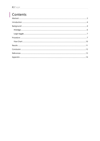
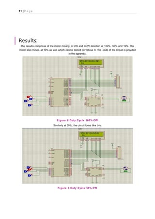
In this project we have to use 8051 for controlling speed of bidirectional motor .We have to show three
different speeds on LCD and we have to drive motor in clockwise as well as anticlockwise direction.
First of all we are using H-bridge with the microcontroller attached. The H-bridge is used to rotate the
motor in both directions i-e CW and CCW.
9. 8 | P a g e
[6]
Figure 6 H-bridge Working
When we apply voltage on forward input i.e. by giving 1 through logic state then transistor Q-1 and Q-
3 on and transistor Q-2 and Q-4 off and motor will move in clockwise direction.
Similarly in case of reverse input when we apply voltage on reverse input i.e. by giving 1 through logic
state resulting the motor will move in anticlockwise direction and transistor Q-2 and Q-4 on and
transistor Q-1 and Q-3 off.
But in third case we come to assume that when we apply voltage in both directions i.e. by setting bit
high through logic state. Eventually the motor will turn off because we are applying the same voltages
in both directions hence resulting it cancels the effect and there is no difference of voltage being
created hence the motor will turn off.
[7]
Figure 7 H-bridge Topology
Logic toggle provides two bits i-e 0 and 1 for ON/OFF and works as a switch. Three logic toggles are
used for three different speed, one logic toggles is used to invert the direction of speed i-e to move
the motor in CW and CCW.
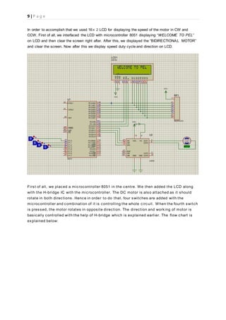
Logic toggle 1 --------------- 100% speed and duty-cycle.
Logic toggle 2 --------------- 50% speed and duty-cycle
Logic toggle 3 --------------- 10% speed and duty-cycle
Logic toggle 4--------------- CW/CCW direction.
10. 9 | P a g e
In order to accomplish that we used 16× 2 LCD for displaying the speed of the motor in CW and
CCW. First of all, we interfaced the LCD with microcontroller 8051 displaying “WELCOME TO PEL’’
on LCD and then clear the screen right after. After this, we displayed the “BIDIRECTIONAL MOTOR’’
and clear the screen. Now after this we display speed duty cycle and direction on LCD.
First of all, we placed a microcontroller 8051 in the centre. We then added the LCD along
with the H-bridge IC with the microcontroller. The DC motor is also attached as it should
rotate in both directions. Hence in order to do that, four switches are added with the
microcontroller and combination of it is controlling the whole circuit. When the fourth switch
is pressed, the motor rotates in opposite direction. The direction and working of motor is
basically controlled with the help of H-bridge which is explained earlier. The flow chart is
explained below:
11. 10 | P a g e
Flow Chart:
Welcome to PEL
When Switch 1 is
active high,
SPD, DCYCLE = 100%
CW
Bi-Directional
Motor
When Switch 2 is
active high,
SPD, DCYCLE = 50%
CW
When Switch 3 is
active high,
SPD, DCYCLE = 10%
CW
When Switch 1 is
active high,
SPD, DCYCLE = 100%
CCW
When Switch 2 is
active high,
SPD, DCYCLE = 50%
CCW
When Switch 3 is
active high,
SPD, DCYCLE = 10%
CCW
Otherwise
SPD, DCYCLE = 0%
STOP
Enable = 0Enable = 1
12. 11 | P a g e
Results:
The results comprises of the motor moving in CW and CCW direction at 100%, 50% and 10%. The
motor also moves at 10% as well which can be tested in Proteus 8. The code of the circuit is provided
in the appendix.
Figure 8 Duty Cycle 100% CW
Similarly at 50%, the circuit looks like this:
Figure 9 Duty Cycle 50% CW
13. 12 | P a g e
Similarly for 10%, the circuit looks like this:
Figure 10 Duty Cycle 10% CW
Similarly, the motor also moves in the bi-directional motor which is also shown below:
Figure 11 Duty Cycle 100% CCW
14. 13 | P a g e
Last but not the least, the motor moving with 50% duty cycle is represented by:
Figure 12 Duty Cycle 50% CCW
Conclusion:
Thus making long story short, this report provides the basic understanding of the working of the bi-
directional motor. Moreover it also helps to understand the working of microcontrollers which is quite
essential in the industry. So summarising it, it was a healthy session with great experience and a lot of
learning.
References:
[1]2016. [Online]. Available: http://www.keil.com/dd/docs/datashts/atmel/at89s51_ds.pdf.
[Accessed: 24- Jun- 2016].
[2]S. patel, "8051 microcontroller Block diagram and pin diagram of 8051 microcontroller with
description. | 8051 Microcontroller", Microcontrollergarden.blogspot.com, 2016. [Online]. Available:
https://microcontrollergarden.blogspot.com/2013/08/block-diagram-and-pin-diagram-of-
8051.html. [Accessed: 24- Jun- 2016].
[3]"DC Motor Control using AVR MCUs - eXtreme Electronics", eXtreme Electronics, 2008. [Online].
Available: http://extremeelectronics.co.in/avr-tutorials/dc-motor-control/. [Accessed: 24- Jun-
2016].
[4]"Theory on DC motors", Mechatronics.mech.northwestern.edu, 2016. [Online]. Available:
http://mechatronics.mech.northwestern.edu/design_ref/actuators/motor_theory.html. [Accessed:
24- Jun- 2016].
15. 14 | P a g e
[5]L. IC and M. Gaber, "EEEC Blog: L293D Motor Driver IC", Eeec2.blogspot.com, 2012. [Online].
Available: http://eeec2.blogspot.com/2012/11/l293d-motor-driver-ic.html. [Accessed: 24- Jun-
2016].
[6]"H Bridge with 4 NPN transistors (tip3055) using a 12v | Electronics and Electrical Engineering
Design Forum | EEWeb Community", Eeweb.com, 2016. [Online]. Available:
https://www.eeweb.com/electronics-forum/h-bridge-with-4-npn-transistors-tip3055-using-a-12v.
[Accessed: 24- Jun- 2016].
[7]"Spring2012 Final Report-Jingjing & Liye - Robotic Mobile Chair", Wiki.cs.mtholyoke.edu, 2016.
[Online]. Available:
http://wiki.cs.mtholyoke.edu/mediawiki/rmc/index.php/Spring2012_Final_Report-
Jingjing_%26_Liye. [Accessed: 24- Jun- 2016].
Appendix:
ACALL DISPLAYLCD
;.......................................BI DIRECTIONAL MOTOR.........
MOV A, #01H ; CLR SCREEN
ACALL Comwrt ; write command
ACALL Delay ; wait for LCD
MOV A, #'B' ; display B
ACALL Datwrt ; write data
ACALL Delay ; wait for LCD
MOV A, #'I' ; display I
ACALL Datwrt ; write data
ACALL Delay ; wait for LCD
MOV A, #'D' ; display D
16. 15 | P a g e
ACALL Datwrt ; write data
ACALL Delay ; wait for LCD
MOV A, #'I' ; display I
ACALL Datwrt ; write data
ACALL Delay ; wait for LCD
MOV A, #'R' ; display R
ACALL Datwrt ; write data
ACALL Delay ; wait for LCD
MOV A, #'E' ; display E
ACALL Datwrt ; write data
ACALL Delay ; wait for LCD
MOV A, #'C' ; display O
ACALL Datwrt ; write data
ACALL Delay ; wait for LCD
MOV A, #'T' ; display T
ACALL Datwrt ; write data
ACALL Delay ; wait for LCD
MOV A, #'I' ; display O
ACALL Datwrt ; write data
ACALL Delay ; wait for LCD
17. 16 | P a g e
MOV A, #'O' ; display O
ACALL Datwrt ; write data
ACALL Delay ; wait for LCD
MOV A, #'N' ; display O
ACALL Datwrt ; write data
ACALL Delay ; wait for LCD
MOV A, #'A' ; display A
ACALL Datwrt ; write data
ACALL Delay ; wait for LCD
MOV A, #'L' ; display L
ACALL Datwrt ; write data
ACALL Delay ; wait for LCD
MOV A, #0C1H; 2nd line position 1
ACALL Comwrt ; write command
ACALL Delay ; wait for LCD
MOV A, #'M' ; display M
ACALL Datwrt ; write data
ACALL Delay ; wait fo
MOV A, #'O' ; display O
ACALL Datwrt ; write data
ACALL Delay ; wait for LCD
18. 17 | P a g e
MOV A, #'T' ; display T
ACALL Datwrt ; write data
ACALL Delay ; wait for LCD
MOV A, #'O' ; display O
ACALL Datwrt ; write data
ACALL Delay ; wait for LCD
MOV A, #'R' ; display R
ACALL Datwrt ; write data
ACALL Delay ; wait for LCD
ACALL DELAY
ACALL DELAY
ACALL DELAY
;......................................... MOTOR CODE ....................
SETB P2.5 ; ENABLE THE PIN OF L293D IC
MOV P1,#00H ;CONFIGURE AS INPUT PORT
AGAIN:
MOV A,P1
CJNE A,#01,SPD1 ;FOR COMPARISON
SETB P2.3 ; FOR DRIVING THE MOTOR IN CLOCKWISE DIRECTION 100%
speed
CLR P2.4
ACALL DISPLAY1 ; FOR DISPLAY THE SPEED AND DUTY CYCLE
ACALL PERCENTAGE1 ;
ACALL DIRECTION1 ; FOR DIRECTION of motor
19. 18 | P a g e
SJMP AGAIN
SPD1:
CJNE A,#02,SPD2 for 2nd speed
MOV TMOD,#01H ;Load TMOD
MOV TL0, #00H ;Load low byte
MOV TH0, #0FFH ;Load high byte
CPL P2.3 ; for driving motor for 50% speed
CLR P2.4
SETB TR0 ;Start Timer 0
again1: JNB TF0, again1 ;Check TF flag
CLR TR0 ;Stop Timer 0
CLR TF0 ;Clear TF flag
ACALL DISPLAY1
ACALL PERCENTAGE2
ACALL DIRECTION1
SJMP AGAIN
SPD2: ;for driving the motor 10% speed
CJNE A,#04,SPD3 ; speed
MOV TMOD,#01H ;Load TMOD
MOV TL0, #00H ;Load low byte
MOV TH0, #00H ;Load high byte
SETB P2.3
CLR P2.4 ;Toggle P1.5
20. 19 | P a g e
SETB TR0 ;Start Timer 0
again2: JNB TF0, again2 ;Check TF flag
CLR TR0 ;Stop Timer 0
CLR TF0 ;Clear TF flag
MOV TMOD,#01H ;Load TMOD
MOV TL0, #0FH ;Load low byte
MOV TH0, #0FFH ;Load high byte
CLR P2.3
CLR P2.4 ;Toggle P1.5
SETB TR0 ;Start Timer 0
again3: JNB TF0, again3 ;Check TF flag
CLR TR0 ;Stop Timer 0
CLR TF0 ;Clear TF flag
ACALL DISPLAY1
ACALL PERCENTAGE3
ACALL DIRECTION1
SJMP AGAIN
;..................FOR COUNTER CLOCKWISE DIRECTON.............
SPD3:
21. 20 | P a g e
CJNE A,#09,SPD4 ;for 100% speed and duty cycle
SETB P2.4
CLR P2.3
ACALL DISPLAY1
ACALL PERCENTAGE1
ACALL DIRECTION2
SJMP AGAIN
SPD4:
CJNE A,#10,SPD5 ;for 50% speed of motor
MOV TMOD,#01H ;Load TMOD
MOV TL0, #00H ;Load low byte
MOV TH0, #0FFH ;Load high byte
CPL P2.4
CLR P2.3 ;Toggle P1.5
SETB TR0 ;Start Timer 0
again4: JNB TF0, again4 ;Check TF flag
CLR TR0 ;Stop Timer 0
CLR TF0 ;Clear TF flag
ACALL DISPLAY1
ACALL PERCENTAGE2
ACALL DIRECTION2
LJMP AGAIN
22. 21 | P a g e
SPD5:
CJNE A,#12,SPD6 ; for 10 % speed of motor
MOV TMOD,#01H ;Load TMOD
MOV TL0, #00H ;Load low byte
MOV TH0, #00H ;Load high byte
SETB P2.4
CLR P2.3 ;Toggle P1.5
SETB TR0 ;Start Timer 0
again5: JNB TF0, again5 ;Check TF flag
CLR TR0 ;Stop Timer 0
CLR TF0 ;Clear TF flag
MOV TMOD,#01H ;Load TMOD
MOV TL0, #0FH ;Load low byte
MOV TH0, #0FFH ;Load high byte
CLR P2.3
CLR P2.4 ;Toggle P1.5
SETB TR0 ;Start Timer 0
again6: JNB TF0, again6 ;Check TF flag
CLR TR0 ;Stop Timer 0
CLR TF0 ;Clear TF flag
ACALL DISPLAY1
ACALL PERCENTAGE3
ACALL DIRECTION2
LJMP AGAIN
23. 22 | P a g e
;.............................................................
SPD6:
CLR P2.3 ; for stopping the motor clear the both ports
CLR P2.4
ACALL DISPLAY1
ACALL PERCENTAGE4
ACALL DIRECTION3
LJMP AGAIN
;..........................................MOTOR CODE ENDING............
Delay: MOV R3, #50
Here2: MOV R4, #255
Here: DJNZ R4, Here
DJNZ R3, Here2
RET
COMWRT: MOV P0, A ; write to Port 1
CLR P2.0 ; RS = 0
CLR P2.1 ; R/W* = 0
SETB P2.2 ; E = 1
ACALL Delay ; wait for tds ns
CLR P2.2 ; E = 0
24. 23 | P a g e
RET
DATWRT: MOV P0, A ; write to Port 1
SETB P2.0 ; RS = 1
CLR P2.1 ; R/W* = 0
SETB P2.2 ; E = 1
ACALL Delay ; wait for tds ns
CLR P2.2 ; E = 0
RET
DISPLAY1:
MOV A, #01H ; for CLEAR SCREEN
ACALL Comwrt ; write command
ACALL Delay ; wait for LCD
MOV A, #'S' ; display S
ACALL Datwrt ; write data
ACALL Delay ; wait for LCD
MOV A, #'P' ; display P
ACALL Datwrt ; write data
ACALL Delay ; wait for LCD
MOV A, #'D' ; display D
ACALL Datwrt ; write data
ACALL Delay ; wait for LCD
MOV A, #',' ; display
25. 24 | P a g e
ACALL Datwrt ; write data
ACALL Delay ; wait for LCD
MOV A, #'D' ; display D
ACALL Datwrt ; write data
ACALL Delay ; wait for LCD
MOV A, #'C' ; display C
ACALL Datwrt ; write data
ACALL Delay ; wait for LCD
MOV A, #'Y' ; display Y
ACALL Datwrt ; write data
ACALL Delay ; wait for LCD
MOV A, #'C' ; display O
ACALL Datwrt ; write data
ACALL Delay ; wait for LCD
MOV A, #'L' ; display L
ACALL Datwrt ; write data
ACALL Delay ; wait for LCD
MOV A, #'E' ; display E
ACALL Datwrt ; write data
ACALL Delay ; wait for LCD
26. 25 | P a g e
MOV A, #'=' ; display =
ACALL Datwrt ; write data
ACALL Delay ; wait for LCD
RET
PERCENTAGE1:
MOV A, #'1' ; display 1
ACALL Datwrt ; write data
ACALL Delay ; wait for LCD
MOV A, #'0' ; display O
ACALL Datwrt ; write data
ACALL Delay ; wait for LCD
MOV A, #'0' ; display O
ACALL Datwrt ; write data
ACALL Delay ; wait for LCD
MOV A, #'+%' ; display %
ACALL Datwrt ; write data
ACALL Delay ; wait for LCD
RET
PERCENTAGE2:
27. 26 | P a g e
MOV A, #'5' ; display 5
ACALL Datwrt ; write data
ACALL Delay ; wait for LCD
MOV A, #'0' ; display O
ACALL Datwrt ; write data
ACALL Delay ; wait for LCD
MOV A, #'%' ; display %
ACALL Datwrt ; write data
ACALL Delay ; wait for LCD
RET
PERCENTAGE3:
MOV A, #'1' ; display 1
ACALL Datwrt ; write data
ACALL Delay ; wait for LCD
MOV A, #'0' ; display O
ACALL Datwrt ; write data
ACALL Delay ; wait for LCD
28. 27 | P a g e
MOV A, #'%' ; display %
ACALL Datwrt ; write data
ACALL Delay ; wait for LCD
RET
PERCENTAGE4:
MOV A, #'0' ; display O
ACALL Datwrt ; write data
ACALL Delay ; wait for LCD
MOV A, #'%' ; display %
ACALL Datwrt ; write data
ACALL Delay ; wait for LCD
RET
DIRECTION1:
MOV A, #0C1H ; for 2nd line position 1
ACALL Comwrt ; write command
ACALL Delay ; wait for LCD
MOV A, #'C' ; display C
ACALL Datwrt ; write data
29. 28 | P a g e
ACALL Delay ; wait for LCD
MOV A, #'W' ; display W
ACALL Datwrt ; write data
ACALL Delay ; wait for LCD
RET
DIRECTION2:
MOV A, #0C1H ; for 2nd line position 1
ACALL Comwrt ; write command
ACALL Delay ; wait for LCD
MOV A, #'C' ; display C
ACALL Datwrt ; write data
ACALL Delay ; wait for LCD
MOV A, #'C' ; display C
ACALL Datwrt ; write data
ACALL Delay ; wait for LCD
MOV A, #'W' ; display W
ACALL Datwrt ; write data
ACALL Delay ; wait for LCD
RET
DIRECTION3:
MOV A, #0C1H ; for 2nd line position 1
ACALL Comwrt ; write command
ACALL Delay ; wait for LCD
30. 29 | P a g e
MOV A, #'S' ; display S
ACALL Datwrt ; write data
ACALL Delay ; wait for LCD
MOV A, #'T' ; display O
ACALL Datwrt ; write data
ACALL Delay ; wait for LCD
MOV A, #'O' ; display O
ACALL Datwrt ; write data
ACALL Delay ; wait for LCD
MOV A, #'P' ; display P
ACALL Datwrt ; write data
ACALL Delay ; wait for LCD
RET
DISPLAYLCD:
MOV A, #38H ; LCD 2 lines 5x7 matrix
ACALL Comwrt ; write command
ACALL Delay ; wait for LCD
MOV A, #0EH ; Display on, Cursor on
ACALL Comwrt ; write command
ACALL Delay ; wait for LCD
MOV A, #01 ; clear LCD
ACALL Comwrt ; write command
ACALL Delay ; wait for LCD
MOV A, #06 ; shift cursor right
ACALL Comwrt ; write command
31. 30 | P a g e
ACALL Delay ; wait for LCD
MOV A, #81H ; cursor at line 1, pos. 4
ACALL Comwrt ; write command
ACALL Delay ; wait for LCD
;.....................................PEL.......
MOV A, #'W' ; display W
ACALL Datwrt ; write data
ACALL Delay ; wait for LCD
MOV A, #'E' ; display E
ACALL Datwrt ; write data
ACALL Delay ; wait for LCD
MOV A, #'L' ; display L
ACALL Datwrt ; write data
ACALL Delay ; wait for LCD
MOV A, #'C' ; display C
ACALL Datwrt ; write data
ACALL Delay ; wait for LCD
MOV A, #'O' ; display O
ACALL Datwrt ; write data
ACALL Delay ; wait for LCD
MOV A, #'M' ; display M
ACALL Datwrt ; write data
ACALL Delay ; wait for LCD
MOV A, #'E' ; display E
ACALL Datwrt ; write data
ACALL Delay ; wait for LCD
MOV A, #' ' ; display
32. 31 | P a g e
ACALL Datwrt ; write data
ACALL Delay ; wait for LCD
MOV A, #'T' ; display T
ACALL Datwrt ; write data
ACALL Delay ; wait for LCD
MOV A, #'O' ; display O
ACALL Datwrt ; write data
ACALL Delay ; wait for LCD
MOV A, #' ' ; display
ACALL Datwrt ; write data
ACALL Delay ; wait for LCD
MOV A, #'P' ; display P
ACALL Datwrt ; write data
ACALL Delay ; wait for LCD
MOV A, #'E' ; display E
ACALL Datwrt ; write data
ACALL Delay ; wait for LCD
MOV A, #'L' ; display L
ACALL Datwrt ; write data
ACALL Delay ; wait for LCD
MOV A, #0C1H; cursor at line 1, pos. 4
ACALL Comwrt ; write command
ACALL Delay ; wait for LCD
RET