Downloaded 110 times


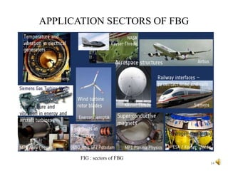


Fiber Bragg gratings are made by periodically changing the refractive index in the core of an optical fiber using ultraviolet light exposure. This creates a filter that reflects a narrow band of wavelengths, while transmitting others. There are different types of gratings including uniform, apodized, and chirped. Fiber Bragg gratings have various applications including use in telecommunications as filters and dispersion compensators. They offer advantages such as flexibility, low loss, and ability to sense parameters that affect the grating pitch or refractive index.


![Alan Lucas - [Template] [Template] [Template] ScienceFairProjectTemplate.pptx](https://cdn.slidesharecdn.com/ss_thumbnails/alanlucas-templatetemplatetemplatesciencefairprojecttemplate-260106222421-b6ad9ab7-thumbnail.jpg?width=640&height=640&fit=bounds)


