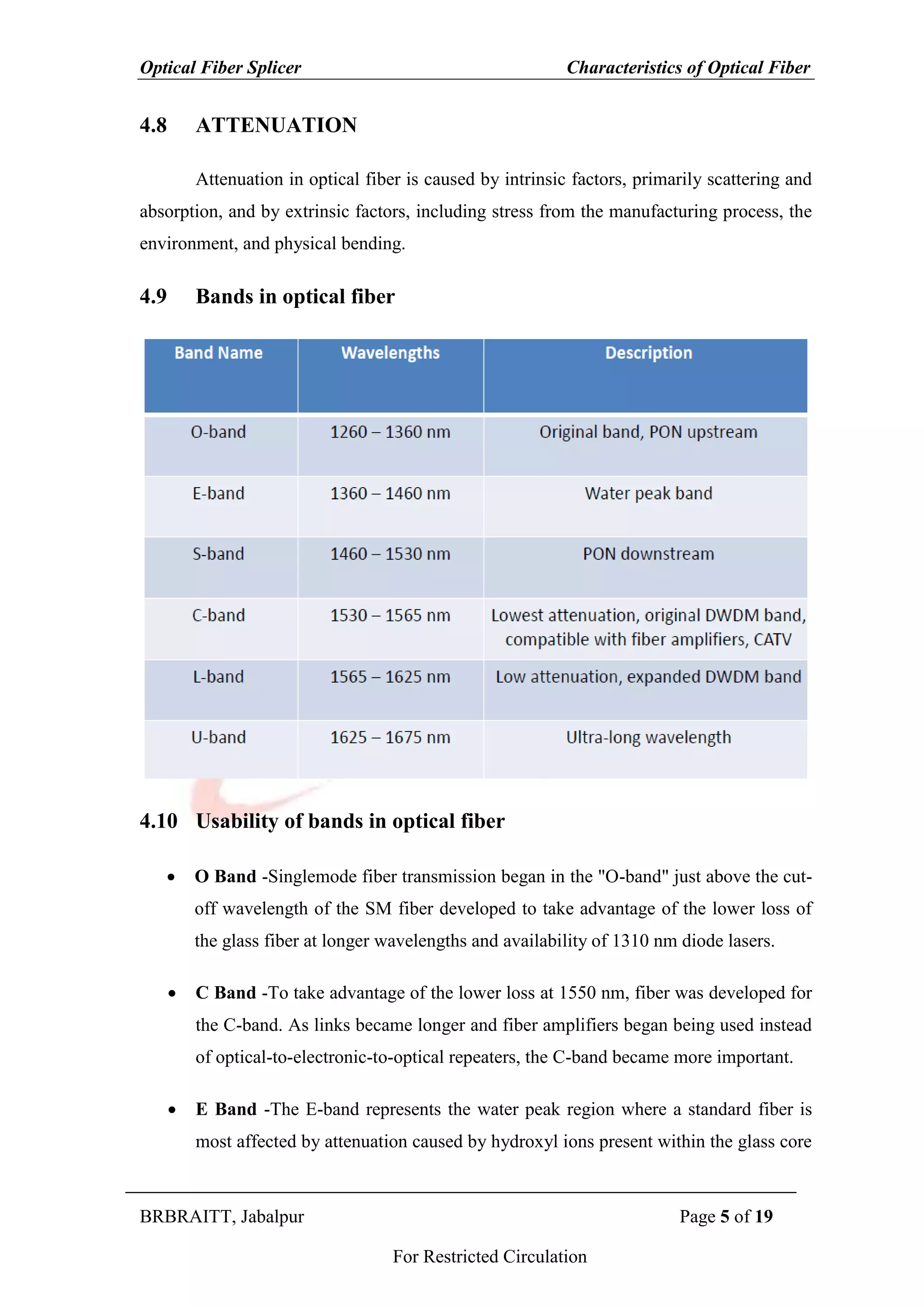
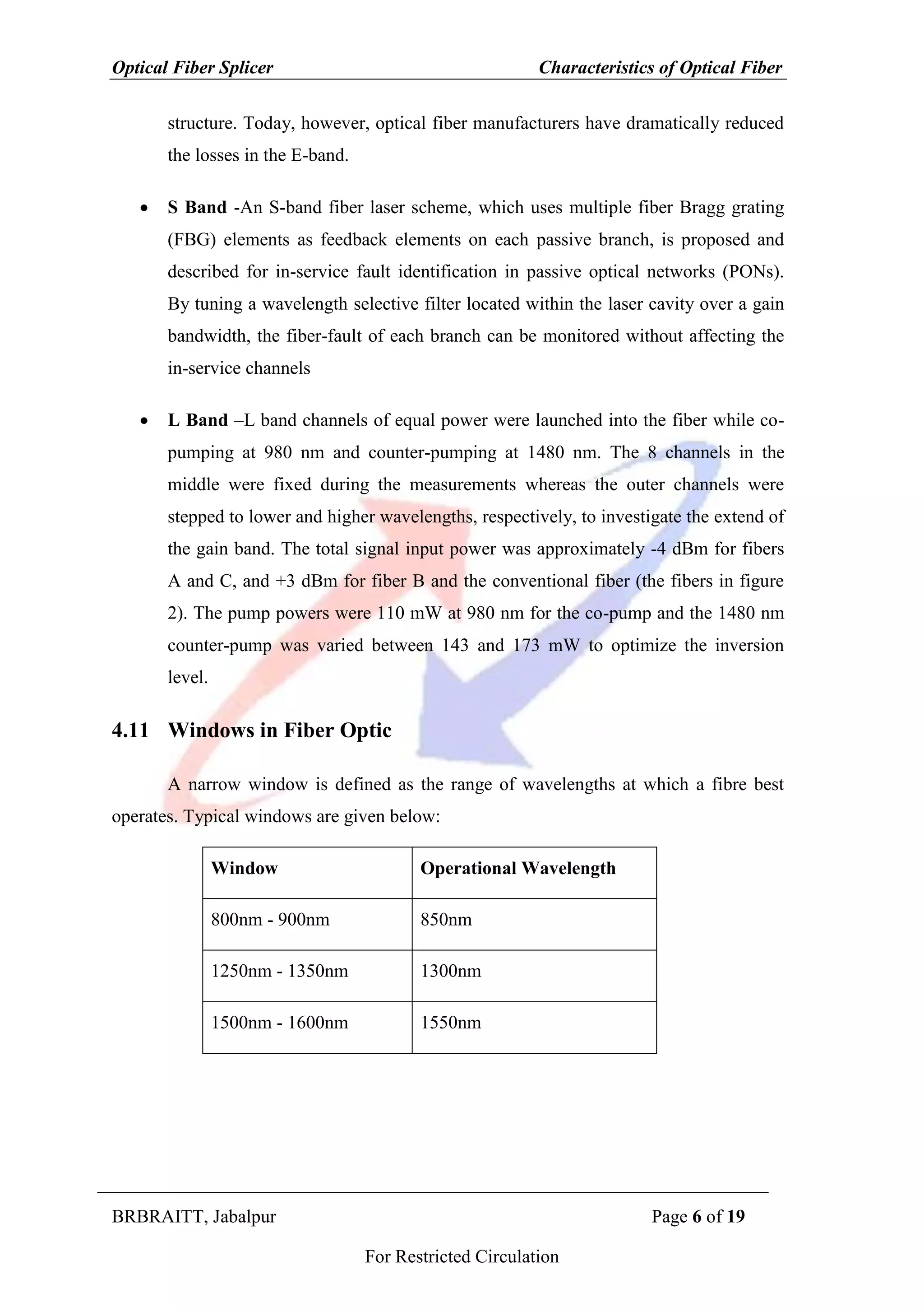
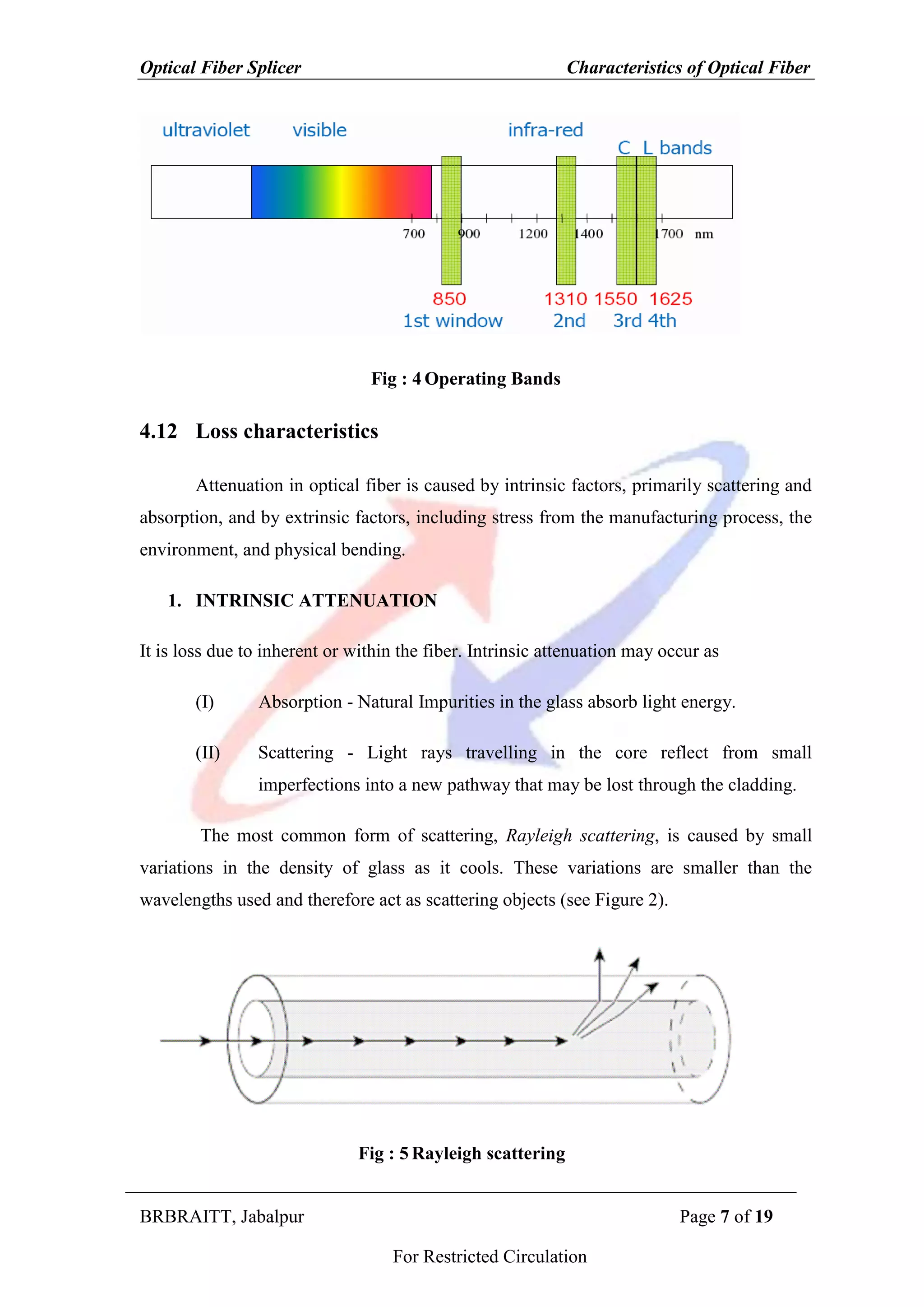
This document discusses key characteristics of optical fibers that affect their performance as a transmission medium. It describes how wavelength, frequency, reflection, refraction, polarization, and attenuation properties influence fiber optic communication. Specific bands used in optical fibers, including O, C, E, S and L bands, are defined. The document also examines intrinsic and extrinsic factors contributing to fiber attenuation, as well as dispersion which limits bandwidth by spreading out light pulses over time as they travel through the fiber.
A brief presentation about optical fiber technology. Presented by Abdessalam BENHARIRA and Laurent PANEK.
Summary
1. What is optical fiber ?
2. How it works ?
3. Different types
4. Uses
5. Advantages and disadvantages
6. Conclusion
An optical fiber is a hair thin cylindrical fiber of glass or any transparent dielectric medium.
The fiber which are used for optical communication are wave guides made of transparent dielectrics.
Its function is to guide visible and infrared light over long distances.
Fiber-optic communication is a method of transmitting information from one place to another by sending pulses of light through an optical fiber. The light forms anelectromagnetic carrier wave that is modulated to carry information.
Optical fiber is used by many telecommunications companies to transmit telephone signals, Internet communication, and cable television signals.
The process of communicating using fiber-optics involves the following basic steps: Creating the optical signal involving the use of a transmitter, relaying the signal along the fiber, ensuring that the signal does not become too distorted or weak, receiving the optical signal, and converting it into an electrical signal.
Optical cable: It serves as transmission medium.
Optical detector: It is responsible for optical to electrical conversion of data and hence responsible for demodulation of the optical carrier. It may be a photodiodes, phototransistor, and photoconductors.
Electrical receiver: It is used for electrical interfacing at the receiver end of the optical link and to perform the signal processing electrically.
Destination: It is the final point at which we receive the information in the form of electrical signal.
Applications -In telecommunication field
In space applications
Broadband applications
Computer applications industrial applications
Mining applications
In medical applications
In military applications etc.
This presentation covers:
Concepts of optical fiber communication in detail
Total internal reflection
inter-modulation, dispersion effects in OFC
Impairments in OFC
Advantages in OFC
Different types of optical cables
OFC network elements : splitters, splices, connectors, lasers
optical sources and optical detectors
Optical Link Budget
This narrated power point presentation attempts to explain the various dispersion mechanisms that are observed in optical fibers. Some fundamental terms and concepts are also discussed. The material will be useful for KTU final year B Tech students who prepare for the subject EC 405, Optical Communications.
The following ppt gives overview about Optical Communication and the underlying principle with the general overview of all the contents for optical communication
Presentation on Optical Fiber for UG Physics students by Dr. P D Shirbhate assistant Professor, Department of Physics G S Gawande college, Umarkhed Dist Yavatmal.
Signal Degradation In Optical Fiber
Losses in an optical fibre:-
The types of losses in a optical fibre are
Attenuation loss
Absorption
Scattering
Bending loss
Dispersion loss
Coupling loss
Bending losses of power in a single mode step index optical fiber due to macro bending has been
investigated for a wavelength of 1550nm. The effects of bending radius (4-15mm, with steps of 1mm), and
wrapping turn (up to 40 turns) on loss have been studied. Twisting the optical fiber and its influence on power
loss also has been investigated. Variations of macro bending loss with these two parameters have been
measured, loss with number of turns and radius of curvature have been measured.
This work founds that the Macro bending and wrapping turn loss increases as the bending radius and wrapping
turn increases.
Analysis on The Impact of Reflectance in Optical Fiber Linksijtsrd
An optical fiber link is a part of an optic fiber communication system. Other components of the optic fiber link include the transmitter, connectors, and the receiver. The optical fiber could be single-mode (for long distance transmission) or multi-mode (for short distance transmission). This paper however, majors on the impact of reflectance in the single-mode optical fiber. Reflectance is a hidden threat that increases Bit Error Rate, BER, (rate at which errors occur in transmission system) and reduces system performance if not monitored or controlled. Optical Time Domain Reflectometer (OTDR) was used to measure the reflectance in single-mode fiber. Events measurements in OTDR heavily depend on good reflectance. The OTDR was able to establish the reflectance in every portion of the fiber under test. An average reflectance level of -14.9275 dB of 1550 nm signal over the span length of 20.422 km was achieved which is within the acceptable standard range. Hence, good quality performance transmissions can be achieved along these routes. J. Ilouno | M. Awoji | J. Sani"Analysis on The Impact of Reflectance in Optical Fiber Links" Published in International Journal of Trend in Scientific Research and Development (ijtsrd), ISSN: 2456-6470, Volume-2 | Issue-4 , June 2018, URL: http://www.ijtsrd.com/papers/ijtsrd14378.pdf http://www.ijtsrd.com/physics/other/14378/analysis-on-the-impact-of-reflectance-in-optical-fiber-links/j-ilouno
Twenty Essential Knowledge of Optical Cable.pdfHYC Co., Ltd
An article about basic knowledge of optical fiber cable, including the wavelength, dispersion of optical fiber, insertion loss, return loss, fiber core diameter, types of optical fiber etc. Including What is the mode field diameter (MFD), What is Numerical Aperture (NA), What is the cutoff wavelength and so on.
About
Indigenized remote control interface card suitable for MAFI system CCR equipment. Compatible for IDM8000 CCR. Backplane mounted serial and TCP/Ethernet communication module for CCR remote access. IDM 8000 CCR remote control on serial and TCP protocol.
• Remote control: Parallel or serial interface.
• Compatible with MAFI CCR system.
• Compatible with IDM8000 CCR.
• Compatible with Backplane mount serial communication.
• Compatible with commercial and Defence aviation CCR system.
• Remote control system for accessing CCR and allied system over serial or TCP.
• Indigenized local Support/presence in India.
• Easy in configuration using DIP switches.
Technical Specifications
Indigenized remote control interface card suitable for MAFI system CCR equipment. Compatible for IDM8000 CCR. Backplane mounted serial and TCP/Ethernet communication module for CCR remote access. IDM 8000 CCR remote control on serial and TCP protocol.
Key Features
Indigenized remote control interface card suitable for MAFI system CCR equipment. Compatible for IDM8000 CCR. Backplane mounted serial and TCP/Ethernet communication module for CCR remote access. IDM 8000 CCR remote control on serial and TCP protocol.
• Remote control: Parallel or serial interface
• Compatible with MAFI CCR system
• Copatiable with IDM8000 CCR
• Compatible with Backplane mount serial communication.
• Compatible with commercial and Defence aviation CCR system.
• Remote control system for accessing CCR and allied system over serial or TCP.
• Indigenized local Support/presence in India.
Application
• Remote control: Parallel or serial interface.
• Compatible with MAFI CCR system.
• Compatible with IDM8000 CCR.
• Compatible with Backplane mount serial communication.
• Compatible with commercial and Defence aviation CCR system.
• Remote control system for accessing CCR and allied system over serial or TCP.
• Indigenized local Support/presence in India.
• Easy in configuration using DIP switches.
Saudi Arabia stands as a titan in the global energy landscape, renowned for its abundant oil and gas resources. It's the largest exporter of petroleum and holds some of the world's most significant reserves. Let's delve into the top 10 oil and gas projects shaping Saudi Arabia's energy future in 2024.
Cosmetic shop management system project report.pdfKamal Acharya
Buying new cosmetic products is difficult. It can even be scary for those who have sensitive skin and are prone to skin trouble. The information needed to alleviate this problem is on the back of each product, but it's thought to interpret those ingredient lists unless you have a background in chemistry.
Instead of buying and hoping for the best, we can use data science to help us predict which products may be good fits for us. It includes various function programs to do the above mentioned tasks.
Data file handling has been effectively used in the program.
The automated cosmetic shop management system should deal with the automation of general workflow and administration process of the shop. The main processes of the system focus on customer's request where the system is able to search the most appropriate products and deliver it to the customers. It should help the employees to quickly identify the list of cosmetic product that have reached the minimum quantity and also keep a track of expired date for each cosmetic product. It should help the employees to find the rack number in which the product is placed.It is also Faster and more efficient way.
Explore the innovative world of trenchless pipe repair with our comprehensive guide, "The Benefits and Techniques of Trenchless Pipe Repair." This document delves into the modern methods of repairing underground pipes without the need for extensive excavation, highlighting the numerous advantages and the latest techniques used in the industry.
Learn about the cost savings, reduced environmental impact, and minimal disruption associated with trenchless technology. Discover detailed explanations of popular techniques such as pipe bursting, cured-in-place pipe (CIPP) lining, and directional drilling. Understand how these methods can be applied to various types of infrastructure, from residential plumbing to large-scale municipal systems.
Ideal for homeowners, contractors, engineers, and anyone interested in modern plumbing solutions, this guide provides valuable insights into why trenchless pipe repair is becoming the preferred choice for pipe rehabilitation. Stay informed about the latest advancements and best practices in the field.
Hybrid optimization of pumped hydro system and solar- Engr. Abdul-Azeez.pdffxintegritypublishin
Advancements in technology unveil a myriad of electrical and electronic breakthroughs geared towards efficiently harnessing limited resources to meet human energy demands. The optimization of hybrid solar PV panels and pumped hydro energy supply systems plays a pivotal role in utilizing natural resources effectively. This initiative not only benefits humanity but also fosters environmental sustainability. The study investigated the design optimization of these hybrid systems, focusing on understanding solar radiation patterns, identifying geographical influences on solar radiation, formulating a mathematical model for system optimization, and determining the optimal configuration of PV panels and pumped hydro storage. Through a comparative analysis approach and eight weeks of data collection, the study addressed key research questions related to solar radiation patterns and optimal system design. The findings highlighted regions with heightened solar radiation levels, showcasing substantial potential for power generation and emphasizing the system's efficiency. Optimizing system design significantly boosted power generation, promoted renewable energy utilization, and enhanced energy storage capacity. The study underscored the benefits of optimizing hybrid solar PV panels and pumped hydro energy supply systems for sustainable energy usage. Optimizing the design of solar PV panels and pumped hydro energy supply systems as examined across diverse climatic conditions in a developing country, not only enhances power generation but also improves the integration of renewable energy sources and boosts energy storage capacities, particularly beneficial for less economically prosperous regions. Additionally, the study provides valuable insights for advancing energy research in economically viable areas. Recommendations included conducting site-specific assessments, utilizing advanced modeling tools, implementing regular maintenance protocols, and enhancing communication among system components.
Final project report on grocery store management system..pdfKamal Acharya
In today’s fast-changing business environment, it’s extremely important to be able to respond to client needs in the most effective and timely manner. If your customers wish to see your business online and have instant access to your products or services.
Online Grocery Store is an e-commerce website, which retails various grocery products. This project allows viewing various products available enables registered users to purchase desired products instantly using Paytm, UPI payment processor (Instant Pay) and also can place order by using Cash on Delivery (Pay Later) option. This project provides an easy access to Administrators and Managers to view orders placed using Pay Later and Instant Pay options.
In order to develop an e-commerce website, a number of Technologies must be studied and understood. These include multi-tiered architecture, server and client-side scripting techniques, implementation technologies, programming language (such as PHP, HTML, CSS, JavaScript) and MySQL relational databases. This is a project with the objective to develop a basic website where a consumer is provided with a shopping cart website and also to know about the technologies used to develop such a website.
This document will discuss each of the underlying technologies to create and implement an e- commerce website.
Governing Equations for Fundamental Aerodynamics_Anderson2010.pdf
Characteristics of optical fiber cable
1. Optical Fiber Splicer Characteristics of Optical Fiber
BRBRAITT, Jabalpur Page 1 of 19
For Restricted Circulation
4 CHARATERISTICS OF OPTICAL FIBER
4.1 INTRODUCTION
4.2 OBJECTIVE
4.3 WAVELENGTH
4.4 FREQUENCY
4.5 REFLECTION
4.6 REFRACTION
4.7 POLARIZATION
4.8 ATTENUATION
4.9 BANDS IN OPTICAL FIBER
4.10 USABILITY OF BANDS IN OPTICAL FIBER
4.11 WINDOWS IN FIBER OPTIC
4.12 LOSS CHARACTERISTICS
4.13 DISPERSION
4.14 BANDWIDTH
4.13 SUMMARY
4.14 REFERENCES AND SUGGESTED FURTHER READINGS
4.15 WORKSHEET
2. Optical Fiber Splicer Characteristics of Optical Fiber
BRBRAITT, Jabalpur Page 2 of 19
For Restricted Circulation
4.1 Introduction
Like any communication system there are some important factors affecting
performance of optical fibers as a transmission medium. The most interest are those
attenuation and bandwidth. Optical-fiber systems have many advantages over metallic-
based communication systems. These advantages include interference, attenuation, and
bandwidth characteristics. Furthermore, the relatively smaller cross section of fiber-optic
cables allows room for substantial growth of the capacity in existing conduits.
4.2 Objective
After reading this unit, you should be able to understand:
Refraction
Polarization
Attenuation
Dispersion
Bandwidth
Optical bands
4.3 WAVELENGTH
It is a characteristic of light that is emitted from the light source and is measures in
nanometers (nm). In the visible spectrum, wavelength can be described as the colour of
the light.
For example, Red Light has longer wavelength than Blue Light, Typical
wavelength for fibre use are 850nm, 1300nm and 1550nm all of which are invisible
(Infrared).
3. Optical Fiber Splicer Characteristics of Optical Fiber
BRBRAITT, Jabalpur Page 3 of 19
For Restricted Circulation
4.4 FREQUENCY
It is number of pulse per second emitted from a light source. Frequency is
measured in units of hertz (Hz). In terms of optical pulse 1Hz = 1 pulse/ sec.
4.5 Reflection
Reflection is the abrupt change in the direction of propagation of a light ray that
strikes the boundary between two different media. At least some part of the incoming
wave remains in the same medium. Assume the incoming light ray makes an angle θi
with the normal of a plane tangent to the boundary. Then the reflected ray makes an
angle θr with this normal and lies in the same plane as the incident ray and the normal.
Fig : 1Reflection of light
Law of reflection: θi = θr
4.6 Refraction
Refraction is the change in direction of propagation of a wave when the light ray
passes from one medium into another, and changes its speed. Light ray are refracted
when crossing the boundary from one transparent medium into another because the speed
of light is different in different media.
When light passes from one transparent medium to another, the rays are bent
toward the surface normal if the speed of light is smaller in the second medium than in
the first. The rays are bent away from this normal if the speed of light in the second
4. Optical Fiber Splicer Characteristics of Optical Fiber
BRBRAITT, Jabalpur Page 4 of 19
For Restricted Circulation
medium is greater than in the first. The picture on the right shows a light wave incident
on a slab of glass.
One part of the wave is reflected, and another part is refracted as it passes into the
glass. The rays are bent towards the normal. At the second interface from glass into air
the light passing into the air is refracted again. The rays are now bent away from the
normal.
Fig : 2 Refraction of light
4.7 Polarization
A light wave that is vibrating in more than one plane is referred to as unpolarized
light. Polarized light waves are light waves in which the vibrations occur in a single
plane. The process of transforming unpolarized light into polarized light is known
as polarization.
Fig : 3 Polarization
5. Optical Fiber Splicer Characteristics of Optical Fiber
BRBRAITT, Jabalpur Page 5 of 19
For Restricted Circulation
4.8 ATTENUATION
Attenuation in optical fiber is caused by intrinsic factors, primarily scattering and
absorption, and by extrinsic factors, including stress from the manufacturing process, the
environment, and physical bending.
4.9 Bands in optical fiber
4.10 Usability of bands in optical fiber
O Band -Singlemode fiber transmission began in the "O-band" just above the cut-
off wavelength of the SM fiber developed to take advantage of the lower loss of
the glass fiber at longer wavelengths and availability of 1310 nm diode lasers.
C Band -To take advantage of the lower loss at 1550 nm, fiber was developed for
the C-band. As links became longer and fiber amplifiers began being used instead
of optical-to-electronic-to-optical repeaters, the C-band became more important.
E Band -The E-band represents the water peak region where a standard fiber is
most affected by attenuation caused by hydroxyl ions present within the glass core
6. Optical Fiber Splicer Characteristics of Optical Fiber
BRBRAITT, Jabalpur Page 6 of 19
For Restricted Circulation
structure. Today, however, optical fiber manufacturers have dramatically reduced
the losses in the E-band.
S Band -An S-band fiber laser scheme, which uses multiple fiber Bragg grating
(FBG) elements as feedback elements on each passive branch, is proposed and
described for in-service fault identification in passive optical networks (PONs).
By tuning a wavelength selective filter located within the laser cavity over a gain
bandwidth, the fiber-fault of each branch can be monitored without affecting the
in-service channels
L Band –L band channels of equal power were launched into the fiber while co-
pumping at 980 nm and counter-pumping at 1480 nm. The 8 channels in the
middle were fixed during the measurements whereas the outer channels were
stepped to lower and higher wavelengths, respectively, to investigate the extend of
the gain band. The total signal input power was approximately -4 dBm for fibers
A and C, and +3 dBm for fiber B and the conventional fiber (the fibers in figure
2). The pump powers were 110 mW at 980 nm for the co-pump and the 1480 nm
counter-pump was varied between 143 and 173 mW to optimize the inversion
level.
4.11 Windows in Fiber Optic
A narrow window is defined as the range of wavelengths at which a fibre best
operates. Typical windows are given below:
Window Operational Wavelength
800nm - 900nm 850nm
1250nm - 1350nm 1300nm
1500nm - 1600nm 1550nm
7. Optical Fiber Splicer Characteristics of Optical Fiber
BRBRAITT, Jabalpur Page 7 of 19
For Restricted Circulation
Fig : 4 Operating Bands
4.12 Loss characteristics
Attenuation in optical fiber is caused by intrinsic factors, primarily scattering and
absorption, and by extrinsic factors, including stress from the manufacturing process, the
environment, and physical bending.
1. INTRINSIC ATTENUATION
It is loss due to inherent or within the fiber. Intrinsic attenuation may occur as
(I) Absorption - Natural Impurities in the glass absorb light energy.
(II) Scattering - Light rays travelling in the core reflect from small
imperfections into a new pathway that may be lost through the cladding.
The most common form of scattering, Rayleigh scattering, is caused by small
variations in the density of glass as it cools. These variations are smaller than the
wavelengths used and therefore act as scattering objects (see Figure 2).
Fig : 5 Rayleigh scattering
8. Optical Fiber Splicer Characteristics of Optical Fiber
BRBRAITT, Jabalpur Page 8 of 19
For Restricted Circulation
Scattering affects short wavelengths more than long wavelengths and limits the
use of wavelengths below 800 nm.
Attenuation due to absorption is caused by the intrinsic properties of the material
itself, the impurities in the glass, and any atomic defects in the glass. These impurities
absorb the optical energy, causing the light to become dimmer. While Rayleigh scattering
is important at shorter wavelengths, intrinsic absorption is an issue at longer wavelengths
and increases dramatically above 1700 nm. However, absorption due to water peaks
introduced in the fiber manufacturing process are being eliminated in some new fiber
types.
Fig : 6 Absorption
The primary factors affecting attenuation in optical fibers are the length of the
fiber and the wavelength of the light. Figure shows the loss in decibels per kilometer
(dB/km) by wavelength from Rayleigh scattering, intrinsic absorption, and total
attenuation.
9. Optical Fiber Splicer Characteristics of Optical Fiber
BRBRAITT, Jabalpur Page 9 of 19
For Restricted Circulation
Fig : 7 Attenuation Vs. Wavelength characteristic
2. EXTRINSIC ATTENUATION
It is loss due to external sources. Extrinsic attenuation may occur as –
(I) Macro bending - The fibre is sharply bent so that the light travelling
down the fibre cannot make the turn & is lost in the cladding.
(II) Micro bending - Microbending or small bends in the fibre caused by
crushing contraction etc. These bends may not be visible with the naked eye.
Attenuation is measured in decibels (dB). A dB represents the comparison between the
transmitted and received power in a system.
Micro bend
Micro bend
Micro bend
Fig : 8 Micro bends
10. Optical Fiber Splicer Characteristics of Optical Fiber
BRBRAITT, Jabalpur Page 10 of 19
For Restricted Circulation
Fig : 9 Macro bend
4.13 DISPERSION
Dispersion is the spreading of light pulse as its travels down the length of
an optical fibre as shown in figure. The varying delay in arrival time between
different components of a signal "smears out" the signal in time. This causes
energy overlapping and limits information capacity of the fiber.
Dispersion limits the bandwidth or information carrying capacity of a
fibre. The bit-rates must be low enough to ensure that pulses are farther apart and
therefore the greater dispersion can be tolerated.
Dispersion of optical energy within an optical fiber falls into following
categories:
Intermodal Delay or Modal Delay
Intramodal Dispersion or Chromatic Dispersion
Material Dispersion
Waveguide Dispersion
11. Optical Fiber Splicer Characteristics of Optical Fiber
BRBRAITT, Jabalpur Page 11 of 19
For Restricted Circulation
Polarization –Mode Dispersion
Fig : 10 Dispersion
1. INTERMODAL DELAY/ MODAL DELAY
Intermodal distortion or modal delay appears only in multimode fibers. This signal
distortion mechanism is a result of each mode having a different value of the group
velocity at a single frequency.
The amount of spreading that occurs in a fiber is a function of the number of
modes propagated by the fiber and length of the fiber
Intermodal or modal dispersion causes the input light pulse to spread. The input
light pulse is made up of a group of modes (MULTIMODE). As the modes
propagate along the fiber, light energy distributed among the modes is delayed by
different amounts. Modes travel in different directions, some modes travel longer
distances.
Modal dispersion occurs because each mode travels a different distance over the
same time span
12. Optical Fiber Splicer Characteristics of Optical Fiber
BRBRAITT, Jabalpur Page 12 of 19
For Restricted Circulation
The modes of a light pulse that enter the fiber at one time exit the fiber different
times.
This condition causes the light pulse to spread.
As the length of the fiber increases, modal dispersion increases.
Fig : 11 Intermodal Dispersion
2. INTRAMODAL DISPESION
Pulse spreading that occurs within a single mode
Intra-modal dispersion occurs because different colors of light travel through
different materials and different waveguide structures at different speeds
Also called GROUP VELOCITY DISPERSION (GVD)
Occurs in all types of fibers
Two main causes : Material dispersion
Waveguide dispersion
A. Material Dispersion
Arises from variations of the refractive index of the core material as a function of
wavelength
Different wavelengths travel at different speeds in the fiber material and hence
exit the fiber at different times
13. Optical Fiber Splicer Characteristics of Optical Fiber
BRBRAITT, Jabalpur Page 13 of 19
For Restricted Circulation
Fig : 12 Material Dispersion
Material dispersion is a function of the source spectral width.
The spectral width specifies the range of wavelengths that can propagate in the
fiber.
Material dispersion is less at longer wavelengths
B. Waveguide Dispersion
Arises because a Single Mode Fiber confines only 80% of the optical power to the
core
The other 20% tends to travel through the cladding and hence travels faster
This results in spreading of the light pulses
The amount of dispersion depends on the fiber design and the size of the fiber
core relative to the wavelength of operation
In multimode fibers, waveguide dispersion and material dispersion are basically
separate properties.
Multimode waveguide dispersion is generally small compared to material
dispersion and is usually neglected.
14. Optical Fiber Splicer Characteristics of Optical Fiber
BRBRAITT, Jabalpur Page 14 of 19
For Restricted Circulation
Arises from dependence of waveguide 'size' on wavelength
Causing light distribution between core and cladding to change with l
Light distribution and dispersion depend on core-cladding design
Proportional to source bandwidth and fiber length
Same dimensions as material dispersion
Can cancel material dispersion if signs are opposite
4.14 BANDWIDTH
It is defined as the amount of information that a system can carry such that each
pulse of light is distinguishable by the receiver. System bandwidth is measured in MHz or
GHz. In general, when we say that a system has bandwidth of 20 MHz, means that 20
million pulses of light per second will travel down the fibre and each will be
distinguishable by the receiver.
1.13.7 BANDWIDTH-LENGTH PRODUCT
Bandwidth is a length dependent. Longer fibre results in more pulse spreading and
leads to lower BW. As a result, the fibre BW is often given in terms of the BW times
kilometer product. A 1000 MHz x km fibre can usually operate with 100 MHz BW if a 10
km fibre is used or with a 1000 MHz BW if a 1 km fibre is used.
1.13.8 ELECTRICAL AND OPTICAL BANDWIDTH
A distinction must be made between electrical and optical BW. Electrical
bandwidth (BWel) is defined drops to 0.707. The optical bandwidth (BWopt) is defined as
the frequency at which the ratio, PLo/PLi dropped to 1/2. (The ratio Iout/Iin and PLo/PLi have
maximum values of 1). Because PLi and PLo are directly proportional to Iin and Iout
respectively (and not to Iin
2
and Iout
2
as in an all electrical system), the half power point is
equivalent to the half current point. That is the point where Iout/Iin drops to 0.50, not to
0.707. This results in a BWopt that is larger than the BWel.
BWel = 0.707 x BWopt
15. Optical Fiber Splicer Characteristics of Optical Fiber
BRBRAITT, Jabalpur Page 15 of 19
For Restricted Circulation
It is important to realize that these two parameters represent two ways of
describing the same system. For example, a system can be said to have an optical BW of
10 MHz, which implies that its electrical BW is 7.07 MHz.
Fig : 13 ELECTRICAL AND OPTICAL BANDWIDTH
4.13 Summary
Fiber-optic characteristics can be classified as linear and nonlinear. Nonlinear
characteristics are influenced by parameters, such as bit rates, channel spacing, and power
levels. The loss or attenuation in fibre depends on the wavelength of the light propagating
within it and Dispersion (sometimes called chromatic dispersion) is a limiting factor in
fibre bandwidth.
4.14 References and Suggested Further Readings
ITU-T manual on OF installation
EI of BSNL
EI on underground OF cable laying works by BBNL
Fiber Optics Technician's Manual
Understanding optical communication by Dutton
Planning Fiber Optic Networks by Bob Chomycz
www.timbercon.com
http://www.ofsoptics.com
16. Optical Fiber Splicer Characteristics of Optical Fiber
BRBRAITT, Jabalpur Page 16 of 19
For Restricted Circulation
http://www.thefoa.org/
http://www.corning.com
http://www.fiber-optics.info
http://www.rp-photonics.com
http://www.occfiber.com and other websites
4.15 Worksheet
Qu.1 Fill in the Blanks
1. Frequency is measured in units of ………
2. ………… is the change in direction of propagation of a wave when the light ray
passes from one medium into another, and changes its speed.
3. ………… due to absorption is caused by the intrinsic properties of the material
itself, the impurities in the glass, and any atomic defects in the glass.
4. …………. is the spreading of light pulse as its travels down the length of an
optical fibre.
5. ……………… dispersion occurs because different colors of light travel through
different materials.
Qu.2 State True or False
1. Dispersion limits the bandwidth or information carrying capacity of a fibre.
2. The primary factors affecting attenuation in optical fibers are the length of the
fiber and the wavelength of the light.
3. Intermodal distortion or modal delay appears only in single mode fibers.
4. Material dispersion is a function of the source spectral width.
5. Bandwidth is a length dependent.
Qu.3 write down the wavelengths of optical windows?
1.
2.
3.