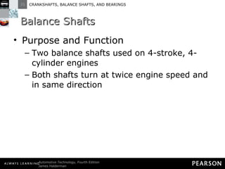
This document discusses crankshafts, balance shafts, and engine bearings. It describes the purpose and function of crankshafts, how they are constructed and balanced using counterweights. It also discusses the different types of crankshaft designs used in various engine configurations like V6, V8, inline 4 and 6 cylinder engines. Balance shafts are introduced as a way to reduce engine vibration.
Design and Analysis of Crankshaft for Internal Combustion Engineijtsrd
In this project design and analysis of the crankshaft for the combustion engine. These components have a large volume component with complex geometry and need huge investment. These will be converts reciprocating or linear motion of the piston into a rotary motion. In this project the product is modeled in a 3D model with all available constraint by using advanced cad software CATIA V5. this model will be converted to initial graphics exchange specification IGES format and imported to ANSYS workbench to perform static analysis. Finite element analysis FEA is performed to obtain the various stress and critical location of crankshaft under loads by using ANSYS software. This project helps to many researchers to select best material to production of crankshaft. Md. Hameed | Chova Deekshith | Gorge Bhanu Prasad | Chalamala Teja ""Design and Analysis of Crankshaft for Internal Combustion Engine"" Published in International Journal of Trend in Scientific Research and Development (ijtsrd), ISSN: 2456-6470, Volume-3 | Issue-3 , April 2019, URL: https://www.ijtsrd.com/papers/ijtsrd23531.pdf
Paper URL: https://www.ijtsrd.com/engineering/mechanical-engineering/23531/design-and-analysis-of-crankshaft-for-internal-combustion-engine/md-hameed
bevel gear screw jack,high speed screw jack,quick lifting screw jack,gear ratio 1:1 screw jack features:
1. Load capacity 25kN to 500kN. When full load, worm torque high speed 92Nm to 4712Nm, low speed 46Nm to 2828Nm.
2. Lift screw diameter 30 mm to 120 mm, screw pitch 6 mm to 16 mm.
3. High gear ratio 1:1, low gear ratio 2:1.
4. Translating screw, rotating screw, keyed screw configurations in upright or inverted mounting orientation.
5. Difference from worm gear screw jack, driven spindle by spiral bevel gear sets.
5. Manual operated bevel gear screw jack by hand wheel or hand crank, or electrically operated bevel gear screw jack by 3-phase or single phase motor or gear motor.
6. Processing lift screw stroke according to clients needs. Under max. compression load, without guides 250mm to 1000mm stroke, with guides 400mm to 2000mm stroke. Under tension load, max. 1500mm to 5500mm stroke.
7. Lift screw end fittings include top plate, clevis end, plain end and threaded end.
8. Full synchronization bevel gear screw jack system, doesn't require right angle bevel gearbox to transmit torque and power, bevel gear screw jacks are directly connected by line shaftings and couplings.
9. Application in steel, pipe, tube, plate, roll forming roller adjustment, feeder straightener rolls adjustment, adjusting synchronous coil feed lines rolls, precision roller leveler, coil sheet slitter line, paint coating line, cut to length line, tension levelling line, continuous galvanizing line, beverage production line, foam concrete cutting machine, sanding machine, heavy vehicles mobile lifting platform, bottle monitoring system height adjustment, conveyor adjustment, plate saw angle adjustment, spray infeed conveyor lift system, theatre stage lifting platform, solar tracker, satellite dish antenna azimuth, raising sluice gate, screw scissor lift table, synchronized lifting system, food processing lifting system, extrusion machine, cnc steel leveling machine, blow molding machine, curing oven lifts, bolted tank, steel shuttering concrete beams adjustment, vintage industrial crank desk, solar panel tracking system, railway maintenance lifting jack, damper adjustment, continuous casting, cnc cut to length machine, robotics arm raising, palletizer, extrusion machine, motorized self-raising tower system, angle tilt adjustments with double clevis, aircraft docking system, open and close flood gates, metallurgy industry, mining industry, chemical industry, construction industry and irrigation industry.
William Good: Extra Small Modular ReactorsEnergyTech2015
EnergyTech2015.com
TERRESTRIAL POWER TECHNOLOGY II
Track 2 Session 2
Moderator: Don Brown, NASA
This session continued the previous session’s exploration of technologies to improve terrestrial power systems including; power systems for building and industrial power, advanced generation, energy storage and smart grid developments.
David J. Sadey: Paper 1: Operation and Control of a Three-Phase Megawatt-Class Variable Frequency Power Generation and Distribution System
William Good: Paper 2: Modular Nuclear Power
Josh Sparber: Paper 3: Effective Measures for Protection of US Power Grid
Neil Tyrrell : Paper 4: Fast and flexible combined cycle gas turbines
Branndon Kelley Keynote on Cybersecurity and the Smart Utility EnergyTech2015
In an effort to make a Utility more “Smart” the business units within are requiring additional data for business intelligence, predictive and data analytics and asset optimization. To acquire the necessary data points the once “disconnected” power plants, electric grid, and the consumer now have to be connected. Utilizing sensor technology, advanced metering, and automated controls the systems within the power plant, transmission & distribution grid, and even a home or business now become vulnerable. In addition to this business-enabling concept the threat of a full-fledged cyber-attack or at the minimum cyber espionage is real. Utilities are now faced with these threats and must spend enormous amounts of capital and operational dollars to protect their assets utilizing a “not if, but when” mentality. The two competing concepts create a paradox – the more we connect the utility, the more vulnerable it be- comes -however, without connecting the utility, the less “Smart” we can be.
Tues.1040 am states role in protecting electric grids from emp and gmd with a...EnergyTech2015
EnergyTech2015.com Track 4 Session 2 SHAPING POLICY ON CRITICAL INFRASTRUCTURE PROTECTION AND RECOVERY Moderator: Mike DeLamare Panelists will briefly present current policy efforts, or the effects of policy on providers. This will be followed by Q&A from the audience. Panelists: Andrea Boland: Discuss current and pending Legislation for the State of Maine as compared to other States: /Maine John Ostrich: Speaking on the Space Weather Policy and Action Plan Patrick Shaw: Addressing the business continuity and the emergency management consequences of long-term power outages Kevin Goodman: Policy effects on Power and Data Centers Chuck Manto: Policy as a catalyst for technical innovations
Benjamin Loop: Simulation Environment for Power Management and Distribution D...EnergyTech2015
EnergyTech2015.com
SPACE POWER SYSTEMS
Track 2 Session 4 Moderator: James Soeder
This session explored power technologies being developed to enable more advanced deep space missions including; unique power systems, autonomous and intelligent control and real time simulation
Ms Anne McNellis: Paper 1: NASA Intelligent Power Control,
Dr Benjamin Loop: Paper 2: Real Time Simulation for NASA Intelligent Power Control Development
Dr Brad Glenn: Paper 3: Helm Algorithm Development for NASA Intelligent Power Control
Andrew Ritch: Interruption in the Utility IndustryEnergyTech2015
EnergyTech2015.com
INTERRUPTION IN THE UTILITY INDUSTRY?
Track 1 Session 1
Electricity markets are experiencing fundamental changes because of solar, wind, electric vehicles, energy efficiency programs, storage and other forms of distributed generation that may be intermittent or require changes/upgrades to the electric grid. There is also an increase in the availability of smart meters and other devices that can help customers control their electric demand and usage. As a result, demand is less predictable and more volatile. This change also creates challenges for transmission and distribution for all load serving entities, even with new real-time data availability and grid visibility. What technological, regulatory, and/or policy changes are needed in the short term and longer term to keep pace? What will these changes mean for reliability? How will the traditional utility model change in the coming years?
Moderator: Commissioner Beth Trombold, PUCO
Robert Wargo, Vice President, Reliability First Corp.
Andrew Ritch, Energy Wholesale Renewables Director, Duke Energy
Andrew Ott, Executive Vice President, PJM Interconnection
Gareth Digby: Systems-Based Approach to Cyber Investigations EnergyTech2015
EnergyTech2015.com
ENERGIZING MBSE IN ORGANIZATIONS
Track 3 Session 4 Moderator: Matthew Hause
Implementing System Engineering disciplines and practices in an energy company and a panel discussion of how to promote the use of MBSE in the energy systems.
Gareth Digby: A Systems-based Approach To Cyber Investigations The presentation discusses the role of a systems-based approach to cyber investigations and demonstrates how such an approach can help the investigator ensure that a holistic view is take to the identification and analysis of appropriate evidence. Systems engineers are familiar with the need to consider the system within its environment while being aware of the interaction of the system with both people and other systems. These aspects also need to be considered when we investigate what has happened to a system as well as when we create systems.
One element of this systems-based approach is the Human-System-Environment matrix, which offers an appropriate framework to guide the collection of evidence. In particular the matrix emphasizes the temporal aspects associated with evidence gathering. In addition the cyber investigator is not dealing with a system in isolation. The systems-based approach discusses the need to identify the interfaces of the system with the greater system-of-systems.
The value of this systems-based approach to the various stages of a cyber investigation is described, including during the incident investigation, the collection of evidence and the analysis of data. This systems-based approach for an investigation gives the investigator the freedom to go in appropriate directions as the investigation proceeds while ensuring the investigator covers the breadth needed
Anurandha Annaswamy: Computation Model of the Nexus Between Natural Gas and E...EnergyTech2015
THE GAS AND ELECTRIC UTILITY INDUSTRY: CARBON CONSTRAINED
Monday, November 30th Track 1 Session 3
This session will focus on the impact U.S. EPA Clean Power Plan (CPP) will play in shaping changes to the natural gas market, including the shale gas marketplace both domestically and perhaps internationally. The inter-dependency between the natural gas and electric industry is growing as there is more movement toward natural gas fired generation and away from coal fired generation. Natural gas companies are already seeing an increased need for infrastructure expansion from the growing gas-electric inter-dependency. What are the benefits and risks facing the natural gas industry? What role does the shale gas industry play? What will the changes mean for gas producers, electric utilities and technology now and in the future both in the U.S and abroad?
Track One Changing Dynamics of the Global Energy Landscape: What are the major forces driving the sea-changes occurring in all phases of Energy Systems i.e., Exploration, Generation, Distribution, Consumption, etc; Systems Support to Policy & Decision Makers; Energy Economics and Politics; how will Systems Engineering facilitate decision making?
Anurandha Annaswamy from Massachusetts Institute of Technology
Jenita McGowan is responsible as Chief of Sustainability for advising the City on policies related to sustainability and the oversight of the Office of Sustainability; leading the coordination of Sustainable Cleveland 2019 to develop new strategies that allow Cleveland to use sustainability as an innovation engine for economic growth, and reducing the City’s ecological footprint with solutions that also save the City money.
SPACE POWER SYSTEMS
Track 2 Session 4 Moderator: James Soeder
This session explored power technologies being developed to enable more advanced deep space missions including; unique power systems, autonomous and intelligent control and real time simulation
Ms Anne McNellis: Paper 1: NASA Intelligent Power Control,
Dr Benjamin Loop: Paper 2: Real Time Simulation for NASA Intelligent Power Control Development,
Dr Brad Glenn: Paper 3: Helm Algorithm Development for NASA Intelligent Power Control,
EnergyTech2015.com Track 4 Session 2 SHAPING POLICY ON CRITICAL INFRASTRUCTURE PROTECTION AND RECOVERY Moderator: Mike DeLamare Panelists will briefly present current policy efforts, or the effects of policy on providers. This will be followed by Q&A from the audience. Panelists: Andrea Boland: Discuss current and pending Legislation for the State of Maine as compared to other States: /Maine John Ostrich: Speaking on the Space Weather Policy and Action Plan Patrick Shaw: Addressing the business continuity and the emergency management consequences of long-term power outages Kevin Goodman: Policy effects on Power and Data Centers Chuck Manto: Policy as a catalyst for technical innovations
Josh Long: Minimum Cyber Security Requirements for a 20 MW Photo Voltaic Field EnergyTech2015
EnergyTech2015.com Track 4 Session 3 RESILIENT APPLICATIONS Moderator: Mike Delamare
Josh Long: Minimum Cyber Security Requirements for a 20 MW Photo Voltaic Field
Brian Patterson: The role of Direct Current micro-grids and data centers for efficiency and resilience
Irv Badr: Managing Risk Factors in Critical Infrastructure
David Sadey, Operation and Control of a Three-Phase Megawatt Class Variable F...EnergyTech2015
EnergyTech2015.com
TERRESTRIAL POWER TECHNOLOGY II
Track 2 Session 2
Moderator: Don Brown, NASA
This session will continue the previous session’s exploration of technologies to improve terrestrial power systems including; power systems for building and industrial power, advanced generation, energy storage and smart grid developments.
David J. Sadey: Paper 1: Operation and Control of a Three-Phase Megawatt-Class Variable Frequency Power Generation and Distribution System
William Good: Paper 2: Modular Nuclear Power
Josh Sparber: Paper 3: Effective Measures for Protection of US Power Grid
Neil Tyrrell : Paper 4: Fast and flexible combined cycle gas turbines
Irv Badr: Managing Risk Safety and Security Compliance EnergyTech2015
EnergyTech2015.com
Track 4 Session 3
RESILIENT APPLICATIONS
Moderator: Mike Delamare
Josh Long: Paper 1 - Minimum Cyber Security Requirements for a 20 MW Photo Voltaic Field
Brian Patterson: Paper 2 - The role of Direct Current micro-grids and data centers for efficiency and resilience
Irv Badr: Paper 3 - Managing Risk Factors in Critical Infrastructure
After many years of research Volkswagen Group created the first successful automotive W engine, with the introduction of its W8 engine (as a test bed for W12). The W12 combines two narrow-angle VR6 engines around a single crankshaft for a total of four banks of cylinders. For this reason, the four-bank configuration is sometimes, and more accurately, referred to as a "VV" or "VR", to distinguish it from the traditional three-bank "W" design. Volkswagen Group went on to produce a W16 engine prototype which produced 465 kilowatts (624 bhp).
A quad-turbocharged version of this engine went into production in 2005 powering the 736 kilowatts (987 bhp). The major advantage of these engines is packaging; that is, they contain high numbers of cylinders but are relatively compact in their external dimensions. In 2006, the Volkswagen Group-owned Bugatti produced an impossible missile, the Bugatti Veyron EB16.4, a supercar; with an 8.0 litre W16 engine. This had four turbochargers, and it produces motive power output of 736 kilowatts (987 bhp) at 6,000rpm. It utilises four valves per cylinder, 64 valves total, with four overhead camshafts. This car is now the fastest production car of world with unbelievable speed of 432kph and may be it goes on in coming years.
A brief explanation of both two stroke engine and four stroke engine with appropriate figures. It can also submitted to professor at the time of submission.
14. Figure 35-1 Typical crankshaft with main journals that are supported by main bearings in the block. Rod journals are offset from the crankshaft centerline.
15.
16. Figure 35-2 The crankshaft rotates on main bearings. Longitudinal (end-to-end) movement is controlled by the thrust bearing.
17.
18.
19.
20. Figure 35-3 A ground surface on one of the crankshaft cheeks next to a main bearing supports thrust loads on the crank.
21.
22.
23.
24. Figure 35-4 The distance from the crankpin centerline to the centerline of the crankshaft determines the stroke, which is the leverage available to turn the crankshaft.
32. Figure 35-5 Wide separation lines of a forged crankshaft.
33.
34.
35.
36.
37.
38. Figure 35-6 Cast crankshaft showing the bearing journal overlap and a straight, narrow cast mold parting line. The amount of overlap determines the strength of the crankshaft.
39.
40.
41. Figure 35-7 A billet crankshaft showing how it is machined from a large round roll of steel, usually 4340 steel, at the right and the finished crankshaft on the left.
69. Figure 35-12 A fully counterweighted 4-cylinder crankshaft.
70.
71.
72. Figure 35-13 The crank throw is halfway down on the power stroke. The piston on the left without an offset crankshaft has a sharper angle than the engine on the right with an offset crankshaft.
73.
74.
75.
76. Figure 35-14 A crankshaft broken as a result of using the wrong torsional vibration damper.
77.
78.
79.
80.
81. Figure 35-15 The hub of the harmonic balancer is attached to the front of the crankshaft. The elastomer (rubber) between the inertia ring and the center hub allows the absorption of crankshaft firing impulses.
90. Figure 35-17 In a 4-cylinder engine, the two outside pistons move upward at the same time as the inner pistons move downward, which reduces primary unbalance.
91.
92. Figure 35-18 Primary and secondary vibrations in relation to piston position.
97. Figure 35-19 Two counterrotating balance shafts used to counterbalance the vibrations of a 4-cylinder engine
98.
99. Figure 35-20 This General Motors 4-cylinder engine uses two balance shafts driven by a chain at the rear of the crankshaft.
100.
101. Figure 35-21 Many 90-degree V-6 engines use a balance shaft to reduce vibrations and effectively cancel a rocking motion (rocking couple) that causes the engine to rock front to back.
108. Figure 35-22 Scored connecting rod bearing journal.
109.
110.
111.
112. Figure 35-23 All crankshaft journals should be measured for diameter as well as taper and out-of-round.
113. Figure 35-24 Check each journal for taper and out-of-round.
114.
115.
116.
117.
118.
119.
120.
121. Figure 35-25 The rounded fillet area of the crankshaft is formed by the corners of the grinding stone.
122.
123. Figure 35-26 An excessively worn crankshaft can be restored to useful service by welding the journals, and then machining them back to the original size.
124.
125. Figure 35-27 All crankshafts should be polished after grinding. Both the crankshaft and the polishing cloth are being revolved.
132. Figure 35-29 The two halves of a plain bearing meet at the parting faces.
133.
134. Figure 35-30 Bearing wall thickness is not the same from the center to the parting line. This is called eccentricity and is used to help create an oil wedge between the journal and the bearing.
135.
136.
137.
138.
139.
140.
141.
142.
143.
144.
145. Figure 35-31 Typical two- and three-layer engine bearing inserts showing the relative thickness of the various materials.
146.
147.
148.
149. Figure 35-32 Typical bearing shell types found in modern engines: (a) half-shell thrust bearing, (b) upper main bearing insert, (c) lower main bearing insert, (d) full round-type camshaft bearing.
150.
151. Figure 35-33 Bearings are often marked with an undersize dimension. This bearing is used on a crankshaft with a ground journal that is 0.020 in. smaller in diameter than the stock size.
152.
153.
154.
155.
156.
157.
158.
159.
160.
161. Figure 35-34 Work hardened bearing material becomes brittle and cracks, leading to bearing failure.
162.
163.
164.
165.
166. Figure 35-35 Bearing material covers foreign material (such as dirt) as it embeds into the bearing.
196. Figure 35-41 Cam-in-block engines support the camshaft with sleeve-type bearings.
197.
198.
199. Figure 35-42 Camshaft bearings must be installed correctly so that oil passages are not blocked.
200.
201.
202.
203.
204.
205.
206. Figure 35-43 Some overhead camshaft engines use split bearing inserts.
207.
208.
209.
210.
211.
Editor's Notes
Figure 35-1 Typical crankshaft with main journals that are supported by main bearings in the block. Rod journals are offset from the crankshaft centerline.
Figure 35-2 The crankshaft rotates on main bearings. Longitudinal (end-to-end) movement is controlled by the thrust bearing.
Figure 35-3 A ground surface on one of the crankshaft cheeks next to a main bearing supports thrust loads on the crank.
Figure 35-4 The distance from the crankpin centerline to the centerline of the crankshaft determines the stroke, which is the leverage available to turn the crankshaft.
Figure 35-5 Wide separation lines of a forged crankshaft.
Figure 35-6 Cast crankshaft showing the bearing journal overlap and a straight, narrow cast mold parting line. The amount of overlap determines the strength of the crankshaft.
Figure 35-7 A billet crankshaft showing how it is machined from a large round roll of steel, usually 4340 steel, at the right and the finished crankshaft on the left.
Figure 35-8 Crankshaft sawed in half, showing drilled oil passages between the main and rod bearing journals.
Figure 35-9 Typical chamfered hole in a crankshaft bearing journal.
Figure 35-10 A cross-drilled crankshaft is used on some production engines and is a common racing modification.
Figure 35-11 A splayed crankshaft design is used to create an even-firing 90-degree V-6.
Figure 35-12 A fully counterweighted 4-cylinder crankshaft.
Figure 35-13 The crank throw is halfway down on the power stroke. The piston on the left without an offset crankshaft has a sharper angle than the engine on the right with an offset crankshaft.
Figure 35-14 A crankshaft broken as a result of using the wrong torsional vibration damper.
Figure 35-15 The hub of the harmonic balancer is attached to the front of the crankshaft. The elastomer (rubber) between the inertia ring and the center hub allows the absorption of crankshaft firing impulses.
Figure 35-16 A General Motors high-performance balancer used on a race engine.
Figure 35-17 In a 4-cylinder engine, the two outside pistons move upward at the same time as the inner pistons move downward, which reduces primary unbalance.
Figure 35-18 Primary and secondary vibrations in relation to piston position.
Figure 35-19 Two counterrotating balance shafts used to counterbalance the vibrations of a 4-cylinder engine
Figure 35-20 This General Motors 4-cylinder engine uses two balance shafts driven by a chain at the rear of the crankshaft.
Figure 35-21 Many 90-degree V-6 engines use a balance shaft to reduce vibrations and effectively cancel a rocking motion (rocking couple) that causes the engine to rock front to back.
Figure 35-22 Scored connecting rod bearing journal.
Figure 35-23 All crankshaft journals should be measured for diameter as well as taper and out-of-round.
Figure 35-24 Check each journal for taper and out-of-round.
Figure 35-25 The rounded fillet area of the crankshaft is formed by the corners of the grinding stone.
Figure 35-26 An excessively worn crankshaft can be restored to useful service by welding the journals, and then machining them back to the original size.
Figure 35-27 All crankshafts should be polished after grinding. Both the crankshaft and the polishing cloth are being revolved.
Figure 35-29 The two halves of a plain bearing meet at the parting faces.
Figure 35-30 Bearing wall thickness is not the same from the center to the parting line. This is called eccentricity and is used to help create an oil wedge between the journal and the bearing.
Figure 35-31 Typical two- and three-layer engine bearing inserts showing the relative thickness of the various materials.
Figure 35-32 Typical bearing shell types found in modern engines: (a) half-shell thrust bearing, (b) upper main bearing insert, (c) lower main bearing insert, (d) full round-type camshaft bearing.
Figure 35-33 Bearings are often marked with an undersize dimension. This bearing is used on a crankshaft with a ground journal that is 0.020 in. smaller in diameter than the stock size.
Figure 35-34 Work hardened bearing material becomes brittle and cracks, leading to bearing failure.
Figure 35-35 Bearing material covers foreign material (such as dirt) as it embeds into the bearing.
Figure 35-36 Bearing spread and crush.
Figure 35-37 Bearings are thinner at the parting line faces to provide crush relief.
Figure 35-38 Spun bearing. The lower cap bearing has rotated under the upper rod bearing.
Figure 35-39 The tang and slot help index the bearing in the bore.
Figure 35-40 Many bearings are manufactured with a groove down the middle to improve the oil flow around the main journal.
Figure 35-41 Cam-in-block engines support the camshaft with sleeve-type bearings.
Figure 35-42 Camshaft bearings must be installed correctly so that oil passages are not blocked.
Figure 35-43 Some overhead camshaft engines use split bearing inserts.