Downloaded 587 times


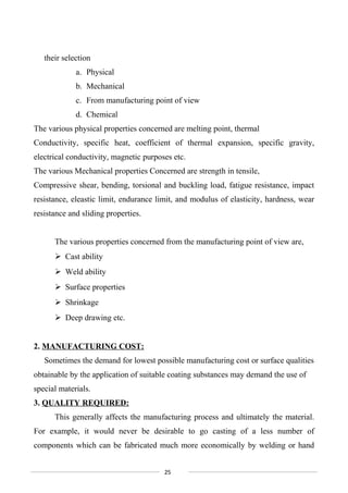
![4.1 DESIGN CALCULATIONS
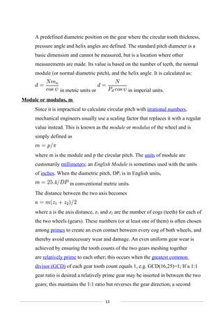
Using Buckingham’s and Lewis Equations:
1) Selection of Material:
Gears, pinion and shafts are made of mild steel.
2) Calculation of Transmissibility Ratio:
I = (Z2/Z1) = (30/20) = 1.5
3) Calculation of tangential load:
Ft = (K0*103
*W) / Vm
K0 = 1.5 (for median life)
= (1.5*750)/Vm
Vm = (Пd1N1)/60 = (ПmZ1N1)/ (60*1000)
= (П*m*20*300)/ (60*1000)
Vm = 0.314m
Which implies,
Ft = (1.5*750)/Vm
= (3582.8)/m
4) Calculation of initial dynamic load:
Fd = Ft * Cv
Cv = (6 + Vm)/ 6 = 3 (Assume Vm = 12)
Fd = (3*3582.8)/m = 10748.4/m
5) Calculation of Beam Strength:
b= 10m
FB= [σb] by*Pa = 720*10*m*y*П*m
Y=0.1084
FB = 2450.70 m2
6) Calculation of module:
2450.70m2
= (10748.4)/m
18](https://image.slidesharecdn.com/twospeedvtgbfinal-160408141220/85/Two-speed-gear-box-mini-project-18-320.jpg)


The document describes a project report for the design and fabrication of a two speed variable transmission gearbox. It was submitted by two students, G. Aravind and S. Arun Muzhithevan, in partial fulfillment of their Bachelor of Engineering degree in Mechanical Engineering at St. Joseph's College of Engineering. The report provides an acknowledgment of those who assisted and supervised the project, a table of contents, descriptions of gearboxes and gear types such as spur gears, and explanations of concepts such as pitch circles and lines of action.