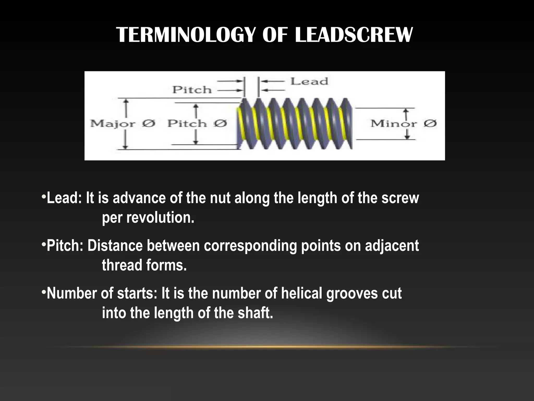
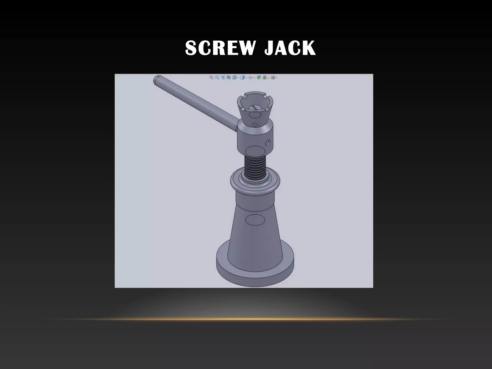
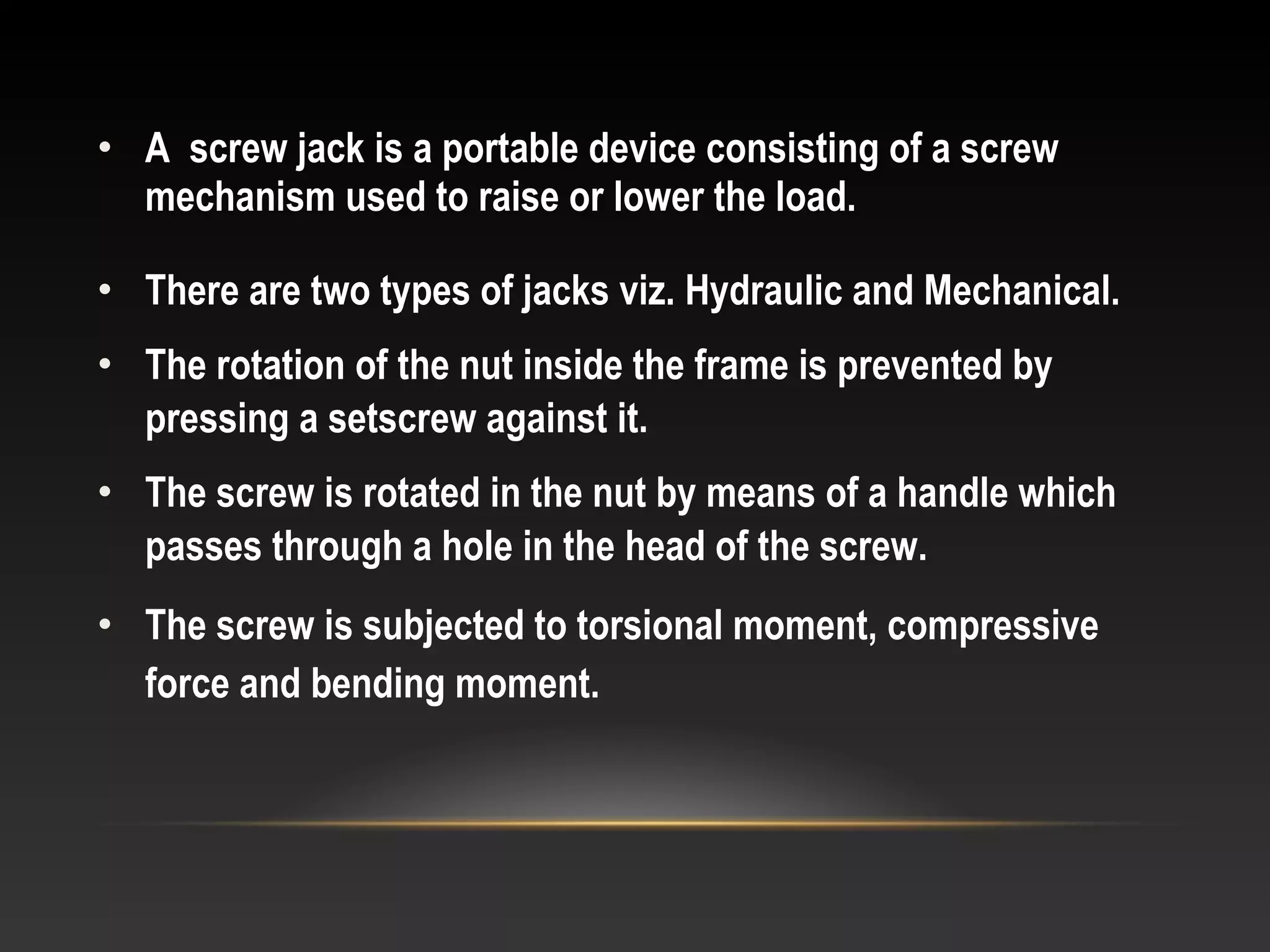
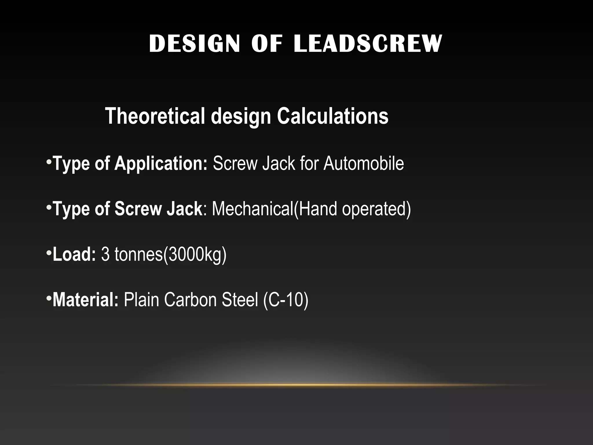
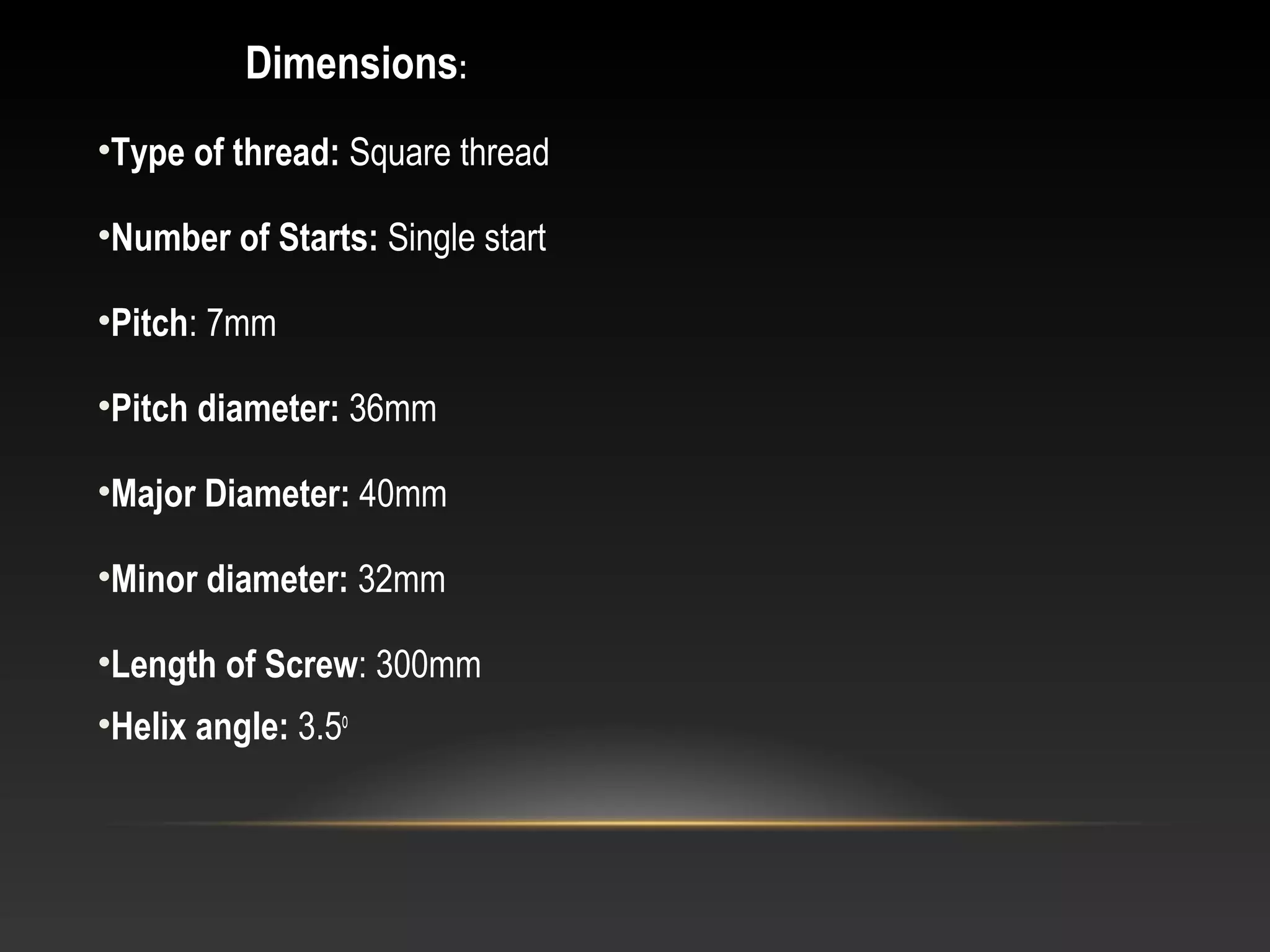
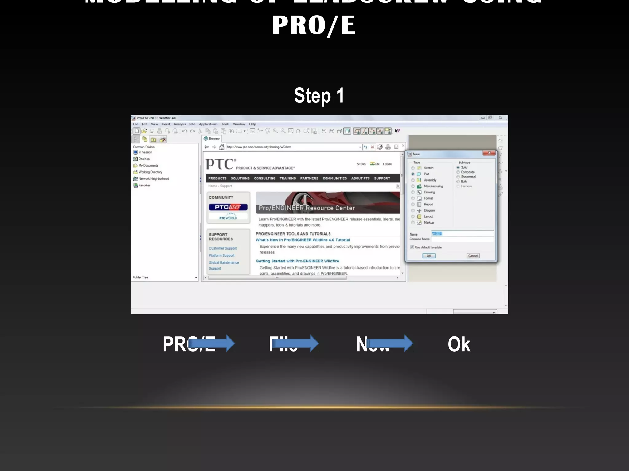
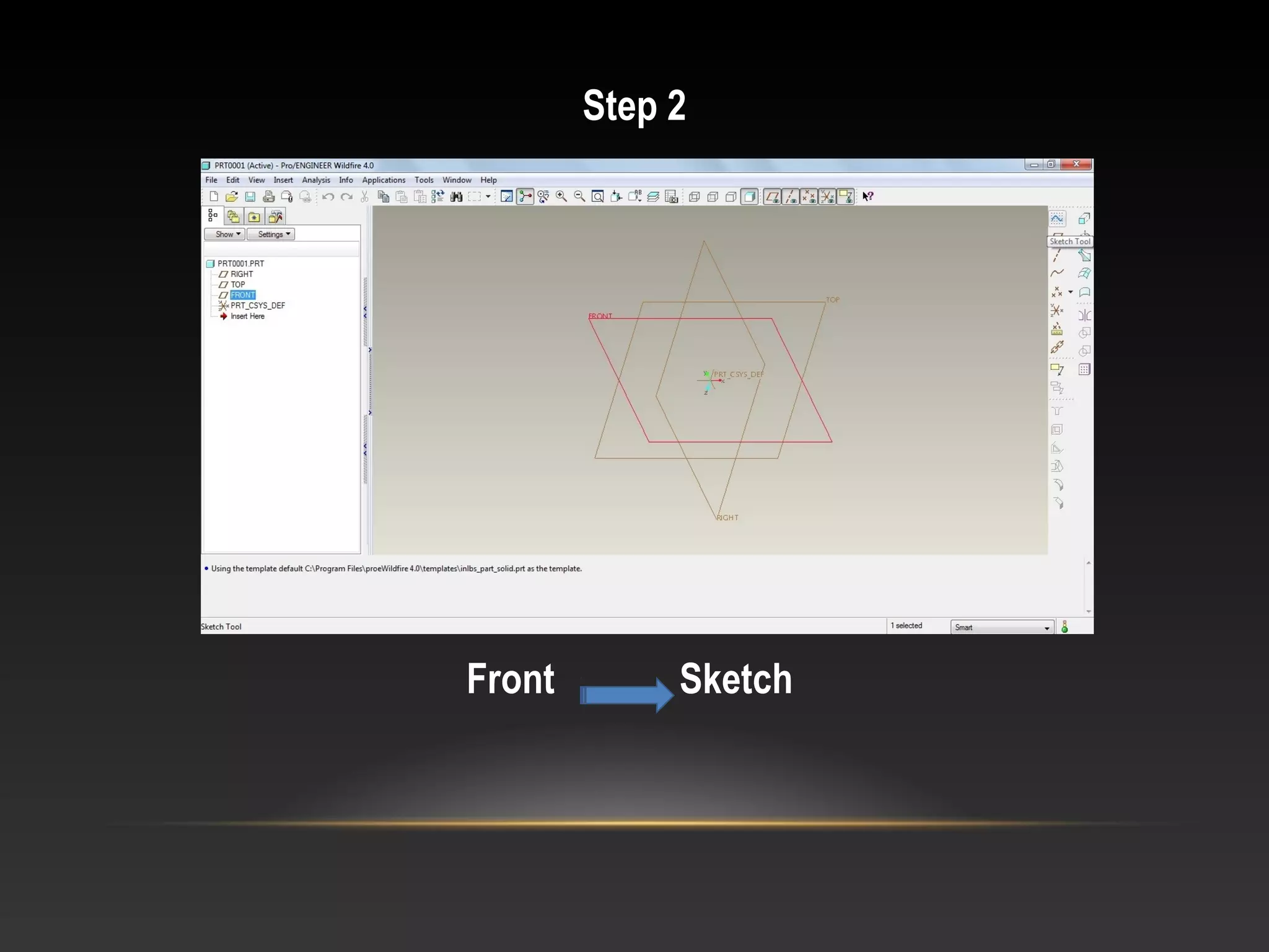
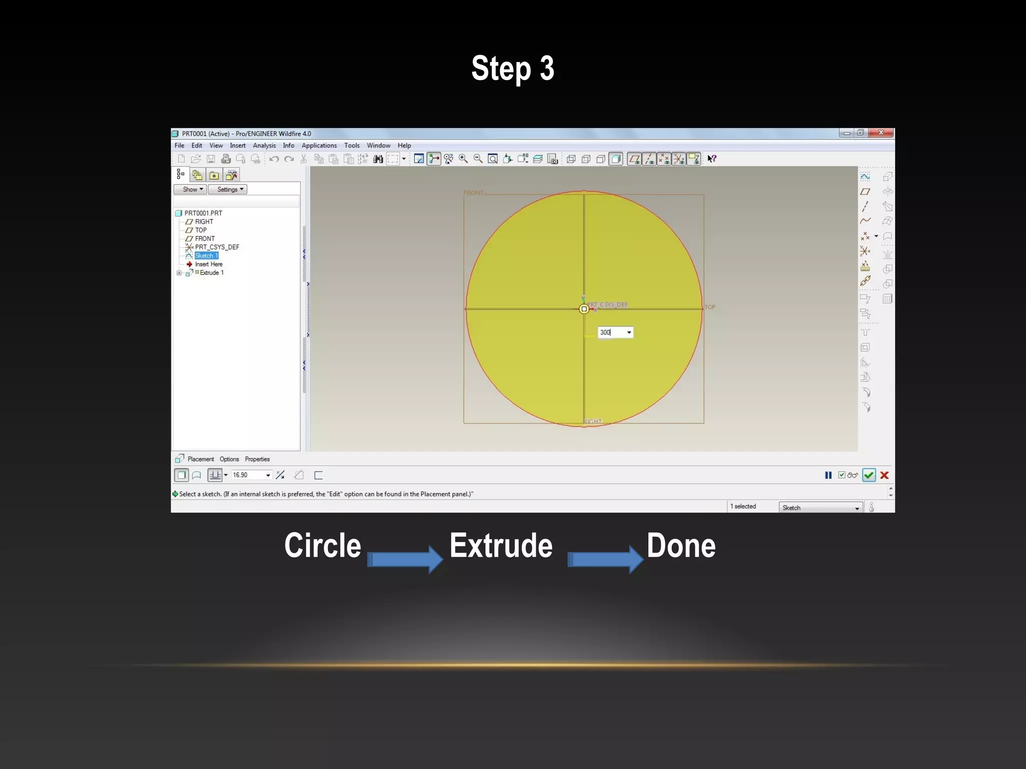
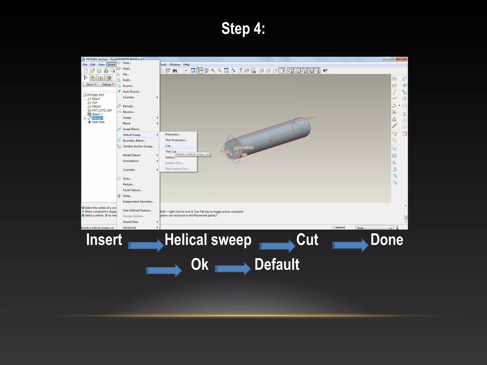
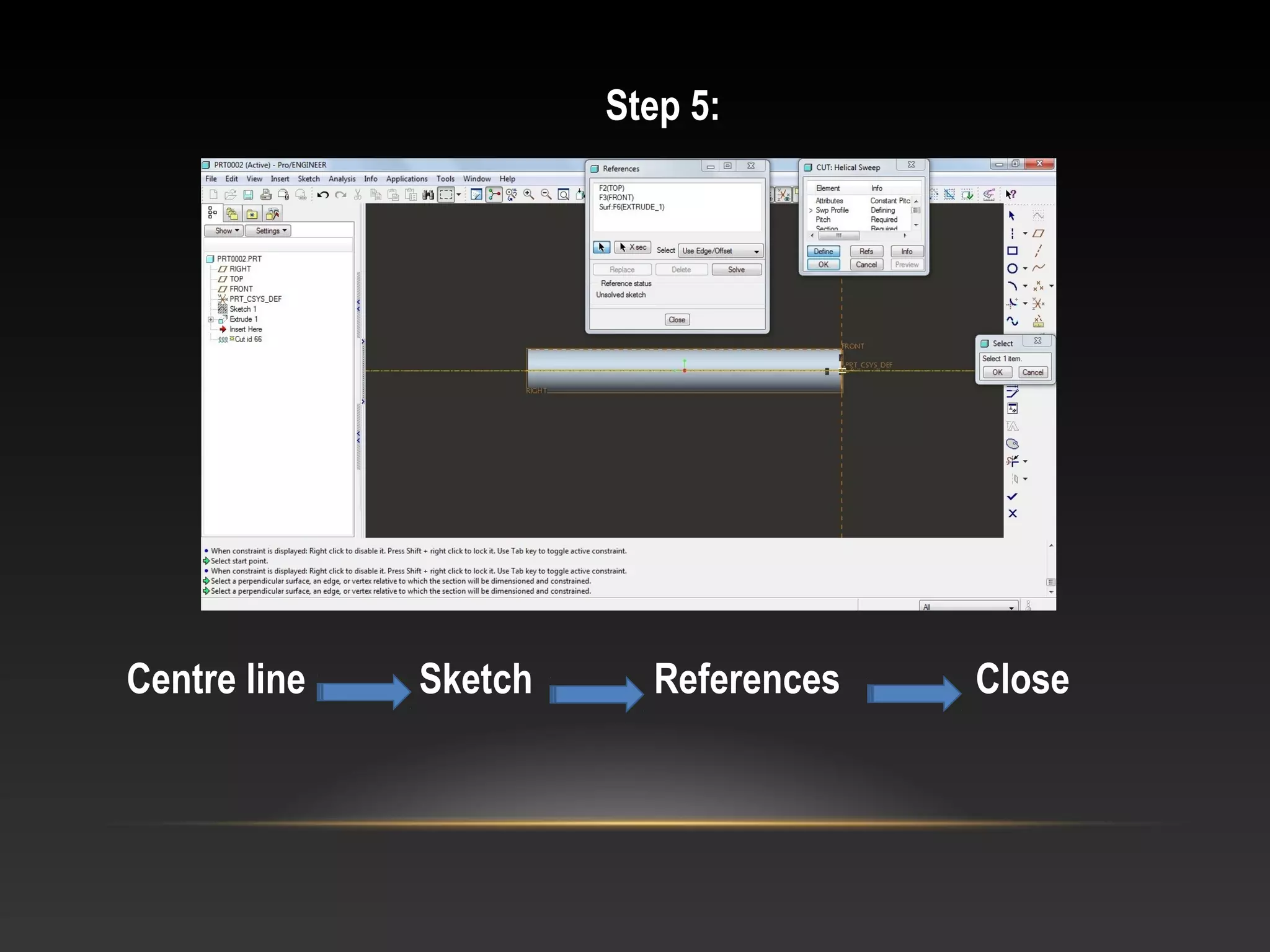
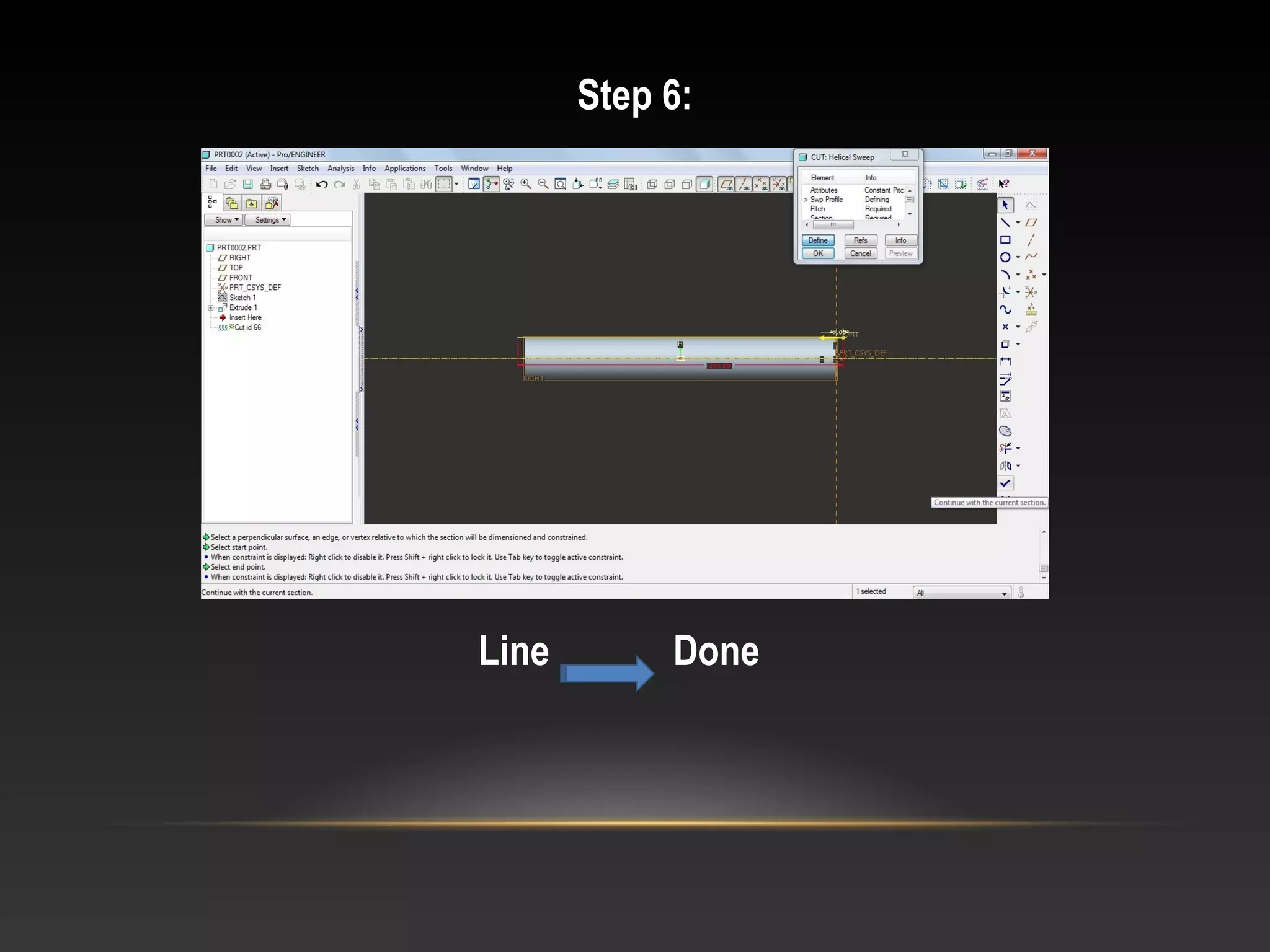
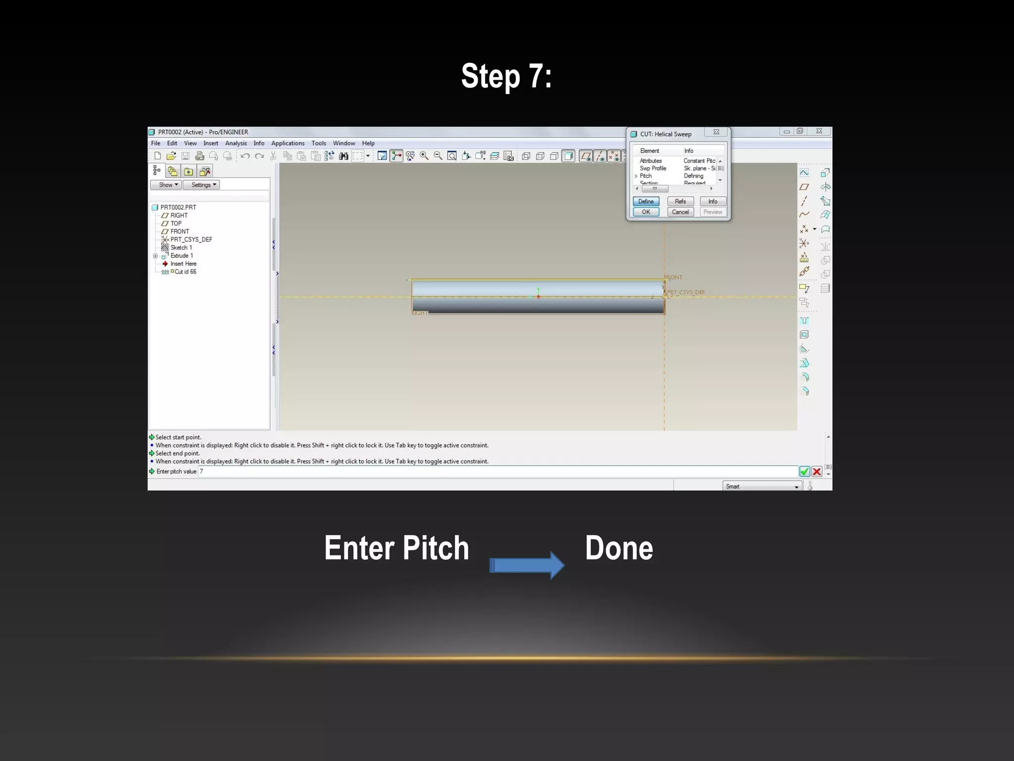
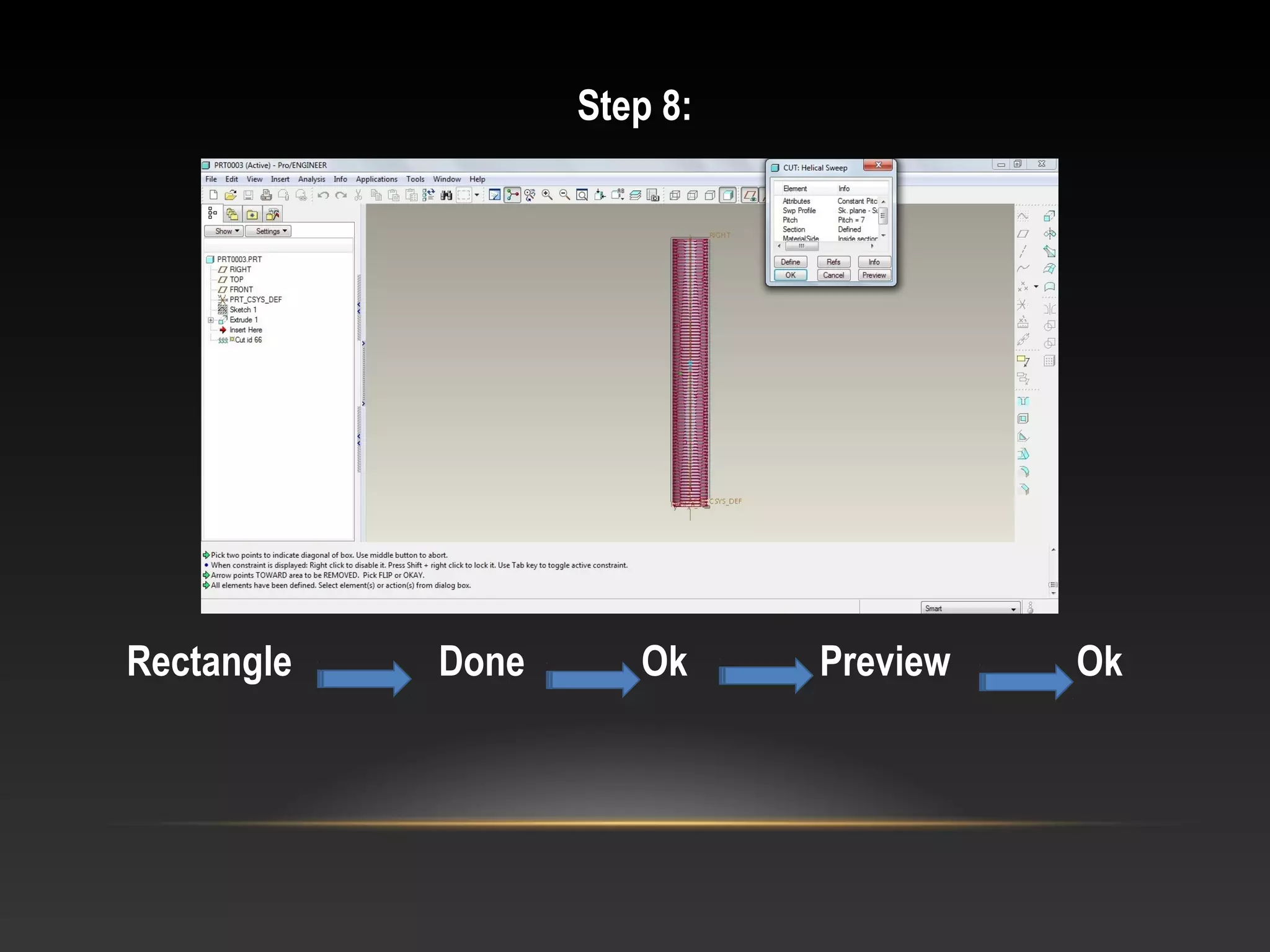
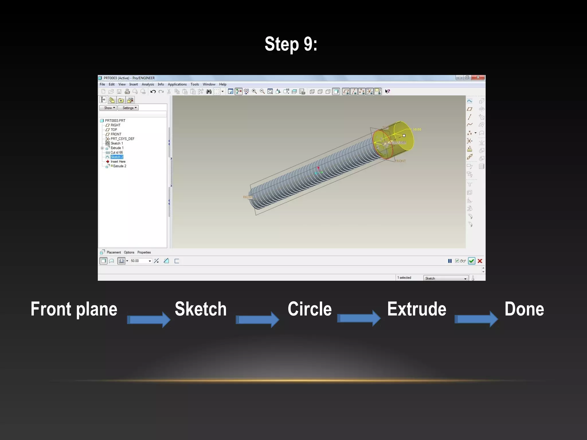
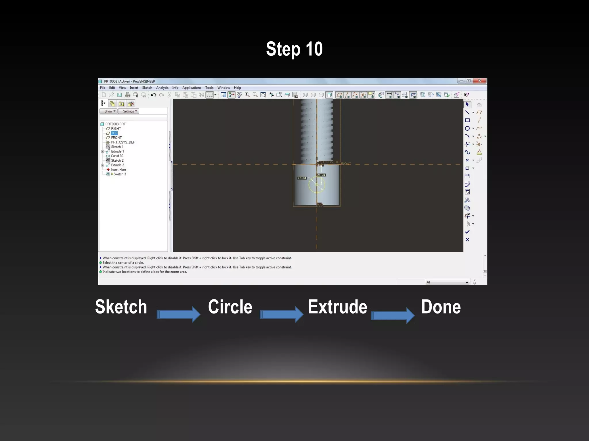
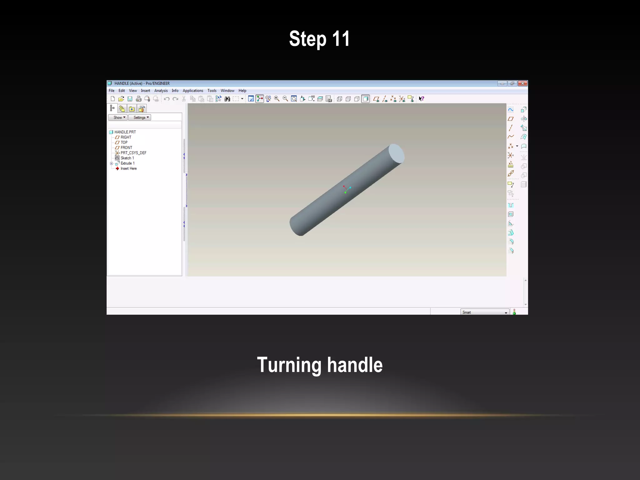
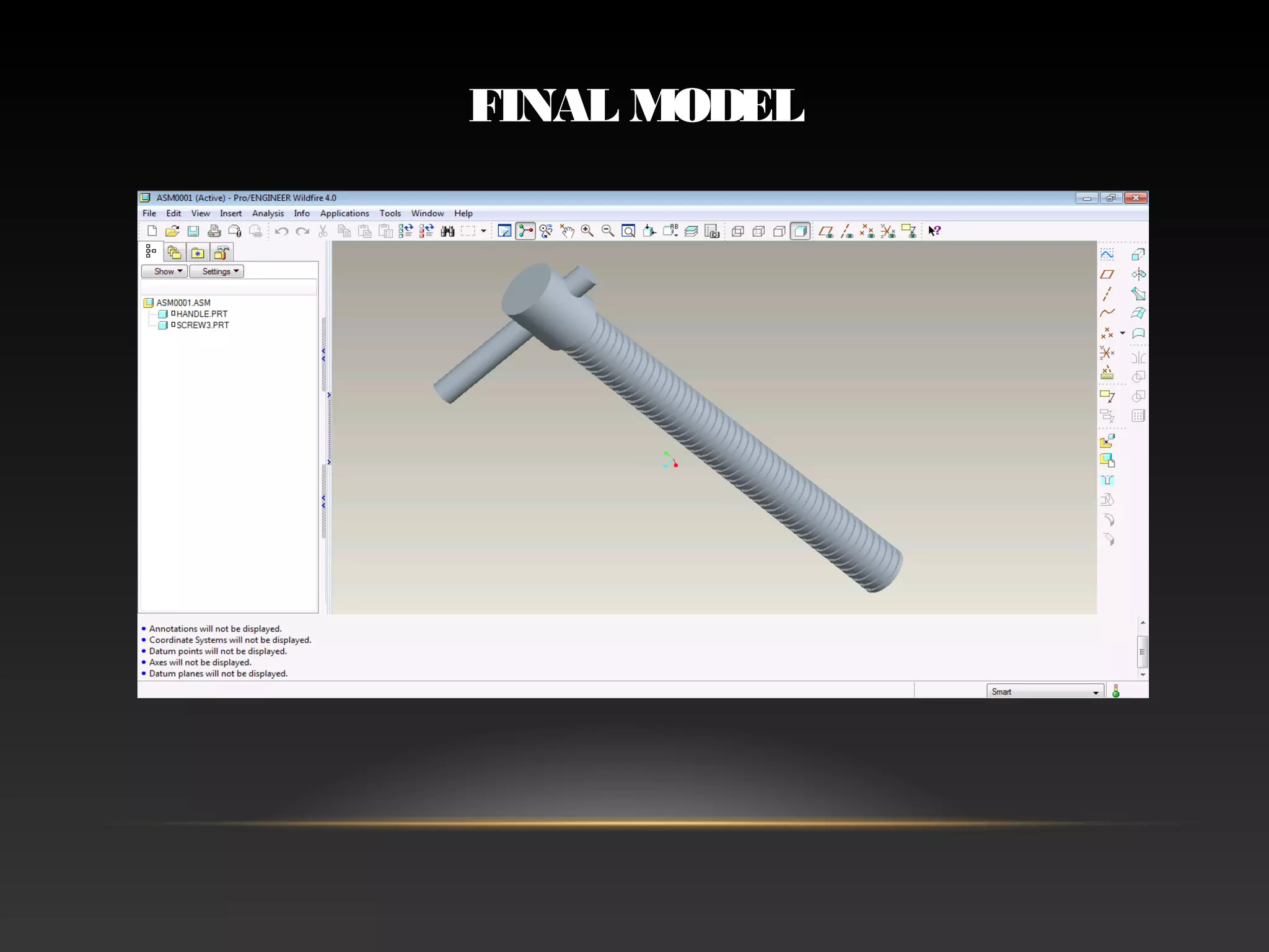
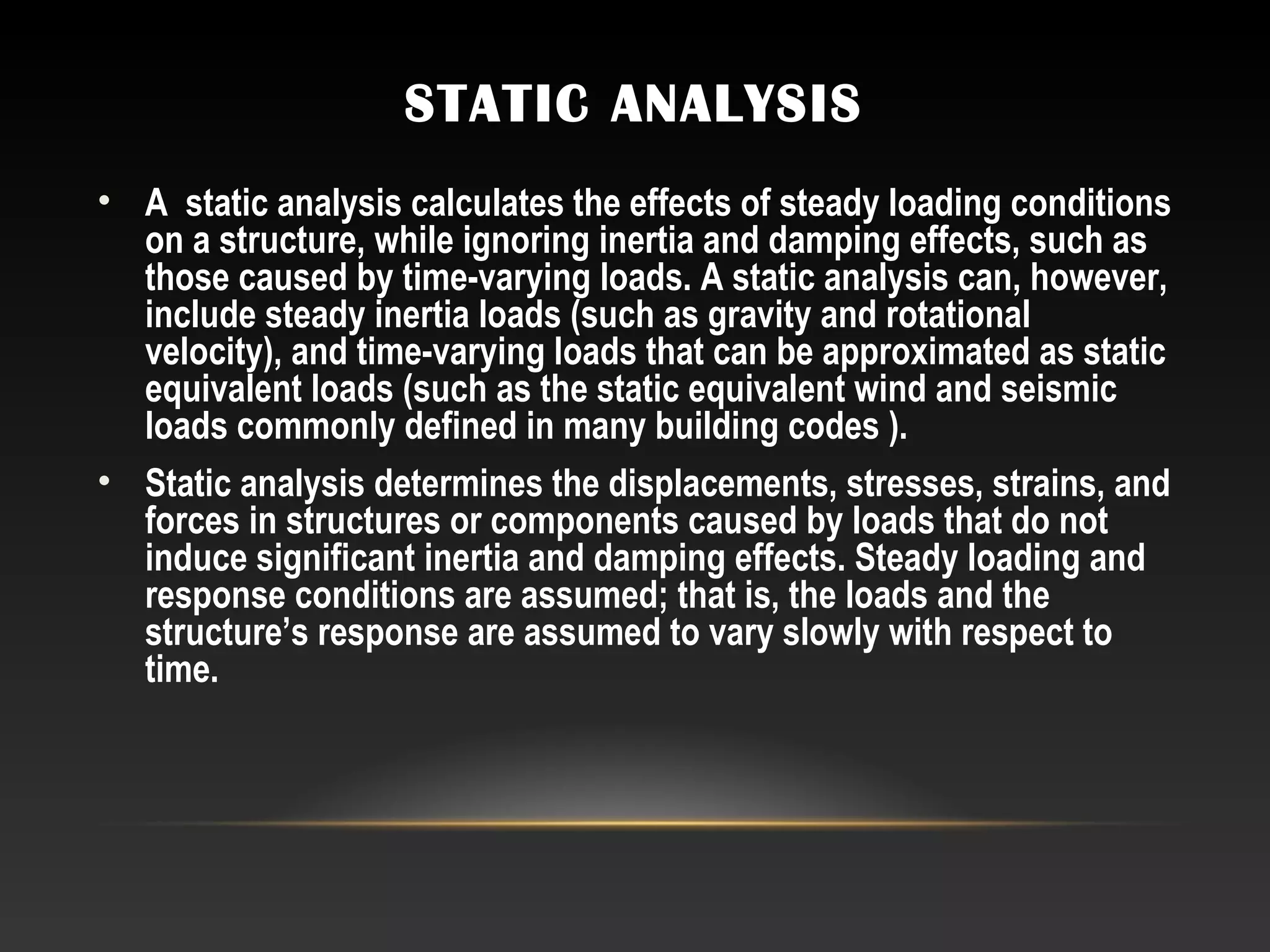
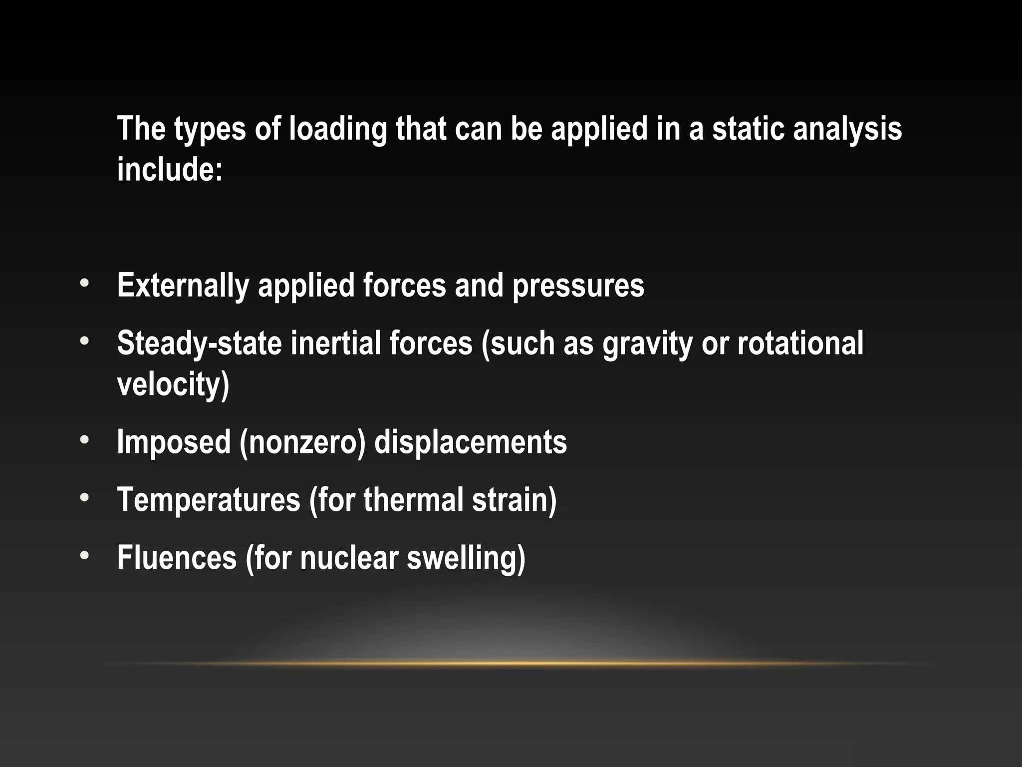
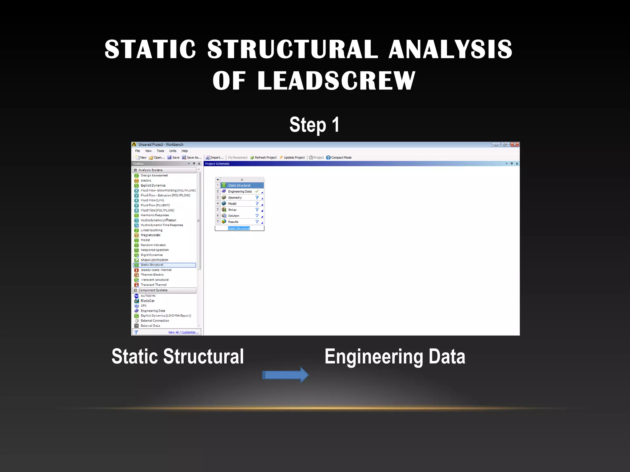
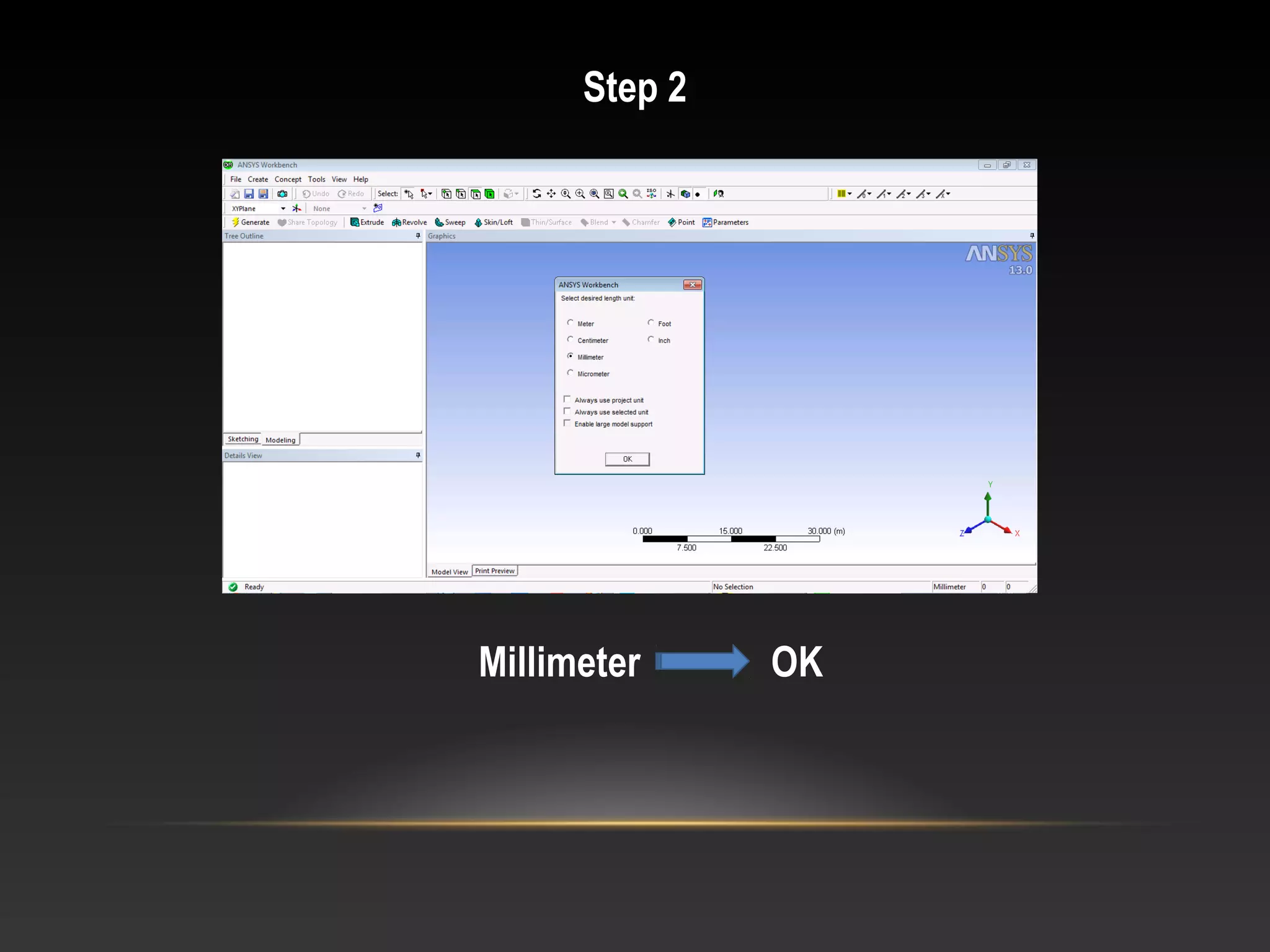
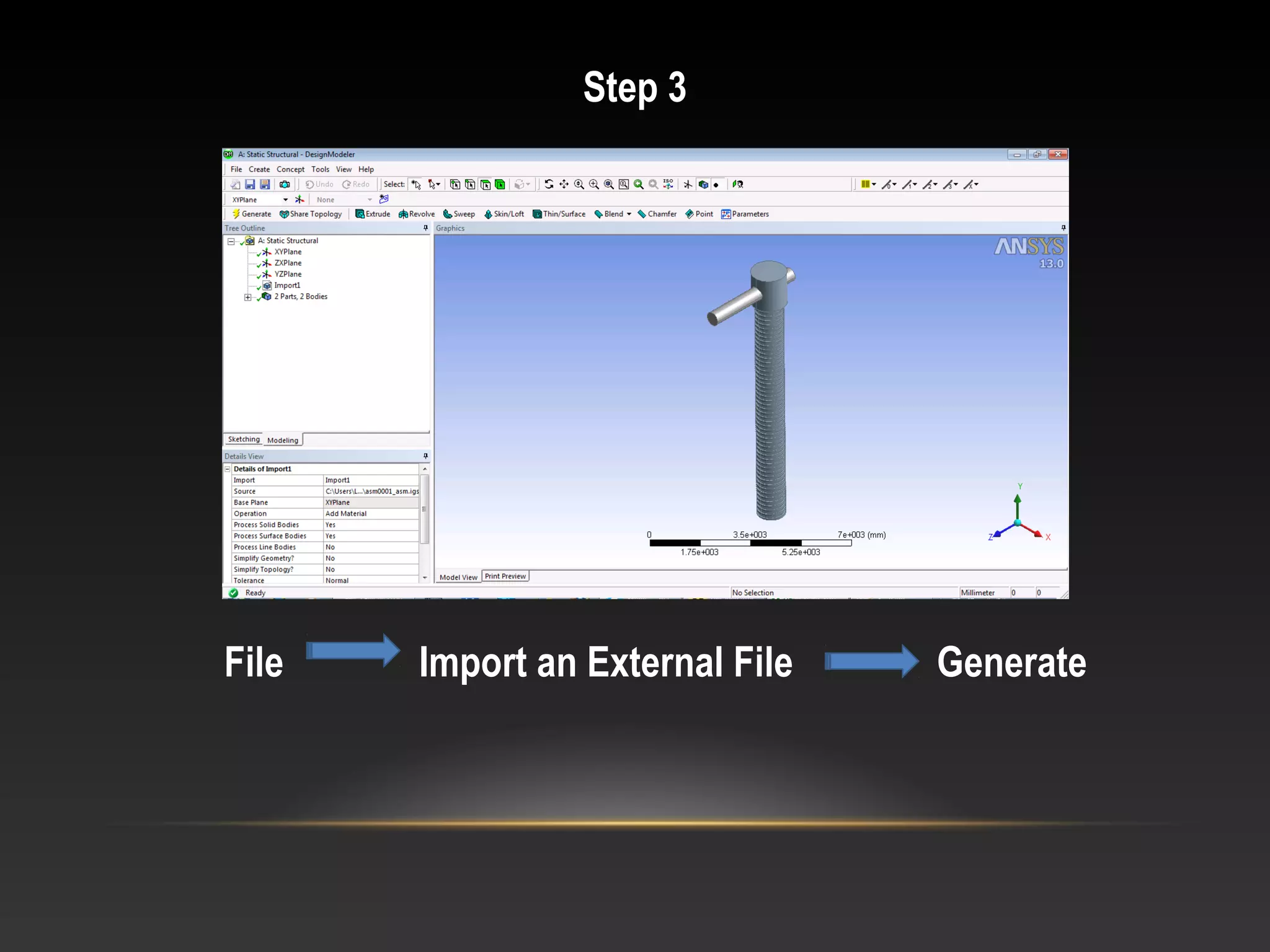
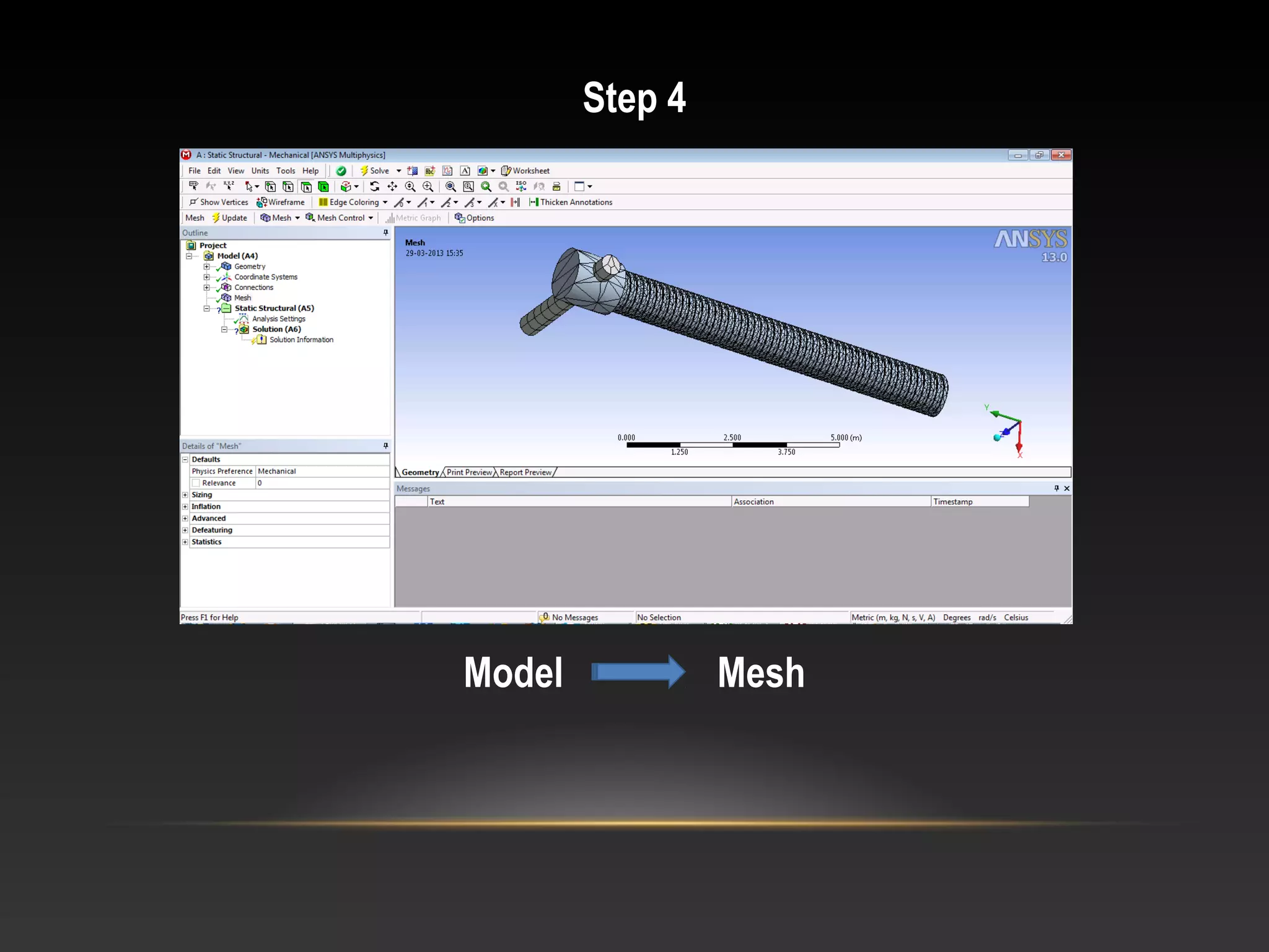
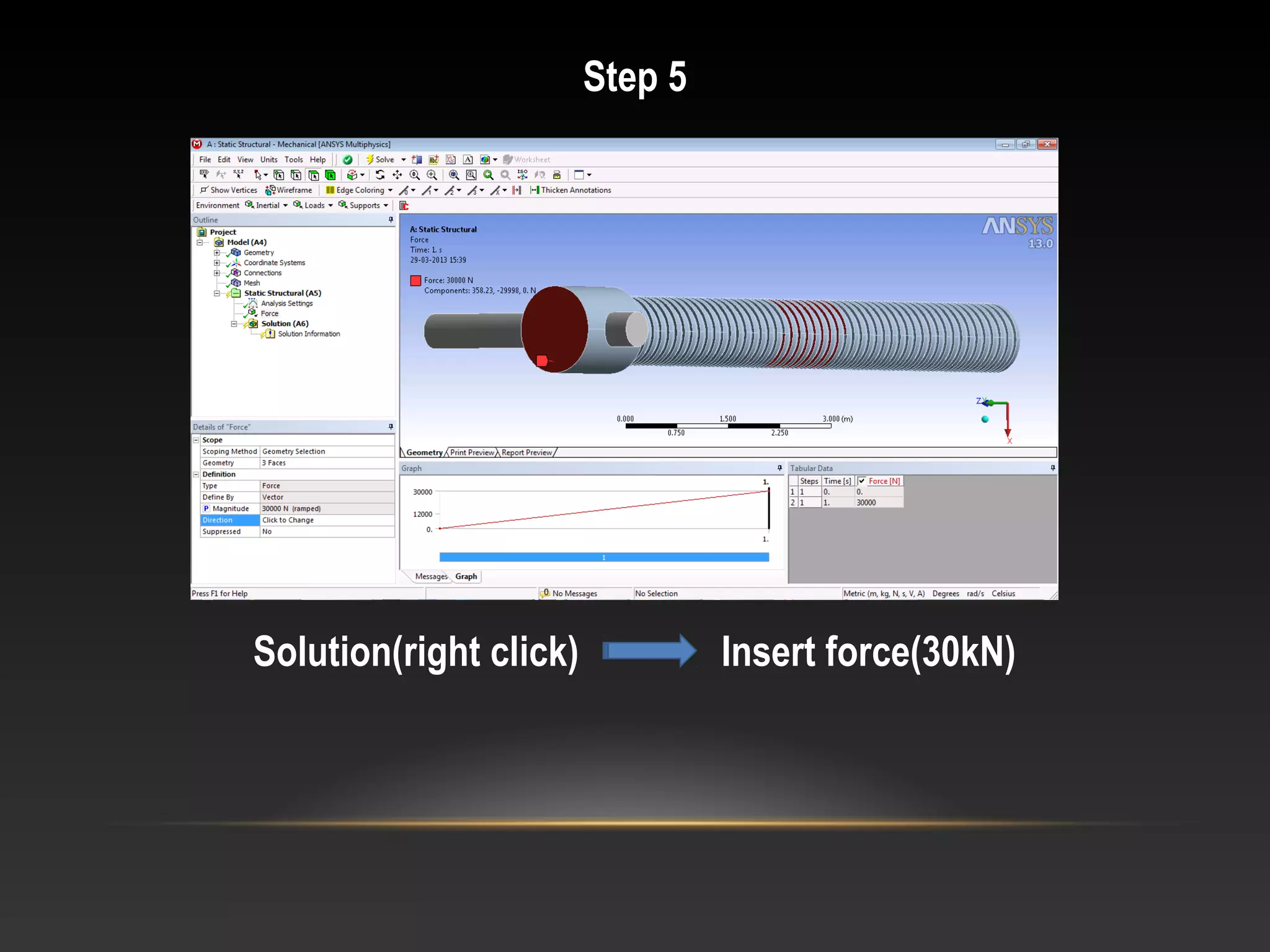
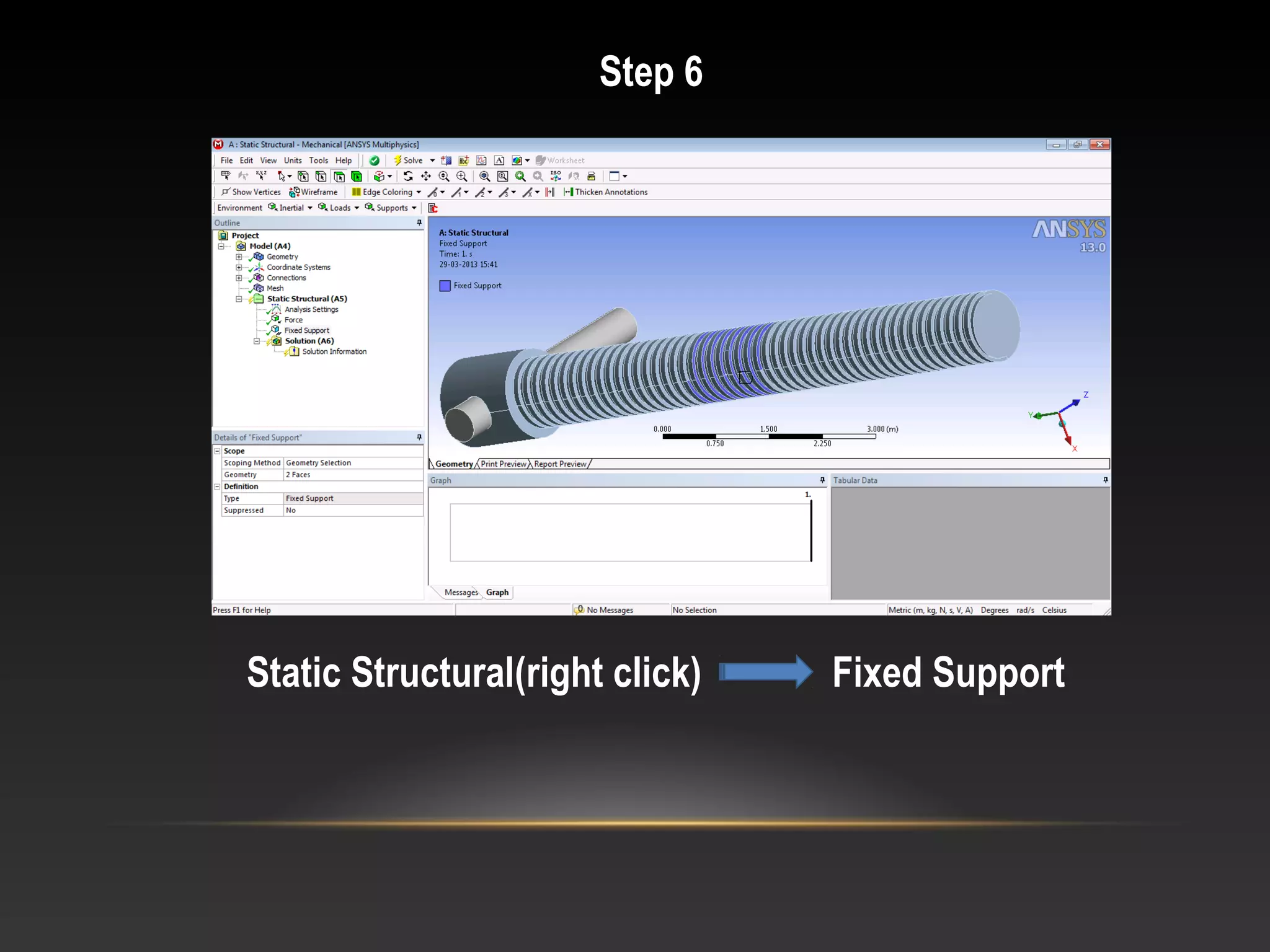
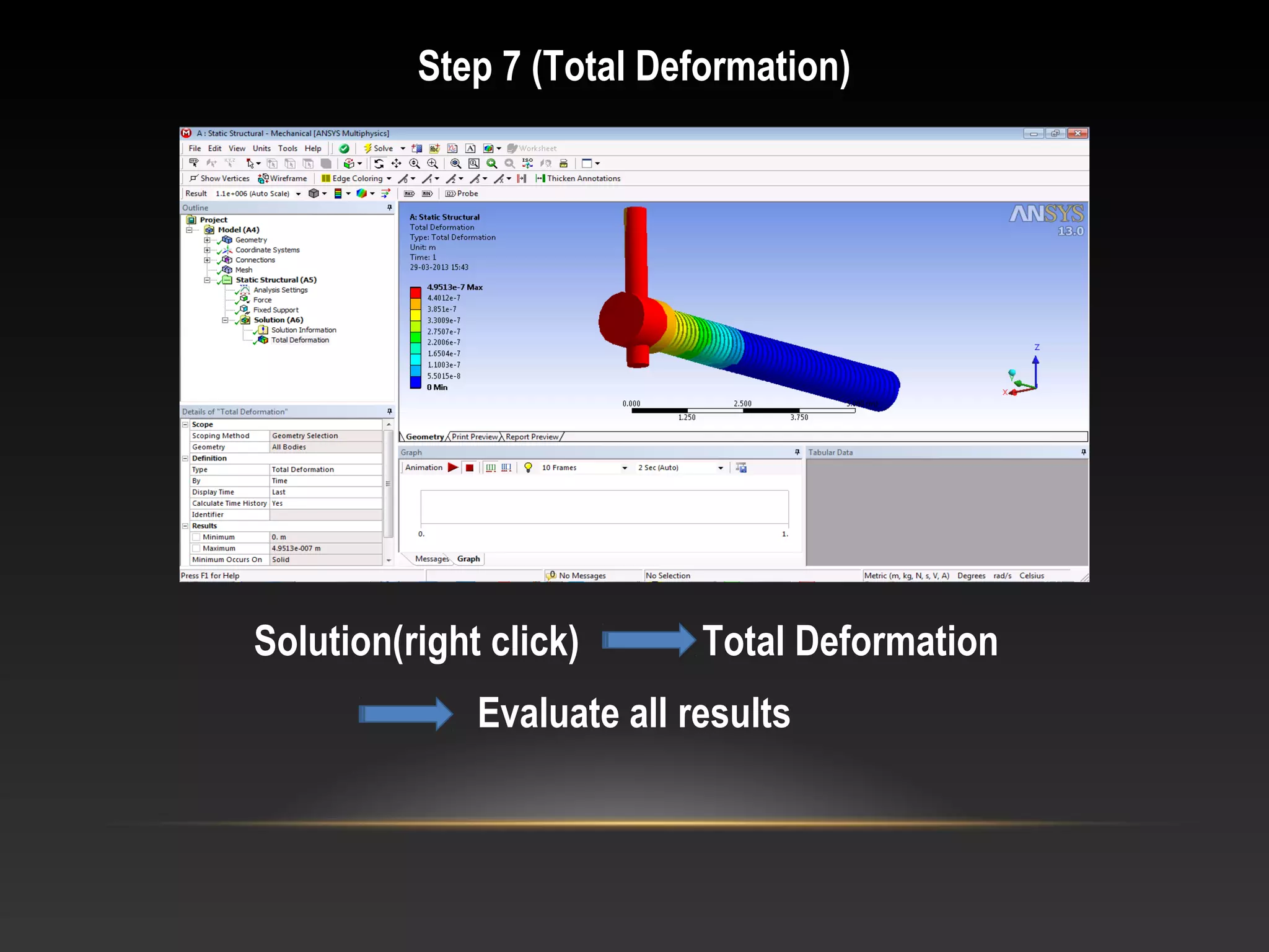
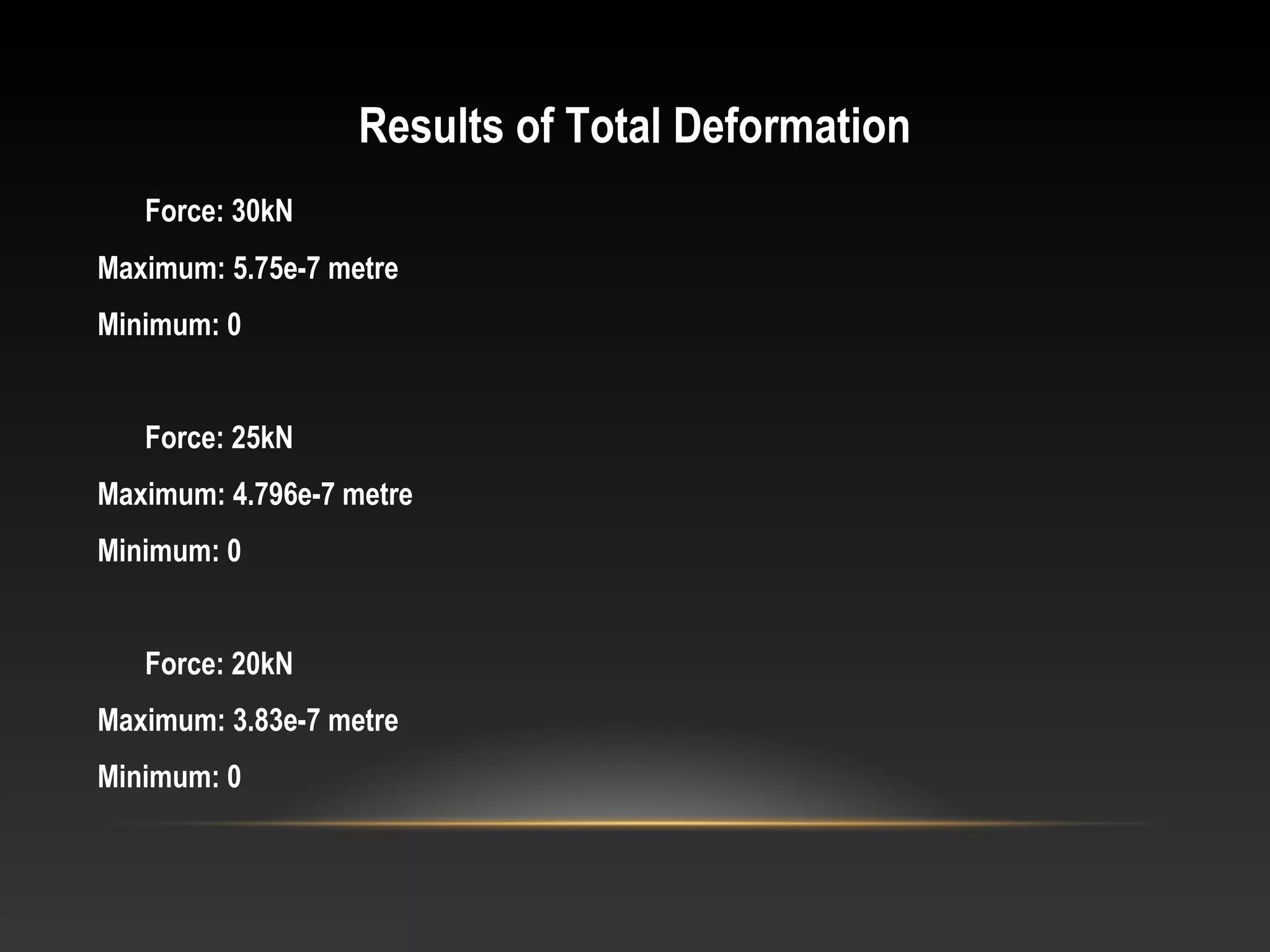
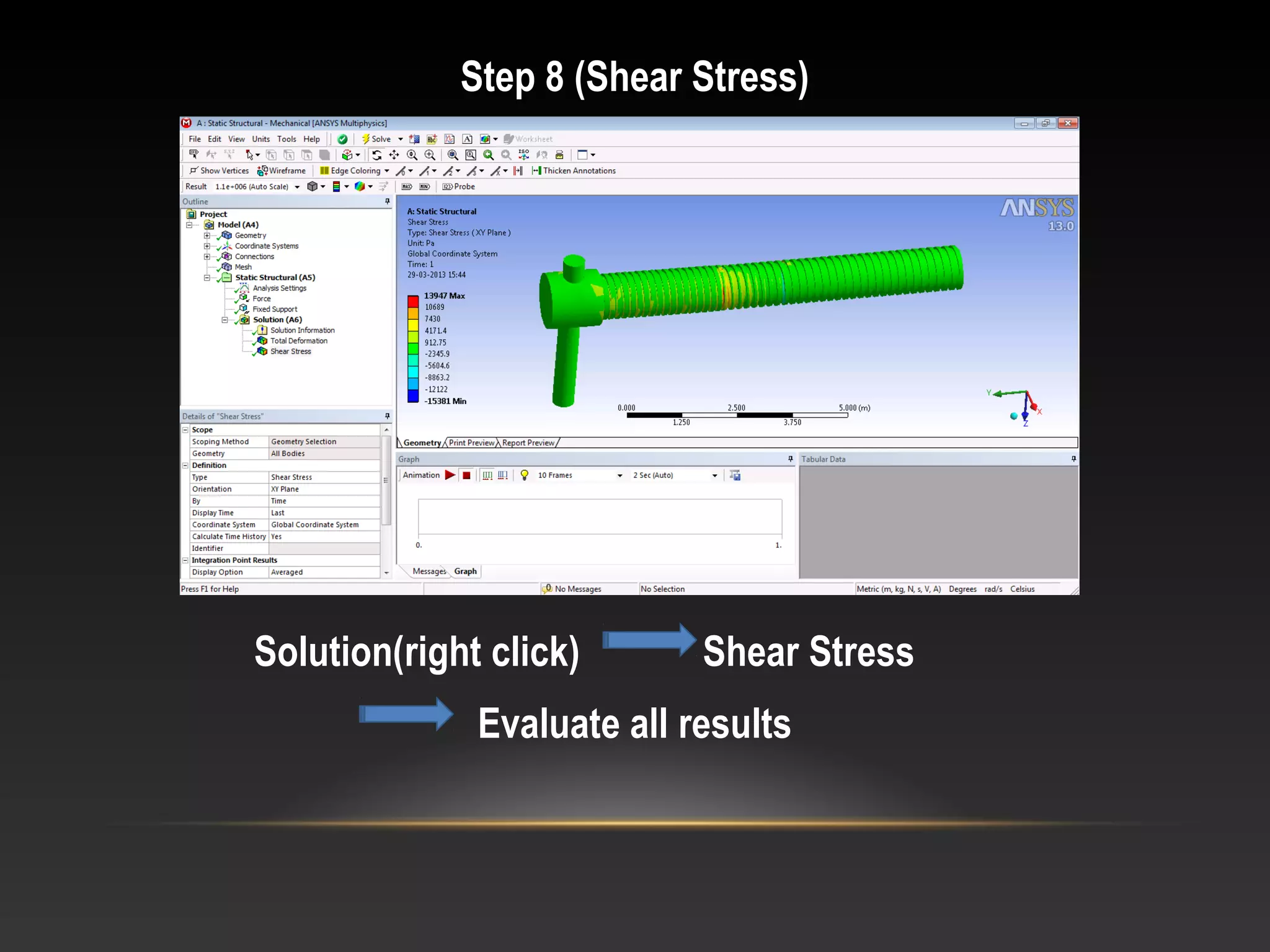
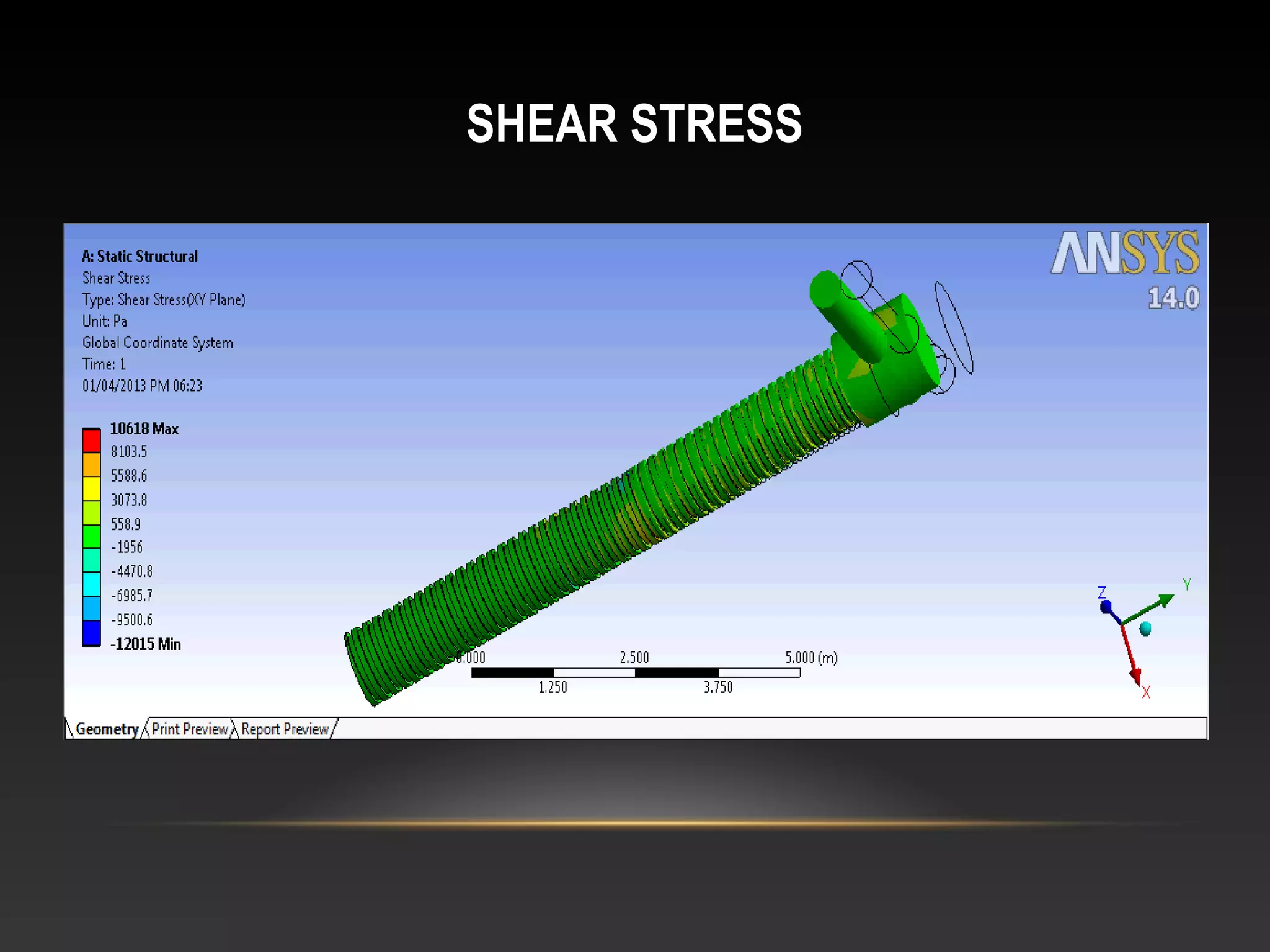
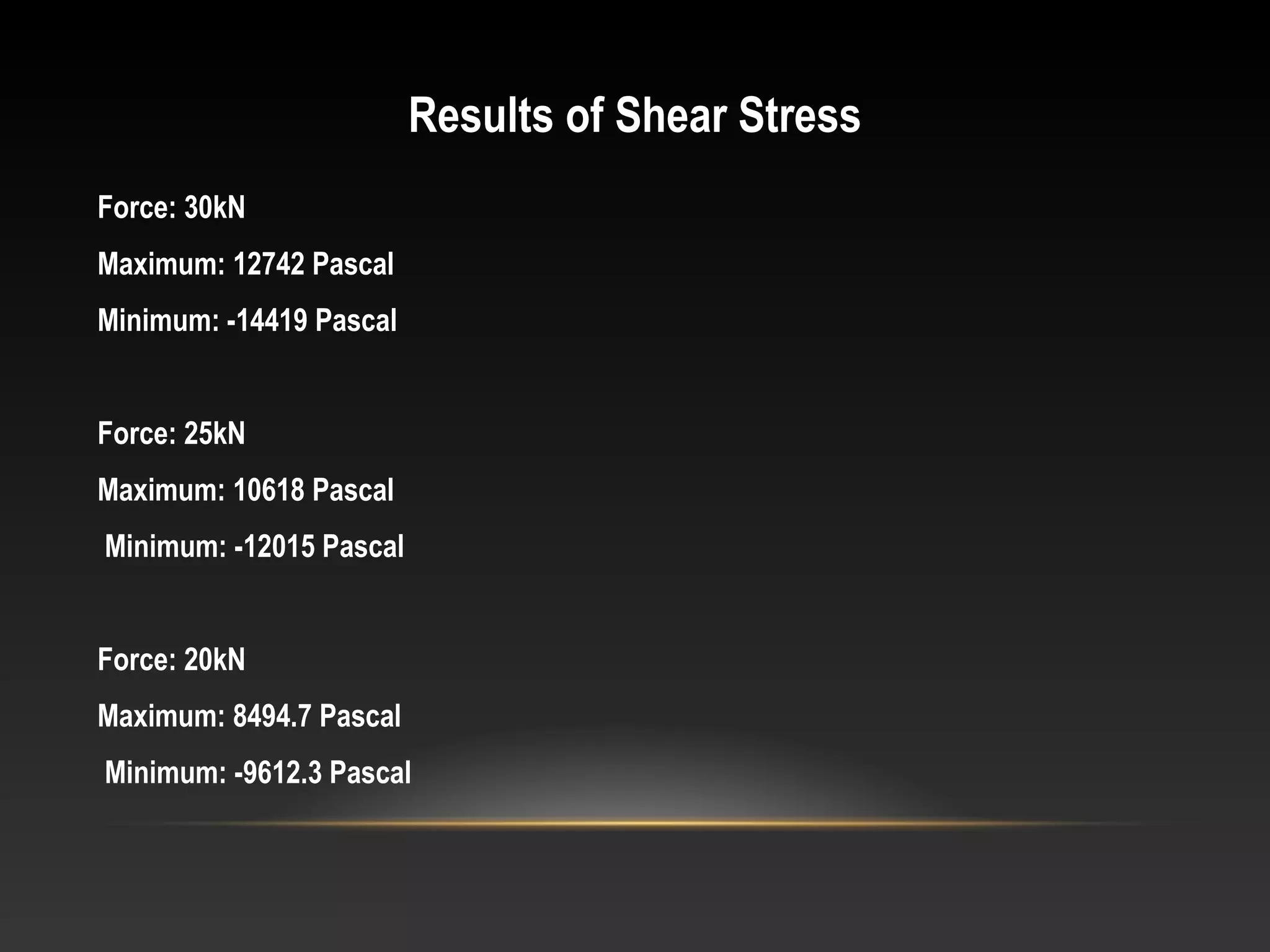
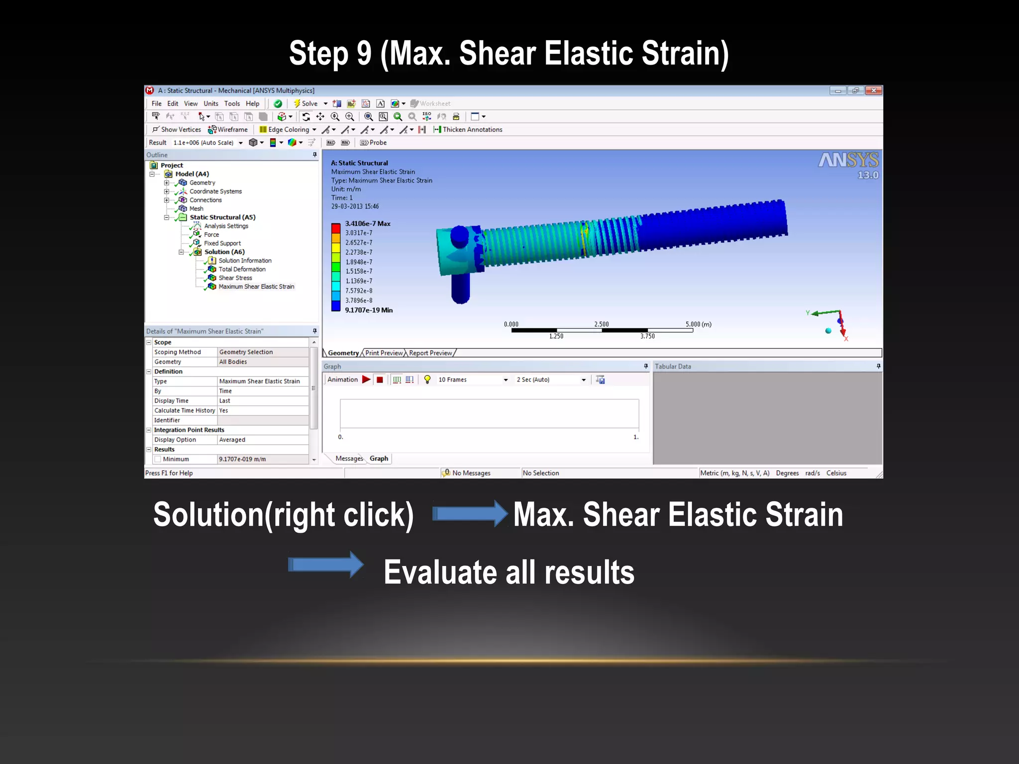
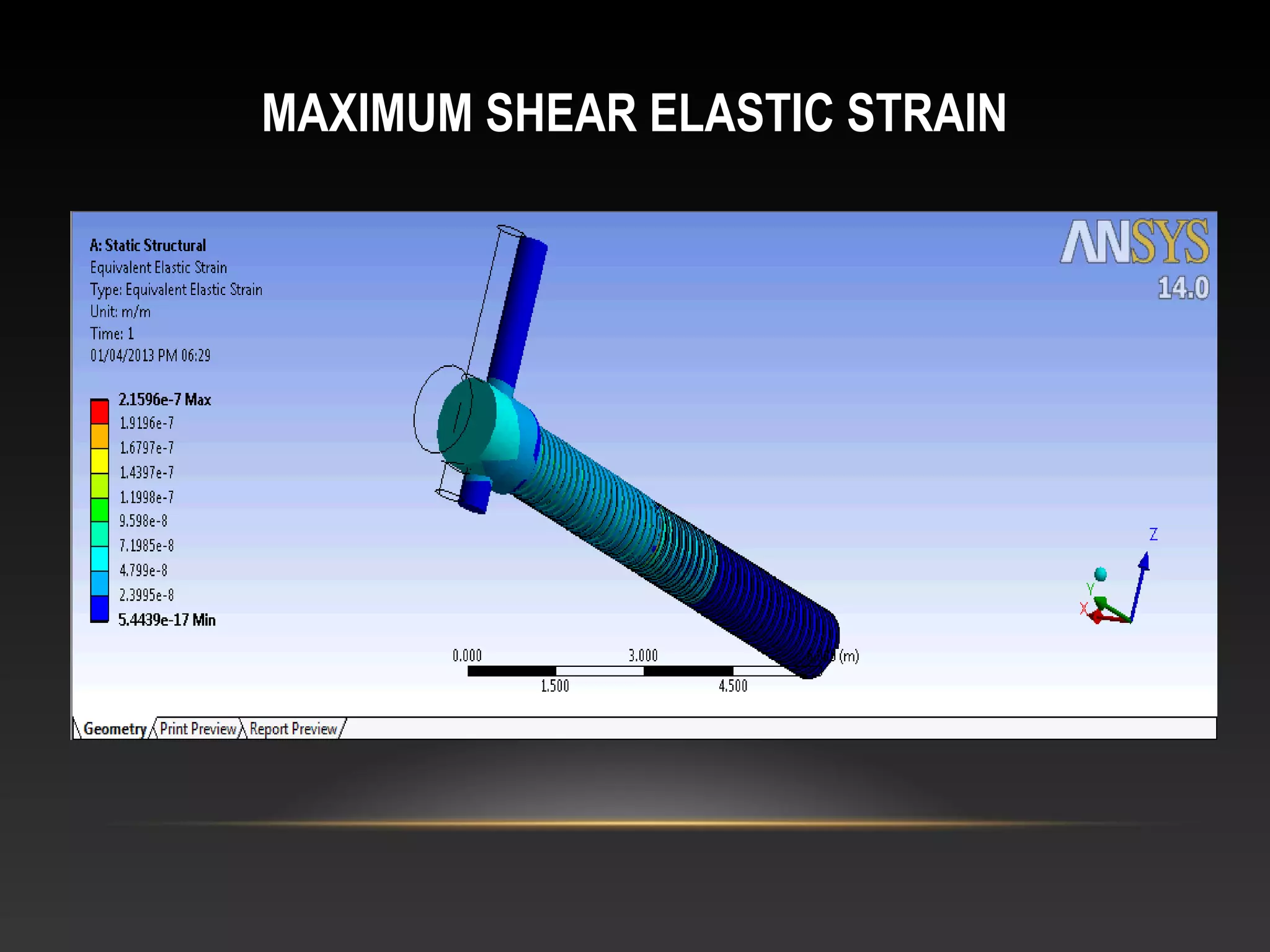
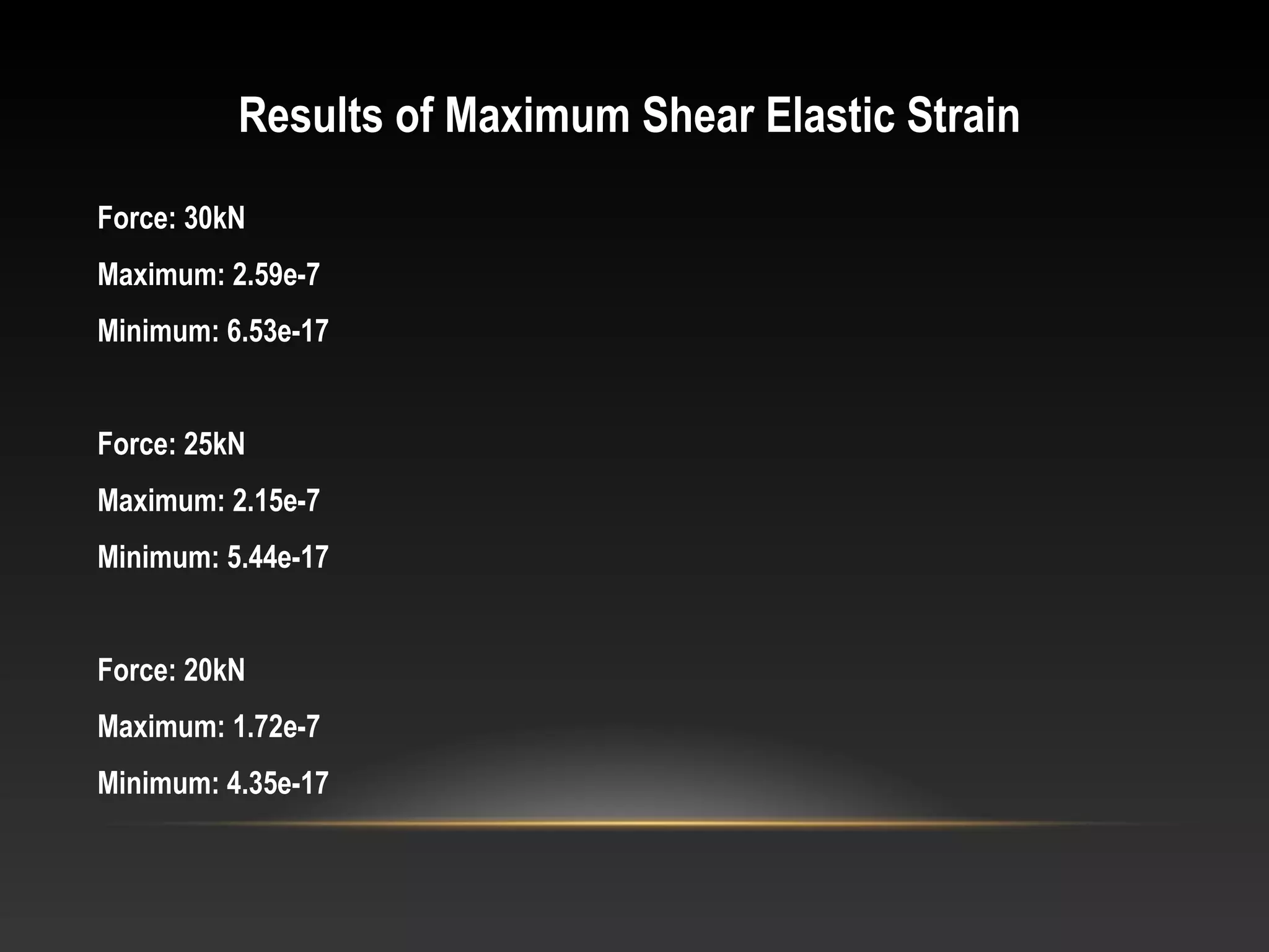
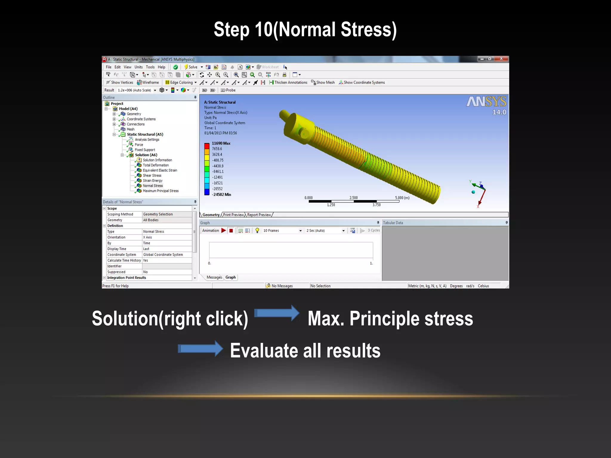
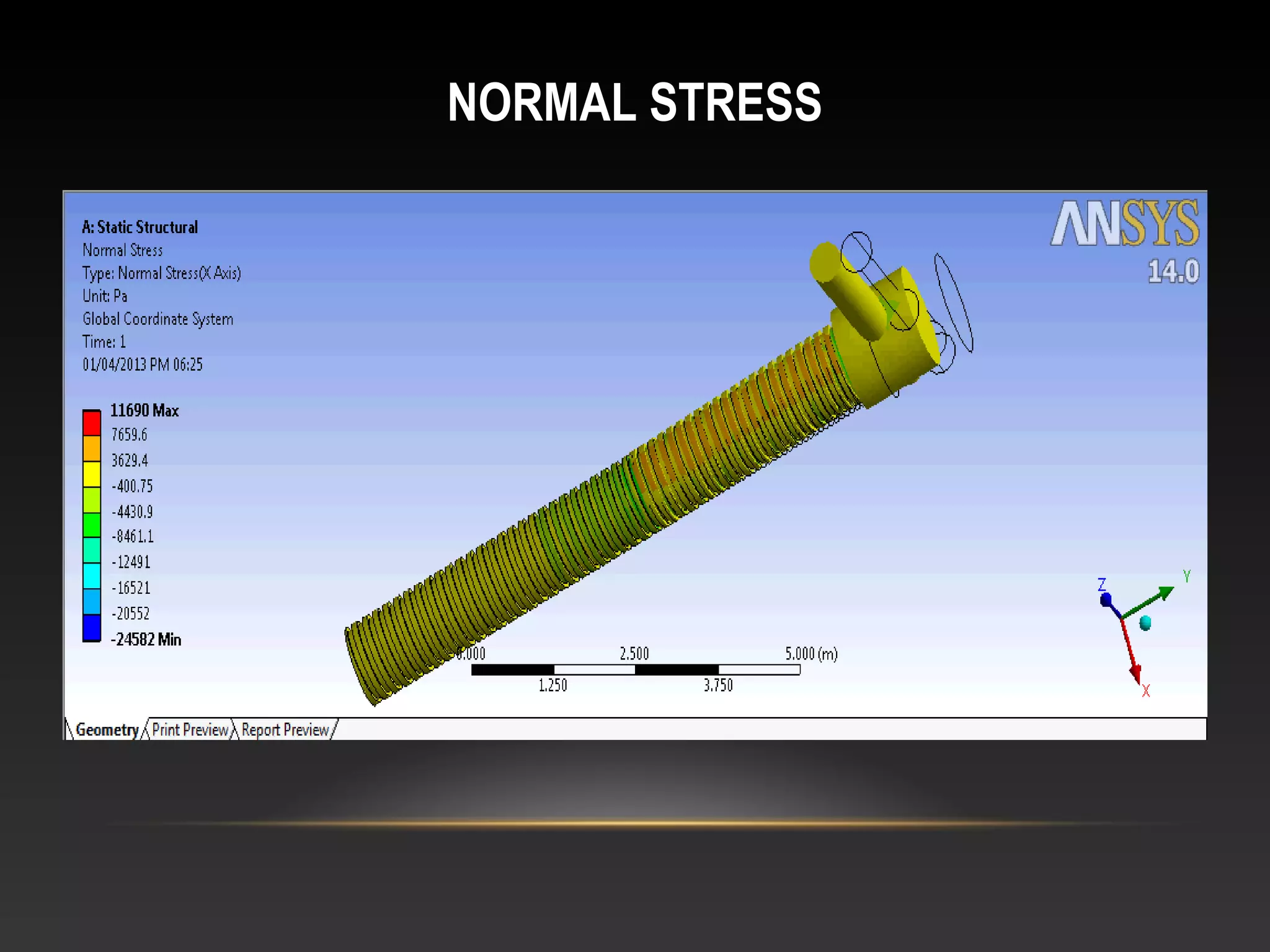
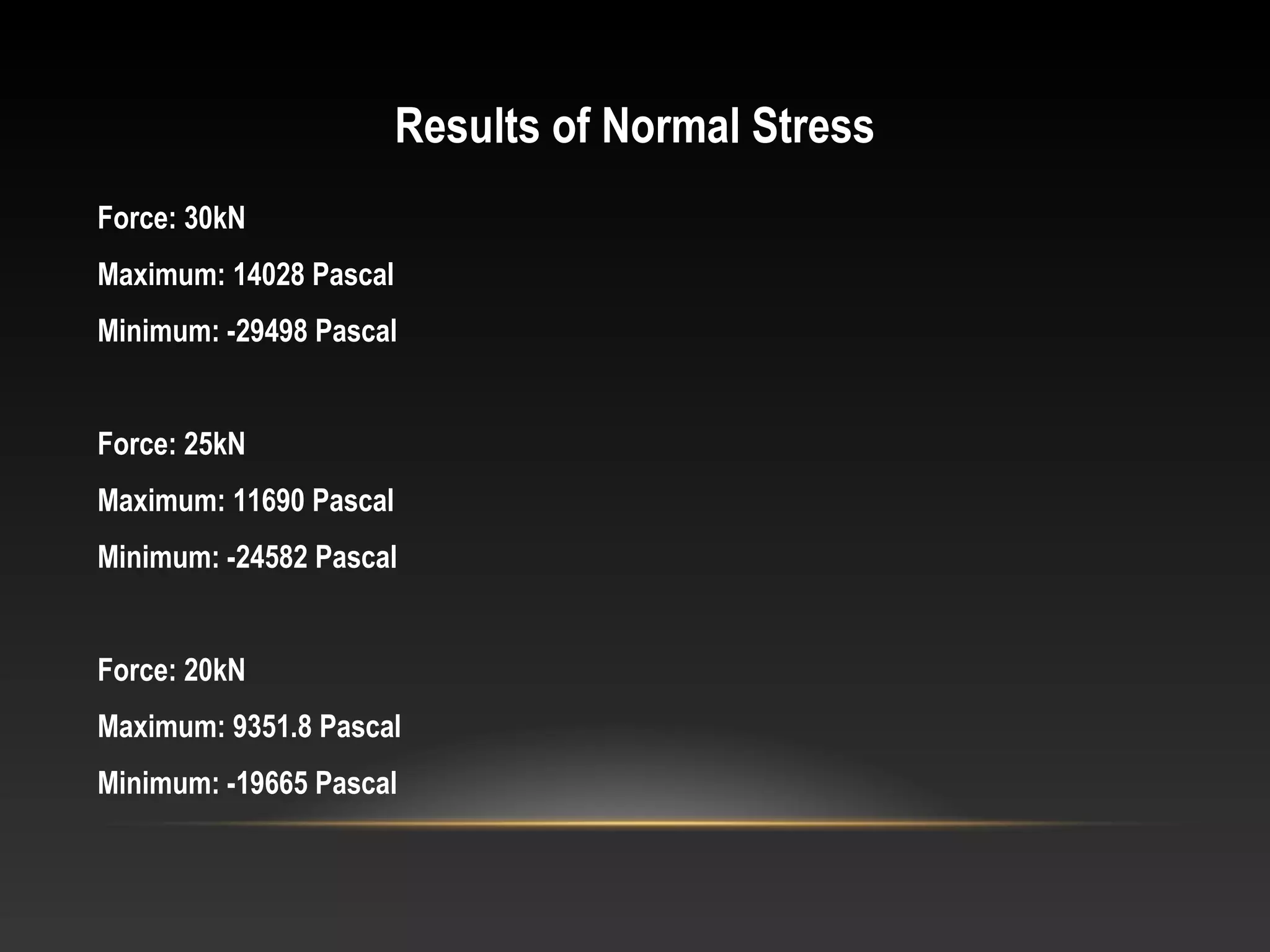
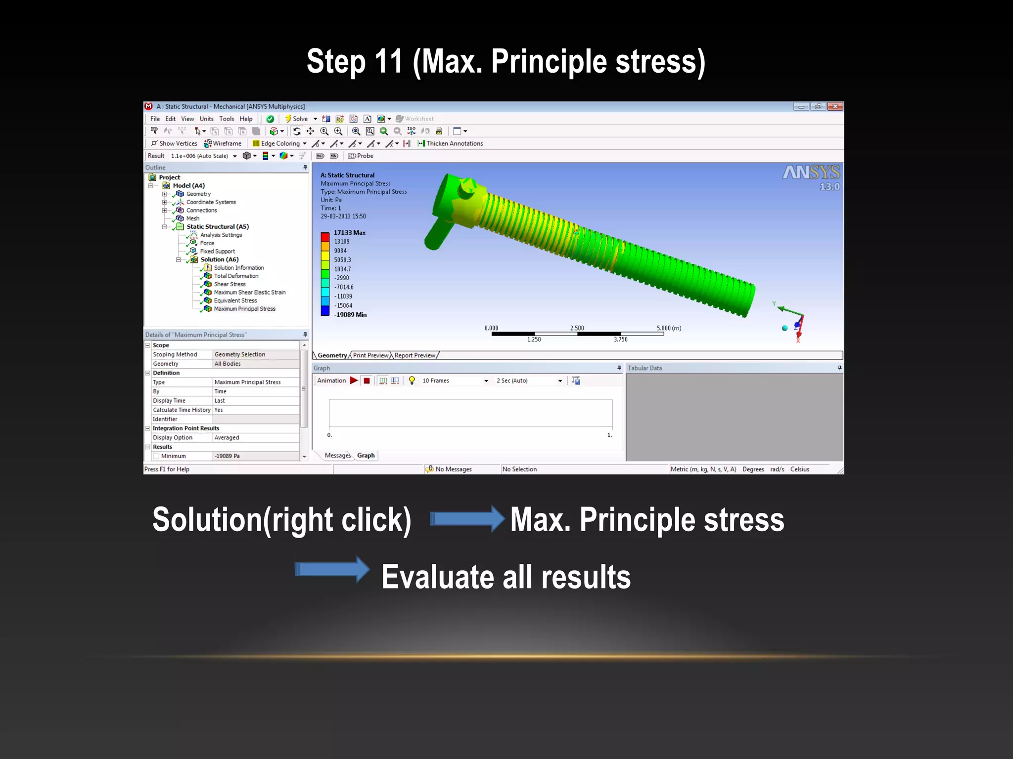
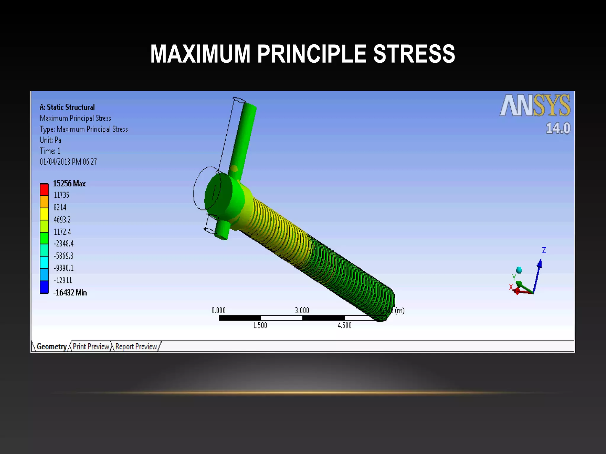
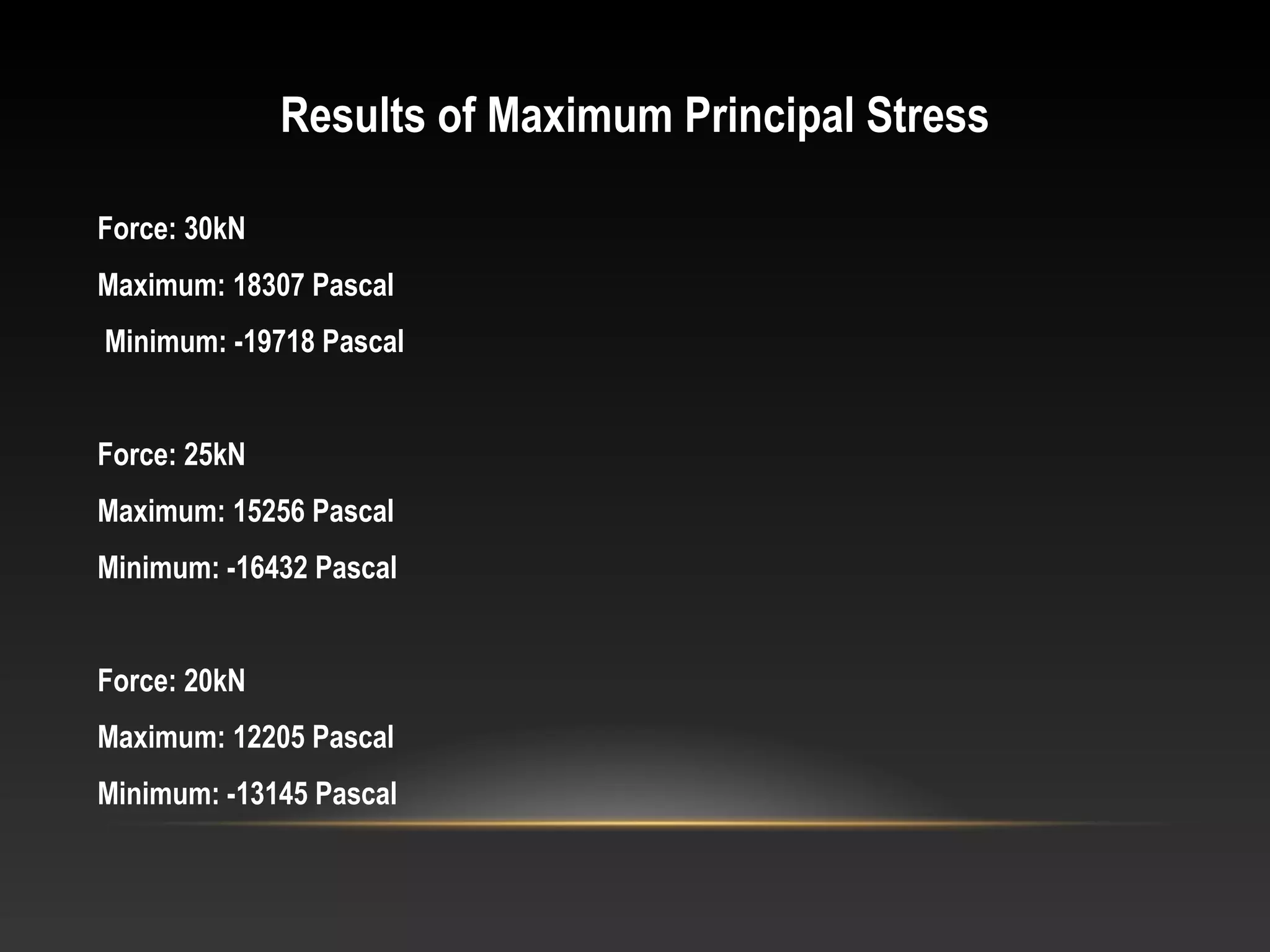
1. SHIVAJIRAO S. JONDHALE COLLEGE OF ENGINEERING
DOMBIVLI(E)
DESIGN AND ANALYSIS OF LEADSCREW
Presented by :
1. Madhushri Bardhan
2. Siddhesh Sawant
3. Sanket Chakke
4. Harshad Narvekar
Guided by : Prof. A.D. Dhale
2. CONTENTS
Objective
Literature Review
Introduction to Leadscrew
Terminology of Leadscrew
Application of Leadscrew
Screw Jack
Design of Leadscrew
Introduction to PRO/E
Modelling of Leadscrew using PRO/E
Introduction to ANSYS
Static Analysis
Static Structural Analysis of Leadscrew
Conclusion
3. OBJECTIVE
• The primary objective of our Project is the design of Leadscrew based on the
forces and the stresses developed in the component.
• Analysis of the component for various forces.
• Check for failures that may occur due to application of a particular force.
• The design of the component to be achieved using PRO/E.
• Analyse the component using ANSYS linked with PRO/E.
4. LITERATURE REVIEW
• The design of automotive or industrial power screw jack
involves many interrelated parameters.
• It is necessary to understand this interrelationship and
the constraints involved to obtain the optimum design of
power screw jack.
• Thus, Optimization play a key role in field of engineering
application.
• In our work powerscrew is machine component is to be
optimized using the Graphical & Analysis software.
5. • It is essential to determine stresses in local areas and other
areas using three dimensional, symmetric and axisymmetric
models, the preliminary conclusion is that finite element
analysis is an extremely powerful tool for design and
optimization of power screw.
• Depending on the desired solutions, there are different
methods that offer faster run times and less error.
• The recommended methods included symmetric models
using shell elements and axisymmetric models using solid
elements.
6. • Design optimization of power screw concerns with the idea
to get optimized design dimensions of power screw to
minimize weight under given set of constraint by taking pitch
& mean diameter of as design variables and screw should be
self locking assume coeffient of friction between screw and
nut is 0.16, screw is safe in buckling, Permissible stress
should be less than or equal to yield strength/FOS, screw
should be safe in shear failure as design constraints. Further
the verification of optimized graphical solution for minimum
weight is compared with Analysis software.
7. INTRODUCTION TO LEADSCREW
• A Leadscrew also known as a power screw or translation
screw is a screw designed to translate turning motion into
linear motion.
• Power screws are classified by the geometry of their threads.
• Various types of Leadscrew threads are:
i. Square thread
ii. Acme thread
iii. Buttress thread
8. • Advantages of using a Leadscrew are:
i. Large load carrying capability.
ii. Compact, simple to design and easy to manufacture.
iii. Minimal number of parts.
iv. Smooth, quiet and low maintenance.
• Disadvantages of using a Leadscrew are:
i. They are not very efficient.
ii. They have high degree of friction on threads resulting
in quicker wear out of threads.
9. TERMINOLOGY OF LEADSCREW
•Lead: It is advance of the nut along the length of the screw
per revolution.
•Pitch: Distance between corresponding points on adjacent
thread forms.
•Number of starts: It is the number of helical grooves cut
into the length of the shaft.
10. • Pitch diameter: It is the diameter at which each pitch is
equally divided between the mating male
and female threads.
• Major diameter: It is the largest diameter over the threaded
section.
• Minor diameter: It is the smallest diameter over the
threaded section.
11. APPLICATION OF LEADSCREW
• Engraving equipment
• Medical equipment
• Semiconductor manufacturing equipment
• Laboratory equipment
• Lathe machine
• Screw jack
13. • A screw jack is a portable device consisting of a screw
mechanism used to raise or lower the load.
• There are two types of jacks viz. Hydraulic and Mechanical.
• The rotation of the nut inside the frame is prevented by
pressing a setscrew against it.
• The screw is rotated in the nut by means of a handle which
passes through a hole in the head of the screw.
• The screw is subjected to torsional moment, compressive
force and bending moment.
14. DESIGN OF LEADSCREW
Theoretical design Calculations
•Type of Application: Screw Jack for Automobile
•Type of Screw Jack: Mechanical(Hand operated)
•Load: 3 tonnes(3000kg)
•Material: Plain Carbon Steel (C-10)
15. Dimensions:
•Type of thread: Square thread
•Number of Starts: Single start
•Pitch: 7mm
•Pitch diameter: 36mm
•Major Diameter: 40mm
•Minor diameter: 32mm
•Length of Screw: 300mm
•Helix angle: 3.5o
16. INTRODUCTION TO PRO-ENGINEER
The power to quickly deliver the highest quality, most accurate digital models –
that’s what Pro/ENGINEER is all about. As the primary design offering within
PTC’s Product Development System, Pro/ENGINEER details the form, fit and
function of products. With its seamless Web connectivity, product teams have
access to the resources, information, and capabilities they need – from
conceptual design to tooling development and machining. And, with
Pro/ENGINEER, high-fidelity digital models have full associativity, so that
product changes made anywhere can update deliverables everywhere. That’s
what it takes to achieve the digital product confidence needed before investing
significant capital in sourcing, manufacturing capacity, and volume production.
29. INTRODUCTION TO ANSYS
At ANSYS, we bring clarity and insight to customers' most complex
design challenges through fast, accurate and reliable simulation. Our
technology enables organizations to predict with confidence that their
products will thrive in the real world. They trust our software to help
ensure product integrity and drive business success through
innovation.Every product is a promise to live up to and surpass
expectations. By simulating early and often with ANSYS software, our
customers become faster, more cost-effective and more innovative,
realizing their own product promises
30. STATIC ANALYSIS
• A static analysis calculates the effects of steady loading conditions
on a structure, while ignoring inertia and damping effects, such as
those caused by time-varying loads. A static analysis can, however,
include steady inertia loads (such as gravity and rotational
velocity), and time-varying loads that can be approximated as static
equivalent loads (such as the static equivalent wind and seismic
loads commonly defined in many building codes ).
• Static analysis determines the displacements, stresses, strains, and
forces in structures or components caused by loads that do not
induce significant inertia and damping effects. Steady loading and
response conditions are assumed; that is, the loads and the
structure’s response are assumed to vary slowly with respect to
time.
31. The types of loading that can be applied in a static analysis
include:
• Externally applied forces and pressures
• Steady-state inertial forces (such as gravity or rotational
velocity)
• Imposed (nonzero) displacements
• Temperatures (for thermal strain)
• Fluences (for nuclear swelling)
52. Results of Maximum Principal Stress
Force: 30kN
Maximum: 18307 Pascal
Minimum: -19718 Pascal
Force: 25kN
Maximum: 15256 Pascal
Minimum: -16432 Pascal
Force: 20kN
Maximum: 12205 Pascal
Minimum: -13145 Pascal
53. CONCLUSION
• Thus we have successfully prepared the model of the
component ‘Leadscrew’ in PRO/E.
• The component has been imported in ANSYS and analysed
for various stresses.
• The component does not fail for the applied force.
• The component shows satisfactorily results for reduced
values of Forces.