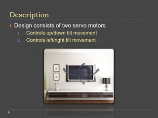
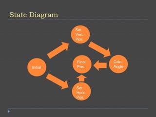
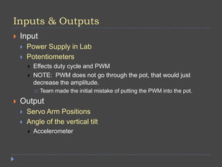
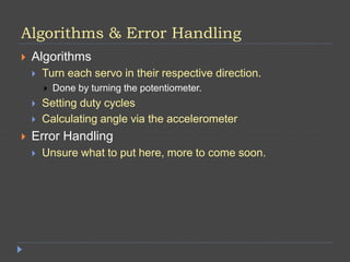
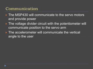
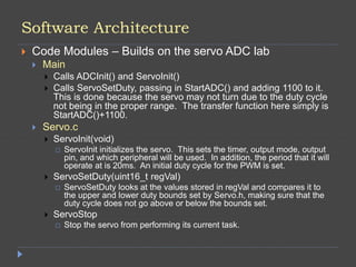
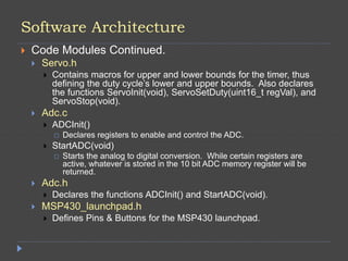
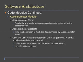
Smart Mount
Joseph Gulotta, Nicholas Parisi, Ryan Wright
Description
 Design consists of two servo motors
1. Controls up/down tilt movement
2. Controls left/right tilt movement
Requirements
 Must be able to change vertical angle
 Must be able to change horizontal angle
 Must be able to calculate the vertical angle via the
accelerometer
 Must be able to move to any position easily
Functions
 Tilt the mount up and down
 Tilt the mount right and left
 Calculate the vertical angle
 Be able to set any position easily
Resources
 1 MSP430 LaunchPad Microprocessor
 2 Servo Motors
 1 Accelerometer
 Voltage Divider Circuits
 2 Potentiometers
 Breadboard
 Wires linking the MSP430 to the breadboard
 1 Board to represent a wall
 1 board to represent the mount & monitor
 Power Supply in Lab – May eventually be changed
to an external supply
State Diagram
Set
Vert.
Pos.
Initial
Set
Horz.
Pos.
Calc.
Angle
Final
Pos.
Inputs & Outputs
 Input
 Power Supply in Lab
 Potentiometers
 Effects duty cycle and PWM
 NOTE: PWM does not go through the pot, that would just
decrease the amplitude.
 Team made the initial mistake of putting the PWM into the pot.
 Output
 Servo Arm Positions
 Angle of the vertical tilt
 Accelerometer
Algorithms & Error Handling
 Algorithms
 Turn each servo in their respective direction.
 Done by turning the potentiometer.
 Setting duty cycles
 Calculating angle via the accelerometer
 Error Handling
 Unsure what to put here, more to come soon.
Communication
 The MSP430 will communicate to the servo motors
and provide power
 The voltage divider circuit with the potentiometer will
communicate position to the servo arm
 The accelerometer will communicate the vertical
angle to the user
Coding Practices
 Neat, commented code
 Modular
 Able to be re-used easily
 No hard coding.
 Error Handling
 Informing and specific
 More to be added soon.
 Interfaces
 COBS
 ADC
Software Architecture
 Code Modules – Builds on the servo ADC lab
 Main
 Calls ADCInit() and ServoInit()
 Calls ServoSetDuty, passing in StartADC() and adding 1100 to it.
This is done because the servo may not turn due to the duty cycle
not being in the proper range. The transfer function here simply is
StartADC()+1100.
 Servo.c
 ServoInit(void)
 ServoInit initializes the servo. This sets the timer, output mode, output
pin, and which peripheral will be used. In addition, the period that it will
operate at is 20ms. An initial duty cycle for the PWM is set.
 ServoSetDuty(uint16_t regVal)
 ServoSetDuty looks at the values stored in regVal and compares it to
the upper and lower duty bounds set by Servo.h, making sure that the
duty cycle does not go above or below the bounds set.
 ServoStop
 Stop the servo from performing its current task.
Software Architecture
 Code Modules Continued.
 Servo.h
 Contains macros for upper and lower bounds for the timer, thus
defining the duty cycle’s lower and upper bounds. Also declares
the functions ServoInit(void), ServoSetDuty(uint16_t regVal), and
ServoStop(void).
 Adc.c
 ADCInit()
 Declares registers to enable and control the ADC.
 StartADC(void)
 Starts the analog to digital conversion. While certain registers are
active, whatever is stored in the 10 bit ADC memory register will be
returned.
 Adc.h
 Declares the functions ADCInit() and StartADC(void).
 MSP430_launchpad.h
 Defines Pins & Buttons for the MSP430 launchpad.
Software Architecture
 Code Modules Continued.
 Accelerometer Module
 Accelerometer Read
 Reads the x, y, and z values acceleration data gathered by the
accelerometer.
 Accelerometer Get Data
 I^2C read operation to fetch the data gathered by “Accelerometer
Read”.
 User will use “Accelerometer Get Data” to get the x, y, and z
acceleration data, and return it.
 Use a structure -- pass it in, place data in, pass it back.
 Uint16 inside structure.
Power and Grounding Management
 Power
 Powered from the computer
 Need to get a different supply.
 Grounding
 1 common ground
 Power ground
Safety Assessment
 Don’t overload the servos by putting too much
weight on the end.
 Structure must be stable and not break
 Breaking would cause damage to whatever is being held
up.
 Proper grounding
Documentation
 Lab report complete with pictures and references
 MSP 430 datasheet
 Accelerometer datasheet
 PowerPoint outlining the project
 Gantt Chart outlining our progress

Gulotta_Wright_Parisi_FinalProjectOverview1

  • 1.
    Smart Mount Joseph Gulotta,Nicholas Parisi, Ryan Wright
  • 2.
    Description  Design consistsof two servo motors 1. Controls up/down tilt movement 2. Controls left/right tilt movement
  • 3.
    Requirements  Must beable to change vertical angle  Must be able to change horizontal angle  Must be able to calculate the vertical angle via the accelerometer  Must be able to move to any position easily
  • 4.
    Functions  Tilt themount up and down  Tilt the mount right and left  Calculate the vertical angle  Be able to set any position easily
  • 5.
    Resources  1 MSP430LaunchPad Microprocessor  2 Servo Motors  1 Accelerometer  Voltage Divider Circuits  2 Potentiometers  Breadboard  Wires linking the MSP430 to the breadboard  1 Board to represent a wall  1 board to represent the mount & monitor  Power Supply in Lab – May eventually be changed to an external supply
  • 6.
  • 7.
    Inputs & Outputs Input  Power Supply in Lab  Potentiometers  Effects duty cycle and PWM  NOTE: PWM does not go through the pot, that would just decrease the amplitude.  Team made the initial mistake of putting the PWM into the pot.  Output  Servo Arm Positions  Angle of the vertical tilt  Accelerometer
  • 8.
    Algorithms & ErrorHandling  Algorithms  Turn each servo in their respective direction.  Done by turning the potentiometer.  Setting duty cycles  Calculating angle via the accelerometer  Error Handling  Unsure what to put here, more to come soon.
  • 9.
    Communication  The MSP430will communicate to the servo motors and provide power  The voltage divider circuit with the potentiometer will communicate position to the servo arm  The accelerometer will communicate the vertical angle to the user
  • 10.
    Coding Practices  Neat,commented code  Modular  Able to be re-used easily  No hard coding.  Error Handling  Informing and specific  More to be added soon.  Interfaces  COBS  ADC
  • 11.
    Software Architecture  CodeModules – Builds on the servo ADC lab  Main  Calls ADCInit() and ServoInit()  Calls ServoSetDuty, passing in StartADC() and adding 1100 to it. This is done because the servo may not turn due to the duty cycle not being in the proper range. The transfer function here simply is StartADC()+1100.  Servo.c  ServoInit(void)  ServoInit initializes the servo. This sets the timer, output mode, output pin, and which peripheral will be used. In addition, the period that it will operate at is 20ms. An initial duty cycle for the PWM is set.  ServoSetDuty(uint16_t regVal)  ServoSetDuty looks at the values stored in regVal and compares it to the upper and lower duty bounds set by Servo.h, making sure that the duty cycle does not go above or below the bounds set.  ServoStop  Stop the servo from performing its current task.
  • 12.
    Software Architecture  CodeModules Continued.  Servo.h  Contains macros for upper and lower bounds for the timer, thus defining the duty cycle’s lower and upper bounds. Also declares the functions ServoInit(void), ServoSetDuty(uint16_t regVal), and ServoStop(void).  Adc.c  ADCInit()  Declares registers to enable and control the ADC.  StartADC(void)  Starts the analog to digital conversion. While certain registers are active, whatever is stored in the 10 bit ADC memory register will be returned.  Adc.h  Declares the functions ADCInit() and StartADC(void).  MSP430_launchpad.h  Defines Pins & Buttons for the MSP430 launchpad.
  • 13.
    Software Architecture  CodeModules Continued.  Accelerometer Module  Accelerometer Read  Reads the x, y, and z values acceleration data gathered by the accelerometer.  Accelerometer Get Data  I^2C read operation to fetch the data gathered by “Accelerometer Read”.  User will use “Accelerometer Get Data” to get the x, y, and z acceleration data, and return it.  Use a structure -- pass it in, place data in, pass it back.  Uint16 inside structure.
  • 14.
    Power and GroundingManagement  Power  Powered from the computer  Need to get a different supply.  Grounding  1 common ground  Power ground
  • 15.
    Safety Assessment  Don’toverload the servos by putting too much weight on the end.  Structure must be stable and not break  Breaking would cause damage to whatever is being held up.  Proper grounding
  • 16.
    Documentation  Lab reportcomplete with pictures and references  MSP 430 datasheet  Accelerometer datasheet  PowerPoint outlining the project  Gantt Chart outlining our progress