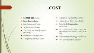
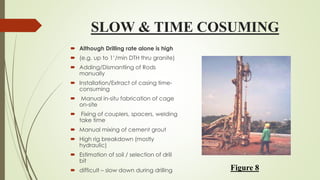
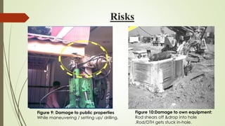
MICROPILES-
PROSPECTS & CHALLENGES
SUBMITTED BY
SUMIT RAWAT
CIVIL ENGINEERING
4TH YEAR
1202700048
CONTENT
1) INTRODUCTION
2) HISTORICAL BACKGROUND
3) CLASSIFICATIONS
4) CONSTRUCTION SQUENCES USING CASING
5) ADVANTAGES
6) DISAVANTAGES
7) APPLICATION
8) CHALLENGES
9) CONCLUSION
10) REFRENCES
INTRODUCTION
 A micropile is a small-diameter (typically less than 300 mm), drilled
and grouted replacement pile that is typically (up to 20% As/Ac)
reinforced.
 A micropile is constructed by drilling a borehole, placing
reinforcement, and grouting the hole.
 Micropiles can withstand axial and/or lateral loads.
HISTORICAL BACKGROUND
 The use of micropiles has grown significantly since their conception
in the 195Os,
 1952 - First introduced in Italy for foundation restoration
(underpinning) of WWII damaged buildings
 1960’s – Widely used in Europe for underpinning old sensitive
structures
 mid 70’s – First introduced in USA (New York &Boston)
 1980’s – Being introduced in East Asia
CLASSIFICATIONS
Based on Design Application
Based on Grouting method
Based on Design Application
 CASE 1 :- micropile elements ,which are loaded directly and where
the pile reinforcement resists the majority of the applied load.
 CASE 2 :-micropile elements circumscribes and internally
reinforces the soil to make a reinforced soil composite that resists
the applied load.
Figure 1 - 1. CASE 1 Micropiles (Directly Loaded)
Figure2-2.CASE 2 Micropiles -Reticulated Pile Network with
Reinforced Soil Mass Loaded or Engaged
Figure 3 - 1. CASE 1 Micropile Arrangements
Figure 4 -2. CASE 2 Micropile Arrangements
Based on Grouting method
 The method of grouting is generally the most sensitive construction control
over grout/ground bond capacity . Grout-to-grout capacity varies with the
grouting method.
1) Type A: Gravity Grout
2) Type B: Pressure through Casing
3) Type C: Single Global Post Grout
4) Type D: Multiple Repeatable Post Grout
 Type A: Here the grout is placed under gravity head only using
sand-cement motors or neat cement .
 TypeB:
1) In this type neat cement grout is placed into the hole as the
temporary steel casing iswith drawn.
2) Injection pressures varies from 0.5to 1.0 MPa. The pressure is
limited to avoid fracturing of the surrounding ground.
 Type C: This is done in two step process:
1) As of Type A
2) Prior to hardening of the primary grout, similar groutis injected
one time via a sleeve grout pipe at pressure of at least 1.0MPa.
 Type D: This is done in two step process of grouting similar to Type
C with modifications to step 2 where the pressure is injected at a
pressure of 2.0 to 8.0MPa:
Figure 5: Based on method of grouting
CONSTRUCTION SEQUENCES
Installation process in accordance with the requirements of NBN EN1536:1999
1) Positioning and drilling of the first section of the drill casing (recoverable
steel casing as temporary support during the boring process).
2) While drilling, the drill casing – inside equipped with a drilling head fixed
on a rod - is oscillated into the soil. (back and forth movement / twisting in
place).
3.As the drilling process progresses, soil is removed from the borehole
by the excavating and additional sections of casing are jointed (added)
to protect the soil from collapsing into the borehole during drilling..
5.After reaching the design depth, clean-up of the borehole front,
removal drilling tool, drilling fluid (water) pumped out from the bore
Formation of the pile : insertion and lowering of the reinforcement
cage, pouring of the concrete
6. During the continuous concreting process, the temporary casing
elements are progressively withdrawn whereby the concrete forms the
pile shaft.
Figure 6:Micropile construction squence’s using casing
Figure 7: Micropile construction squences using casing
CHALLENGES
 COST
 SLOW & TIME CONSUMING
 RISKS
COST
 RM$150–350 /meter
 Price Depends on :
 Reinforcement Type
 Volume (φ) of hole
 Grouting Method (any post
grouting)
 Location - Accessibility
 Length/Quantity of piles
 High Steel (up to 20% As/Ac)
 High Labour Cost – Low Prod
 Grout (NS) (+admixture)
expensive
 Fabricate cage in-situ compared
tomass production for precast RC
pile
 Specialist technology expensive
 Few players in the market
SLOW & TIME COSUMING
 Although Drilling rate alone is high
 (e.g. up to 1’/min DTH thru granite)
 Adding/Dismantling of Rods
manually
 Installation/Extract of casing time-
consuming
 Manual in-situ fabrication of cage
on-site
 Fixing of couplers, spacers, welding
take time
 Manual mixing of cement grout
 High rig breakdown (mostly
hydraulic)
 Estimation of soil / selection of drill
bit
 difficult – slow down during drilling Figure 8
Risks
Figure 9: Damage to public properties
While maneuvering / setting up/ drilling.
Figure 10:Damage to own equipment:
Rod shears off &drop into hole
.Rod/DTH gets stuck in-hole.
ADVANTAGES
 Micropiles are often used to underpin the existing structure where
need of minimal vibration or noise is of prime importance.
 Micropiles can be easily laid where low head room is a constraint.
 Micropiles can be easily installed at any angle below the horizontal
using the same equipment used for ground anchors and grouting
projects.
 Do not require large access road or drilling platforms
Figure 11: Applications
APPLICATIONS
1) Supporting New Loads in Congested Areas.
2) Seismic Retrofit.
3) Arresting Structural Settlement.
4) Resisting Uplift/Dynamic Loads.
5) Underpinning.
6) Excavation Support in Confined Areas.
CONCLUSION
 Use of Micro piles is versatile in situ ground improvement technique
and has been used very effectively in many stability problems.
 API pile system provides good compression performance in terms of
lateral stability and vertical movements.
 Tension piles can be economically reinforced by a bars system.
 Micropile can be costly option to support lateral load and bending
movement.
REFERENCE
 Armour, T, groneck, P, keeley, J and sharma, s. (2000). Micropile
design and construction guidance implementation manual. US
department and federal highway administration, FHWA-SA-97-070.
THANK YOU

Micropiles

  • 1.
    MICROPILES- PROSPECTS & CHALLENGES SUBMITTEDBY SUMIT RAWAT CIVIL ENGINEERING 4TH YEAR 1202700048
  • 2.
    CONTENT 1) INTRODUCTION 2) HISTORICALBACKGROUND 3) CLASSIFICATIONS 4) CONSTRUCTION SQUENCES USING CASING 5) ADVANTAGES 6) DISAVANTAGES 7) APPLICATION 8) CHALLENGES 9) CONCLUSION 10) REFRENCES
  • 3.
    INTRODUCTION  A micropileis a small-diameter (typically less than 300 mm), drilled and grouted replacement pile that is typically (up to 20% As/Ac) reinforced.  A micropile is constructed by drilling a borehole, placing reinforcement, and grouting the hole.  Micropiles can withstand axial and/or lateral loads.
  • 4.
    HISTORICAL BACKGROUND  Theuse of micropiles has grown significantly since their conception in the 195Os,  1952 - First introduced in Italy for foundation restoration (underpinning) of WWII damaged buildings  1960’s – Widely used in Europe for underpinning old sensitive structures  mid 70’s – First introduced in USA (New York &Boston)  1980’s – Being introduced in East Asia
  • 5.
    CLASSIFICATIONS Based on DesignApplication Based on Grouting method
  • 6.
    Based on DesignApplication  CASE 1 :- micropile elements ,which are loaded directly and where the pile reinforcement resists the majority of the applied load.  CASE 2 :-micropile elements circumscribes and internally reinforces the soil to make a reinforced soil composite that resists the applied load.
  • 7.
    Figure 1 -1. CASE 1 Micropiles (Directly Loaded)
  • 8.
    Figure2-2.CASE 2 Micropiles-Reticulated Pile Network with Reinforced Soil Mass Loaded or Engaged
  • 9.
    Figure 3 -1. CASE 1 Micropile Arrangements
  • 10.
    Figure 4 -2.CASE 2 Micropile Arrangements
  • 11.
    Based on Groutingmethod  The method of grouting is generally the most sensitive construction control over grout/ground bond capacity . Grout-to-grout capacity varies with the grouting method. 1) Type A: Gravity Grout 2) Type B: Pressure through Casing 3) Type C: Single Global Post Grout 4) Type D: Multiple Repeatable Post Grout
  • 12.
     Type A:Here the grout is placed under gravity head only using sand-cement motors or neat cement .  TypeB: 1) In this type neat cement grout is placed into the hole as the temporary steel casing iswith drawn. 2) Injection pressures varies from 0.5to 1.0 MPa. The pressure is limited to avoid fracturing of the surrounding ground.
  • 13.
     Type C:This is done in two step process: 1) As of Type A 2) Prior to hardening of the primary grout, similar groutis injected one time via a sleeve grout pipe at pressure of at least 1.0MPa.  Type D: This is done in two step process of grouting similar to Type C with modifications to step 2 where the pressure is injected at a pressure of 2.0 to 8.0MPa:
  • 14.
    Figure 5: Basedon method of grouting
  • 15.
    CONSTRUCTION SEQUENCES Installation processin accordance with the requirements of NBN EN1536:1999 1) Positioning and drilling of the first section of the drill casing (recoverable steel casing as temporary support during the boring process). 2) While drilling, the drill casing – inside equipped with a drilling head fixed on a rod - is oscillated into the soil. (back and forth movement / twisting in place).
  • 16.
    3.As the drillingprocess progresses, soil is removed from the borehole by the excavating and additional sections of casing are jointed (added) to protect the soil from collapsing into the borehole during drilling.. 5.After reaching the design depth, clean-up of the borehole front, removal drilling tool, drilling fluid (water) pumped out from the bore Formation of the pile : insertion and lowering of the reinforcement cage, pouring of the concrete 6. During the continuous concreting process, the temporary casing elements are progressively withdrawn whereby the concrete forms the pile shaft.
  • 17.
    Figure 6:Micropile constructionsquence’s using casing
  • 18.
    Figure 7: Micropileconstruction squences using casing
  • 19.
    CHALLENGES  COST  SLOW& TIME CONSUMING  RISKS
  • 20.
    COST  RM$150–350 /meter Price Depends on :  Reinforcement Type  Volume (φ) of hole  Grouting Method (any post grouting)  Location - Accessibility  Length/Quantity of piles  High Steel (up to 20% As/Ac)  High Labour Cost – Low Prod  Grout (NS) (+admixture) expensive  Fabricate cage in-situ compared tomass production for precast RC pile  Specialist technology expensive  Few players in the market
  • 21.
    SLOW & TIMECOSUMING  Although Drilling rate alone is high  (e.g. up to 1’/min DTH thru granite)  Adding/Dismantling of Rods manually  Installation/Extract of casing time- consuming  Manual in-situ fabrication of cage on-site  Fixing of couplers, spacers, welding take time  Manual mixing of cement grout  High rig breakdown (mostly hydraulic)  Estimation of soil / selection of drill bit  difficult – slow down during drilling Figure 8
  • 22.
    Risks Figure 9: Damageto public properties While maneuvering / setting up/ drilling. Figure 10:Damage to own equipment: Rod shears off &drop into hole .Rod/DTH gets stuck in-hole.
  • 23.
    ADVANTAGES  Micropiles areoften used to underpin the existing structure where need of minimal vibration or noise is of prime importance.  Micropiles can be easily laid where low head room is a constraint.  Micropiles can be easily installed at any angle below the horizontal using the same equipment used for ground anchors and grouting projects.  Do not require large access road or drilling platforms
  • 24.
  • 25.
    APPLICATIONS 1) Supporting NewLoads in Congested Areas. 2) Seismic Retrofit. 3) Arresting Structural Settlement. 4) Resisting Uplift/Dynamic Loads. 5) Underpinning. 6) Excavation Support in Confined Areas.
  • 26.
    CONCLUSION  Use ofMicro piles is versatile in situ ground improvement technique and has been used very effectively in many stability problems.  API pile system provides good compression performance in terms of lateral stability and vertical movements.  Tension piles can be economically reinforced by a bars system.  Micropile can be costly option to support lateral load and bending movement.
  • 27.
    REFERENCE  Armour, T,groneck, P, keeley, J and sharma, s. (2000). Micropile design and construction guidance implementation manual. US department and federal highway administration, FHWA-SA-97-070.
  • 28.