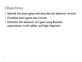
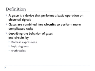
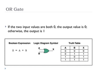
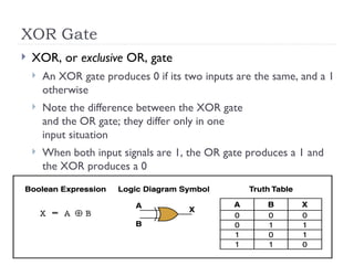
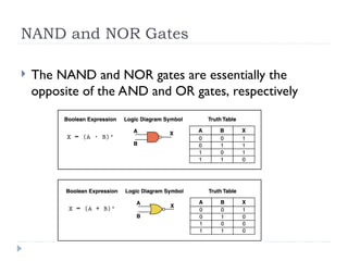
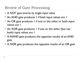
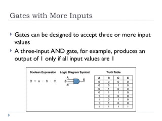
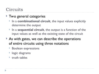
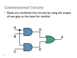
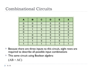
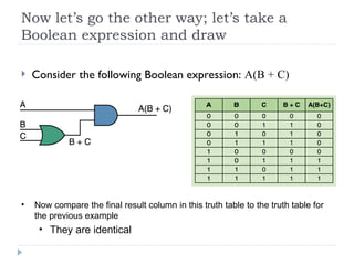
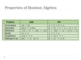
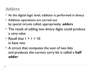
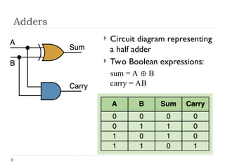
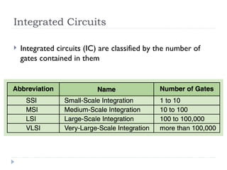
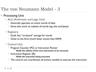
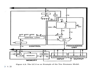
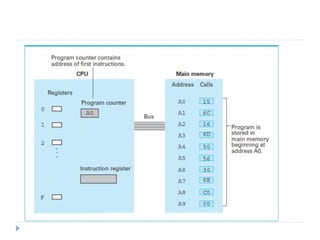
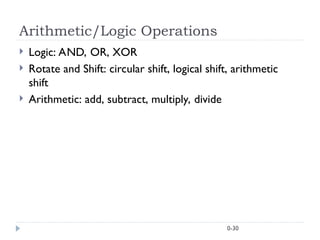
The document provides an overview of logic gates and their functionalities, including types such as NOT, AND, OR, XOR, NAND, and NOR. It explains how these gates can be combined into circuits and describes the behavior of circuits using boolean expressions, truth tables, and logic diagrams. Furthermore, it discusses the von Neumann model of computer architecture, addressing memory, processing units, integrated circuits, and the instruction cycle involved in executing instructions.

![Instructions
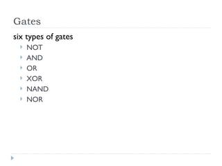
Instruction word: 16 bits
Opcode
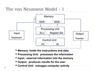
defines (names) the instruction to be executed
bits[15:12]: 4 bits allow 16 instructions
Operands
Registers: 8 registers (i.e. require 3 bits for addressing)
Address parameters: Offset (9 bits) or Index (6 bits) (more later)
Immediate value: 5 bits
Examples
ADD DR, SR1, SR2 ; DR (SR1) + (SR2)
[15:12] [11:9] [8:6] [2:0] - Note: (Reg1) means “content of Reg1”
LDR DR, BaseR, Offset ; DR Mem[BaseR + Offset]
[15:12] [11:9] [8:6] [5:0] - Note: Mem[loc] means “content of memory location loc”](https://image.slidesharecdn.com/logic-240805054304-99047b86/85/Basic-Logic-gates-and-universal-logic-gates-oerview-ppt-31-320.jpg)
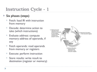
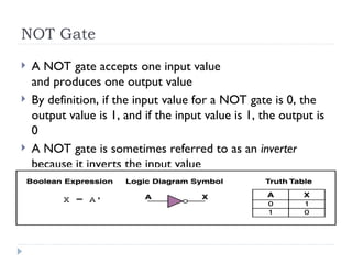
![Instruction Cycle - 2
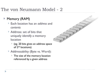
Fetch
This actually takes several steps, represented here as “micro-
instructions”, each of which can take a number of machine cycles
to implement:
MAR (PC) ; use the value in PC to access memory
MDR Mem[MAR] ; read memory location to MDR
IR (MDR) ; move (MDR) to IR
PC (PC) + 1 ; increment the value of PC
Decode
A decoder reads the opcode bit pattern & sets up the next state
of the machine to appropriately use the remaining bits of the
instruction.](https://image.slidesharecdn.com/logic-240805054304-99047b86/85/Basic-Logic-gates-and-universal-logic-gates-oerview-ppt-33-320.jpg)


![Lecture of information technology 1-COA-2015[1].pptx](https://cdn.slidesharecdn.com/ss_thumbnails/lec1-coa-20151-250806170123-c25a8fe6-thumbnail.jpg?width=640&height=640&fit=bounds)