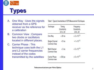
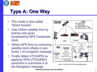
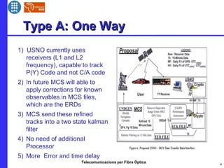
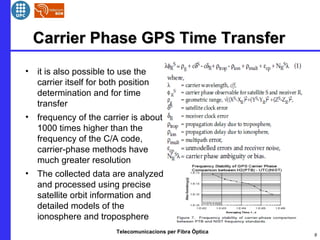
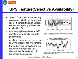
Telecomunicacions per Fibra Òptica 1
GPS Time TransferGPS Time Transfer
Yatish Bathla(Yatishbathla@gmail.com)
Bruno
Curs 2011-12
Telecomunicacions per Fibra Òptica
TypesTypes
A. One Way : Uses the signals
obtained from a GPS
receiver as the reference for
a calibration
B. Common View : Compare
two clocks or oscillators
located in different places.
C. Carrier Phase : This
technique uses both the L1
and L2 carrier frequencies
instead of the codes
transmitted by the satellites
2
Telecomunicacions per Fibra Òptica
Type A: One WayType A: One Way
• This mode is also called
“Direct Access”.
• User Obtain satellite time by
locking onto given
broadcasting GPS Composite
clock
• Obtain GPS time by correcting
satellite clock offsets in sub-
frame 1 of navigation message
• Finally obtain UTC(GPS) by
applying GPS-UTC(USNO)
correction in sub-frame 4 of
the Navigation message.
3
Telecomunicacions per Fibra Òptica
Type A: One WayType A: One Way
1) USNO currently uses
receivers (L1 and L2
frequency), capable to track
P(Y) Code and not C/A code
2) In future MCS will able to
apply corrections for known
observables in MCS files,
which are the ERDs
3) MCS send these refined
tracks into a two state kalman
filter
4) No need of additional
Processor
5) More Error and time delay
4
Telecomunicacions per Fibra Òptica
Type A: One Way ExampleType A: One Way Example
5
Telecomunicacions per Fibra Òptica
Common View GPS Time TransferCommon View GPS Time Transfer
• two different observers, separated
by large distances, observe the
same GPS satellite at the same
instant of time.
• data must be exchanged and
shared between the users.
• The final measurement result is
(Clock A - Clock B) - ( SA - SB).Ԏ Ԏ
• two types of GPS common-view
measurements:
Single - channel and multi-channel
6
Telecomunicacions per Fibra Òptica
Common View GPS Time TransferCommon View GPS Time Transfer
• Single Channel Common View requires a GPS receiver that can
read a tracking schedule.
• Multiple Channel Common View does not use a schedule. The
receiver simply records data from all satellites in view.
• Lesser time and frequency uncertainty than one way mode.
• Satellite clock errors are eliminated and Ephemeris errors are
minimized.
• No discontinuities can be seen in the data
• Measurement results are not known until after the data is
exchanged and processed
• Whole processing depends upon geometry between two users
7
Telecomunicacions per Fibra Òptica
Common View GPS Time TransferCommon View GPS Time Transfer
• T e c h n i c a l p a r a m e t e r s
• TTS-2 fully conforms to CCTF recommendations for multi-channel GPS
time transfer
• technology common-view method.
• Tracks simultaneously up to eight GPS satellites.
• Single-frequency (L1, 1575.42 MHz).
• C/A code (1.023 MHz chip rate).
• Code carrier aided tracking.
• Time interval resolution of the counter: 500 ps.
• External reference frequency 10 MHz, female BNC connector.
• Local 1 PPS input connector: female BNC.
• Antenna type: active GPS antenna (with temperature stabilisation option).
• Antenna cable length: as ordered, up to 50 m.
• Time transfer data format according to the Technical Directives for
Standardisation of
• GPS Time Receiver Software (specified in Rapport BIPM-93/6, October
1993).
• Power requirements AC 230 V ± 10%, 45 to 60 Hz or AC 110 V ± 10%, 55
to 65 Hz.
• The receiver before shipment to a user is differentially calibrated with the
uncertainty
• of a few nanoseconds with respect to the AOS time receiver calibrated by
the BIPM
8
Telecomunicacions per Fibra Òptica
Carrier Phase GPS Time TransferCarrier Phase GPS Time Transfer
• it is also possible to use the
carrier itself for both position
determination and for time
transfer
• frequency of the carrier is about
1000 times higher than the
frequency of the C/A code,
carrier-phase methods have
much greater resolution
• The collected data are analyzed
and processed using precise
satellite orbit information and
detailed models of the
ionosphere and troposphere
9
Telecomunicacions per Fibra Òptica
Carrier Phase GPS Time TransferCarrier Phase GPS Time Transfer
10
Performance
● 40 Channels Continuous/Simultaneous
● Data type: L1/L2 Code and Carrier,
GPS,
GLONASS, EGNOS, WAAS
● Data output format: CGGTTS and
RINEX
● Time interval resolution of the internal
counter 100 ps
● 0.5 V trigger level
● Time transfer precision about 1 ns;
Time transfer accuracy about 2 ns
Interfaces
● 100BASE-T Ethernet port
● USB port
● 210GB free for data storage (standard
version)
● The system is working under LINUX
providing multitasking and better
Integration with networks
● External reference frequency input:
10 MHz
● Local 1 PPS input connector: female
BNC
● Antenna cable length: as ordered, up to
50 m; TNC connector
● Power requirements AC 220 V ― 10%,
45 to 60 Hz or AC110 V }10%, 55 to
65 Hz.
Telecomunicacions per Fibra Òptica
GPS Feature(Selective Availability)GPS Feature(Selective Availability)
• To limit GPS position and velocity
accuracy available to non military
users, the Department of Defense
established a policy of Selective
Availability (SA).
• time varying biases into the GPS
signals to intentionally degrade
performance
• resulting time error can be as much
as 340 nanoseconds (95 percent).
• During both the Gulf War and the
incursion into Haiti, the DoD
directed that SA be turned off,
increasing the accuracy.
11
Telecomunicacions per Fibra Òptica
Future DevelopmentFuture Development
• Improvement to the GPS must take place along with
improvements of PTTI field
• New generation of clocks will be developed soon for more stability
and accuracy
• There are also new techniques for time transfer over large
distances
• small ensemble of cesium clocks, clock averaging software and
independent means for comparing the clocks with those of others
Master stations
• determination of the frequency and phase offset of the monitor
station clocks from the kalman filter process used at the Master
control stations
12

GPS time transfer

  • 1.
    Telecomunicacions per FibraÒptica 1 GPS Time TransferGPS Time Transfer Yatish Bathla(Yatishbathla@gmail.com) Bruno Curs 2011-12
  • 2.
    Telecomunicacions per FibraÒptica TypesTypes A. One Way : Uses the signals obtained from a GPS receiver as the reference for a calibration B. Common View : Compare two clocks or oscillators located in different places. C. Carrier Phase : This technique uses both the L1 and L2 carrier frequencies instead of the codes transmitted by the satellites 2
  • 3.
    Telecomunicacions per FibraÒptica Type A: One WayType A: One Way • This mode is also called “Direct Access”. • User Obtain satellite time by locking onto given broadcasting GPS Composite clock • Obtain GPS time by correcting satellite clock offsets in sub- frame 1 of navigation message • Finally obtain UTC(GPS) by applying GPS-UTC(USNO) correction in sub-frame 4 of the Navigation message. 3
  • 4.
    Telecomunicacions per FibraÒptica Type A: One WayType A: One Way 1) USNO currently uses receivers (L1 and L2 frequency), capable to track P(Y) Code and not C/A code 2) In future MCS will able to apply corrections for known observables in MCS files, which are the ERDs 3) MCS send these refined tracks into a two state kalman filter 4) No need of additional Processor 5) More Error and time delay 4
  • 5.
    Telecomunicacions per FibraÒptica Type A: One Way ExampleType A: One Way Example 5
  • 6.
    Telecomunicacions per FibraÒptica Common View GPS Time TransferCommon View GPS Time Transfer • two different observers, separated by large distances, observe the same GPS satellite at the same instant of time. • data must be exchanged and shared between the users. • The final measurement result is (Clock A - Clock B) - ( SA - SB).Ԏ Ԏ • two types of GPS common-view measurements: Single - channel and multi-channel 6
  • 7.
    Telecomunicacions per FibraÒptica Common View GPS Time TransferCommon View GPS Time Transfer • Single Channel Common View requires a GPS receiver that can read a tracking schedule. • Multiple Channel Common View does not use a schedule. The receiver simply records data from all satellites in view. • Lesser time and frequency uncertainty than one way mode. • Satellite clock errors are eliminated and Ephemeris errors are minimized. • No discontinuities can be seen in the data • Measurement results are not known until after the data is exchanged and processed • Whole processing depends upon geometry between two users 7
  • 8.
    Telecomunicacions per FibraÒptica Common View GPS Time TransferCommon View GPS Time Transfer • T e c h n i c a l p a r a m e t e r s • TTS-2 fully conforms to CCTF recommendations for multi-channel GPS time transfer • technology common-view method. • Tracks simultaneously up to eight GPS satellites. • Single-frequency (L1, 1575.42 MHz). • C/A code (1.023 MHz chip rate). • Code carrier aided tracking. • Time interval resolution of the counter: 500 ps. • External reference frequency 10 MHz, female BNC connector. • Local 1 PPS input connector: female BNC. • Antenna type: active GPS antenna (with temperature stabilisation option). • Antenna cable length: as ordered, up to 50 m. • Time transfer data format according to the Technical Directives for Standardisation of • GPS Time Receiver Software (specified in Rapport BIPM-93/6, October 1993). • Power requirements AC 230 V ± 10%, 45 to 60 Hz or AC 110 V ± 10%, 55 to 65 Hz. • The receiver before shipment to a user is differentially calibrated with the uncertainty • of a few nanoseconds with respect to the AOS time receiver calibrated by the BIPM 8
  • 9.
    Telecomunicacions per FibraÒptica Carrier Phase GPS Time TransferCarrier Phase GPS Time Transfer • it is also possible to use the carrier itself for both position determination and for time transfer • frequency of the carrier is about 1000 times higher than the frequency of the C/A code, carrier-phase methods have much greater resolution • The collected data are analyzed and processed using precise satellite orbit information and detailed models of the ionosphere and troposphere 9
  • 10.
    Telecomunicacions per FibraÒptica Carrier Phase GPS Time TransferCarrier Phase GPS Time Transfer 10 Performance ● 40 Channels Continuous/Simultaneous ● Data type: L1/L2 Code and Carrier, GPS, GLONASS, EGNOS, WAAS ● Data output format: CGGTTS and RINEX ● Time interval resolution of the internal counter 100 ps ● 0.5 V trigger level ● Time transfer precision about 1 ns; Time transfer accuracy about 2 ns Interfaces ● 100BASE-T Ethernet port ● USB port ● 210GB free for data storage (standard version) ● The system is working under LINUX providing multitasking and better Integration with networks ● External reference frequency input: 10 MHz ● Local 1 PPS input connector: female BNC ● Antenna cable length: as ordered, up to 50 m; TNC connector ● Power requirements AC 220 V ― 10%, 45 to 60 Hz or AC110 V }10%, 55 to 65 Hz.
  • 11.
    Telecomunicacions per FibraÒptica GPS Feature(Selective Availability)GPS Feature(Selective Availability) • To limit GPS position and velocity accuracy available to non military users, the Department of Defense established a policy of Selective Availability (SA). • time varying biases into the GPS signals to intentionally degrade performance • resulting time error can be as much as 340 nanoseconds (95 percent). • During both the Gulf War and the incursion into Haiti, the DoD directed that SA be turned off, increasing the accuracy. 11
  • 12.
    Telecomunicacions per FibraÒptica Future DevelopmentFuture Development • Improvement to the GPS must take place along with improvements of PTTI field • New generation of clocks will be developed soon for more stability and accuracy • There are also new techniques for time transfer over large distances • small ensemble of cesium clocks, clock averaging software and independent means for comparing the clocks with those of others Master stations • determination of the frequency and phase offset of the monitor station clocks from the kalman filter process used at the Master control stations 12