Downloaded 80 times


![OOppttiiccaall FFiilltteerr
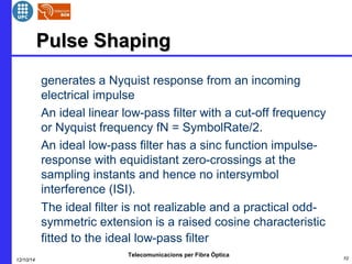
Optical filters are key components of optical communication
systems. They are widely used for WDM signal
demultiplexing, noise and distortion suppression, fiber
dispersion compensating
Filter characteristics can be defined completely by the
transfer function. Module and argument of the complex-valued
transfer function H(ω) describe the magnitude and
phase frequency responses of the filter on the input
harmonic signals E(t) = exp[j(ωt+φ0)]. If the filter transfer
function is known, then the filtered signal in the frequency
domain can be found simply as a product of the input signal
spectrum and the filter transfer function: Eout(ω) =
H(ω)Ein(ω).
Telecomunicacions per Fibra Òptica
12/10/14 15](https://image.slidesharecdn.com/ofdminopticals-141012092630-conversion-gate01/85/Ofdm-in-opticals-15-320.jpg)
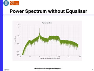
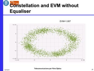
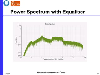
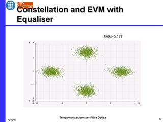

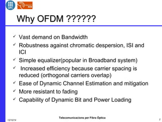
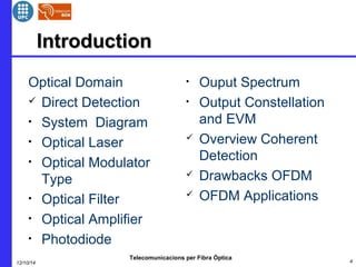
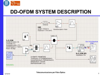
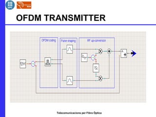
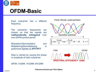
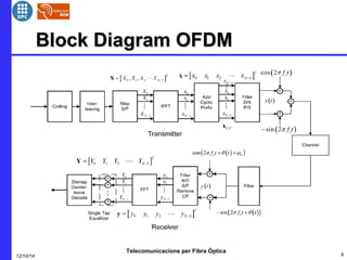
This document provides an overview of optical OFDM (orthogonal frequency-division multiplexing) systems. It discusses why OFDM is used, including its ability to mitigate chromatic dispersion and intersymbol interference. It then describes the basic principles of OFDM, including how data is divided into parallel streams and transmitted on separate subcarriers. It also outlines the key components of an optical OFDM system, such as lasers, modulators, filters, photodiodes, and how these components are used in an optical OFDM transmitter and receiver. It shows examples of output constellations and error vector magnitude with and without equalization components.