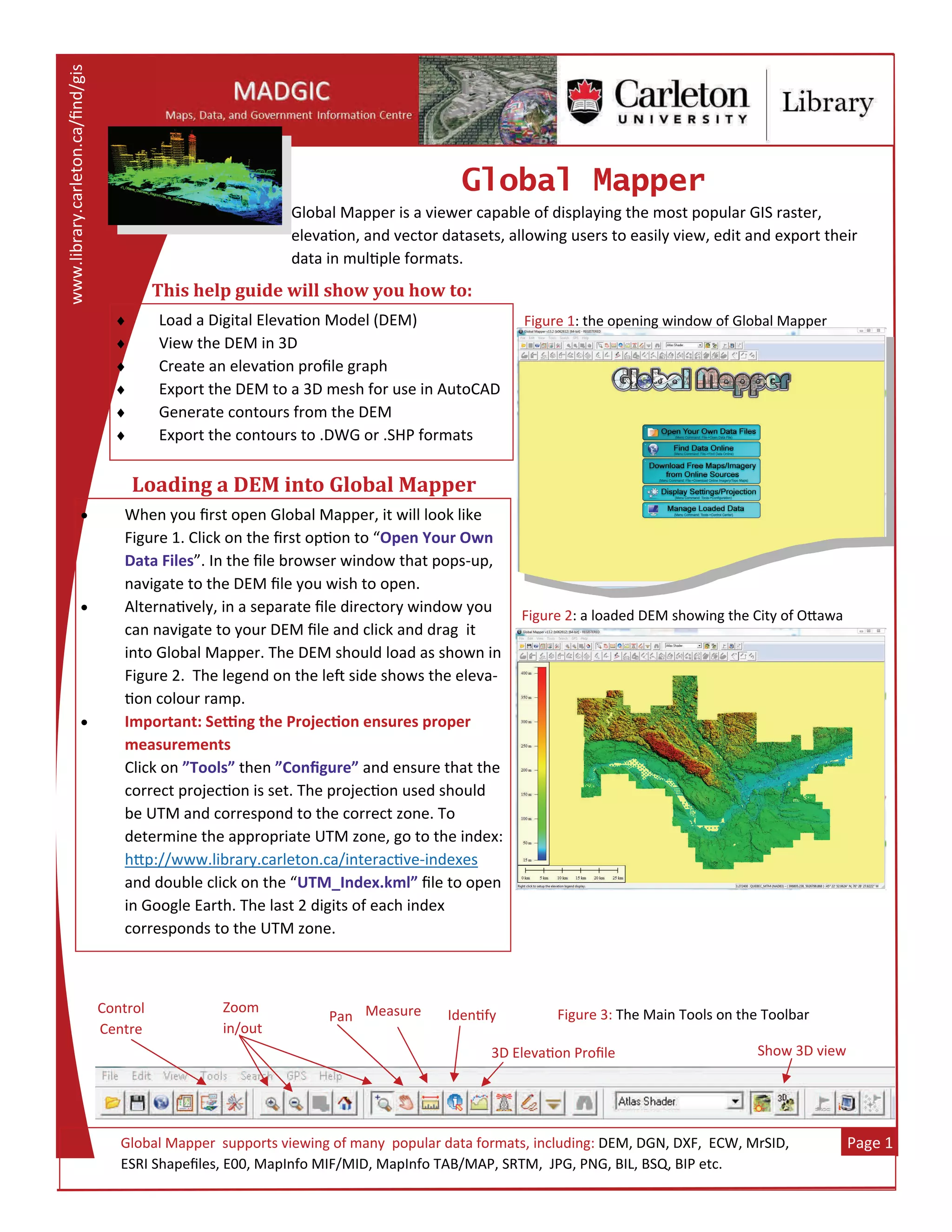
Global Mapper is a viewer capable of displaying the most popular GIS raster, 
eleva on, and vector datasets, allowing users to easily view, edit and export their 
data in mul ple formats. 
www.library.carleton.ca/find/gis 
Page 1 
Global Mapper
Loading	a	DEM	into	Global	Mapper	
 Load a Digital Eleva on Model (DEM) 
 View the DEM in 3D 
 Create an eleva on profile graph 
 Export the DEM to a 3D mesh for use in AutoCAD 
 Generate contours from the DEM 
 Export the contours to .DWG or .SHP formats 
 When you first open Global Mapper, it will look like 
Figure 1. Click on the first op on to “Open Your Own 
Data Files”. In the file browser window that pops‐up, 
navigate to the DEM file you wish to open.  
 Alterna vely, in a separate file directory window you 
can navigate to your DEM file and click and drag  it 
into Global Mapper. The DEM should load as shown in 
Figure 2.  The legend on the le  side shows the eleva‐
on colour ramp.  
 Important: Se ng the Projec on ensures proper 
measurements 
Click on ”Tools” then ”Configure” and ensure that the 
correct projec on is set. The projec on used should 
be UTM and correspond to the correct zone. To  
determine the appropriate UTM zone, go to the index: 
h p://www.library.carleton.ca/interac ve‐indexes 
and double click on the “UTM_Index.kml” file to open 
in Google Earth. The last 2 digits of each index  
corresponds to the UTM zone. 
Figure 1: the opening window of Global Mapper 
  Global Mapper  supports viewing of many  popular data formats, including: DEM, DGN, DXF,  ECW, MrSID,  
  ESRI Shapefiles, E00, MapInfo MIF/MID, MapInfo TAB/MAP, SRTM,  JPG, PNG, BIL, BSQ, BIP etc. 
Figure 2: a loaded DEM showing the City of O awa 
Control  
Centre 
Zoom  
in/out 
Measure Pan  Iden fy 
Show 3D view 3D Eleva on Profile 
Figure 3: The Main Tools on the Toolbar 
This	help	guide	will	show	you	how	to:
 
Page 2 
Global Mapper  Viewing	the	DEM	in	3D	
When viewing  files with an eleva on component, such as 
DEMs or LiDAR, you can click on the “Show 3D View” 
bu on (see Figure 3 on previous page).  This will open an 3D 
View window where you can pan, zoom, and rotate the 
view using the by clicking on the tool icons shown here:                             
Figure 6 (below): the eleva on profile graph showing changing 
eleva on over distance. 
Creating	an	Elevation	Pro ile	
An eleva on profile graph will show you the eleva on in a cross‐sec on of the DEM., as shown in Figure 6. To 
start, click on the  “3D Eleva on Profile” bu on (see figure 3 on previous page). This will  pop‐up a “Tip” box, 
to which you can just click “OK” to.  
 
With the cursor, click to draw a line across the DEM for which you are interested in seeing the eleva on pro‐
file for (Figure 5). Le ‐clicking will stop drawing your line and the eleva on path profile window will pop‐up.  
Figure 4 (le ): a 3D view of Ga neau Park from the O awa DEM. 
Exporting	a	DEM	to	a	3D	.DXF	Mesh	for	AutoCAD	
A 3D surface model for use in AutoCAD can be created by expor ng the DEM into a DXF mesh.  The first step is to 
roughly zoom into the area you are interested in expor ng. Try  not to take too much excess area, in order to speed up 
the drawing process of the mesh.  
 
     Once you’re zoomed into your area, click on “File”  then “Export Eleva on 
grid Format”.  This will pop‐up the “Select   
     Export Format” window (Figure 7). From the  drop‐down menu, select the 
“DXF  
      mesh”  file format; then click “OK”.   
 
    Con nued on next page….. Figure 7 : the Select Export Format pop‐up window 
Figure 5: the eleva on profile cross sec on line 
 
Page 3 
Global Mapper 
 Next, a “DXF Mesh Export Op ons” box will appear (Figure 8). You can change the pa‐
rameters to whatever suits your dataset, but remember to check ON the “Interpolate 
to Fill in Small Gaps in the Data”.   
 Secondly, click on the “Export bounds” tab, then the “Draw a Box” bu on to more spe‐
cifically select your area to export by drawing a box in the pop‐up window. Everything 
inside this box will be exported to your mesh. 
 Once you press Ok, a file browser window will pop‐up. Locate your output folder and 
give the mesh an appropriate name. The expor ng will begin...this may take some  me 
depending on the size of your area. 
Exporting	a	DEM	to	a	3D	.DXF	Mesh	for	AutoCAD	...continued	
Figure 8 (le ): the DXF Mesh Export 
Op ons (General) window.  
 
Figure 9 (right): the DXF Mesh 
 Export Op ons (Export Bounds) 
window.  
Once your mesh is done  
expor ng, open it in AutoCAD 
Map 3D. 
 
When it first opens, you will 
only see black or a grey grid. 
Click on the “3D” bu on to 
view the mesh properly in 3D, 
as seen in Figure 10. 
Figure 10 (le ): 
The 3D mesh  
surface shown in  
AutoCAD Map 3D Click on the “3D” bu on to ini ate this view. 
 
Page 4 
Global Mapper 
 Contours can be generated easily in Global Mapper by clicking on File, then Generate 
Contours...This will open the Contour Genera on Op ons window, as shown in Figure 
11.  The main thing you have to fill out is the Contour Interval; however, you can cus‐
tomize some of the other op ons as you see fit. The smaller the contour intervals, the 
longer it will take to generate.  
 Similarly, if you click on the Simplifica on tab, you will see a slider (Figure 12). To the 
le  creates smoother contours (i.e. less angular), but takes a bit more  me.  
 To select the area you wish to generate the contours for, click on the Contour Bounds 
tab and select the Draw a Box bu on. Press OK once you are done to start the contour 
genera on.  
Generating	Contours	
Figure 11: the Contour Op ons window    Figure 12: the Simplifica on tab  
Figure 13: the newly  
created contours.  
To export theses 
contours as vectors in 
SHP or DWG formats, 
select from the menu 
File then Export Vector  
Format…  

Global mapper

  • 1.
    Global Mapper is a viewer capable of displaying the most popular GIS raster,  eleva on, and vector datasets, allowing users to easily view, edit and export their  data in mul ple formats.  www.library.carleton.ca/find/gis  Page 1  GlobalMapper Loading a DEM into Global Mapper  Load a Digital Eleva on Model (DEM)   View the DEM in 3D   Create an eleva on profile graph   Export the DEM to a 3D mesh for use in AutoCAD   Generate contours from the DEM   Export the contours to .DWG or .SHP formats   When you first open Global Mapper, it will look like  Figure 1. Click on the first op on to “Open Your Own  Data Files”. In the file browser window that pops‐up,  navigate to the DEM file you wish to open.    Alterna vely, in a separate file directory window you  can navigate to your DEM file and click and drag  it  into Global Mapper. The DEM should load as shown in  Figure 2.  The legend on the le  side shows the eleva‐ on colour ramp.    Important: Se ng the Projec on ensures proper  measurements  Click on ”Tools” then ”Configure” and ensure that the  correct projec on is set. The projec on used should  be UTM and correspond to the correct zone. To   determine the appropriate UTM zone, go to the index:  h p://www.library.carleton.ca/interac ve‐indexes  and double click on the “UTM_Index.kml” file to open  in Google Earth. The last 2 digits of each index   corresponds to the UTM zone.  Figure 1: the opening window of Global Mapper    Global Mapper  supports viewing of many  popular data formats, including: DEM, DGN, DXF,  ECW, MrSID,     ESRI Shapefiles, E00, MapInfo MIF/MID, MapInfo TAB/MAP, SRTM,  JPG, PNG, BIL, BSQ, BIP etc.  Figure 2: a loaded DEM showing the City of O awa  Control   Centre  Zoom   in/out  Measure Pan  Iden fy  Show 3D view 3D Eleva on Profile  Figure 3: The Main Tools on the Toolbar  This help guide will show you how to:
  • 2.
      Page 2  Global Mapper  Viewing the DEM in 3D When viewing  files with an eleva on component, such as  DEMs or LiDAR, you can click on the “Show 3D View”  buon (see Figure 3 on previous page).  This will open an 3D  View window where you can pan, zoom, and rotate the  view using the by clicking on the tool icons shown here:                              Figure 6 (below): the eleva on profile graph showing changing  eleva on over distance.  Creating an Elevation Pro ile An eleva on profile graph will show you the eleva on in a cross‐sec on of the DEM., as shown in Figure 6. To  start, click on the  “3D Eleva on Profile” bu on (see figure 3 on previous page). This will  pop‐up a “Tip” box,  to which you can just click “OK” to.     With the cursor, click to draw a line across the DEM for which you are interested in seeing the eleva on pro‐ file for (Figure 5). Le ‐clicking will stop drawing your line and the eleva on path profile window will pop‐up.   Figure 4 (le ): a 3D view of Ga neau Park from the O awa DEM.  Exporting a DEM to a 3D .DXF Mesh for AutoCAD A 3D surface model for use in AutoCAD can be created by expor ng the DEM into a DXF mesh.  The first step is to  roughly zoom into the area you are interested in expor ng. Try  not to take too much excess area, in order to speed up  the drawing process of the mesh.          Once you’re zoomed into your area, click on “File”  then “Export Eleva on  grid Format”.  This will pop‐up the “Select         Export Format” window (Figure 7). From the  drop‐down menu, select the  “DXF         mesh”  file format; then click “OK”.          Con nued on next page….. Figure 7 : the Select Export Format pop‐up window  Figure 5: the eleva on profile cross sec on line 
  • 3.
      Page 3  Global Mapper   Next, a “DXF Mesh Export Op ons” box will appear (Figure 8). You can change the pa‐ rameters to whatever suits your dataset, but remember to check ON the “Interpolate  to Fill in Small Gaps in the Data”.    Secondly, click on the “Export bounds” tab, then the “Draw a Box” bu on to more spe‐ cifically select your area to export by drawing a box in the pop‐up window. Everything  inside this box will be exported to your mesh.   Once you press Ok, a file browser window will pop‐up. Locate your output folder and  give the mesh an appropriate name. The expor ng will begin...this may take some  me  depending on the size of your area.  Exporting a DEM to a 3D .DXF Mesh for AutoCAD ...continued Figure 8 (le ): the DXF Mesh Export  Op ons (General) window.     Figure 9 (right): the DXF Mesh   Export Op ons (Export Bounds)  window.   Once your mesh is done   expor ng, open it in AutoCAD  Map 3D.    When it first opens, you will  only see black or a grey grid.  Click on the “3D” bu on to  view the mesh properly in 3D,  as seen in Figure 10.  Figure 10 (le ):  The 3D mesh   surface shown in   AutoCAD Map 3D Click on the “3D” bu on to ini ate this view. 
  • 4.
      Page 4  Global Mapper   Contours can be generated easily in Global Mapper by clicking on File, then Generate  Contours...This will open the Contour Genera on Opons window, as shown in Figure  11.  The main thing you have to fill out is the Contour Interval; however, you can cus‐ tomize some of the other op ons as you see fit. The smaller the contour intervals, the  longer it will take to generate.    Similarly, if you click on the Simplifica on tab, you will see a slider (Figure 12). To the  le  creates smoother contours (i.e. less angular), but takes a bit more  me.    To select the area you wish to generate the contours for, click on the Contour Bounds  tab and select the Draw a Box bu on. Press OK once you are done to start the contour  genera on.   Generating Contours Figure 11: the Contour Op ons window    Figure 12: the Simplifica on tab   Figure 13: the newly   created contours.   To export theses  contours as vectors in  SHP or DWG formats,  select from the menu  File then Export Vector   Format…