Downloaded 297 times


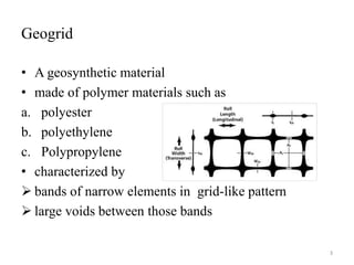
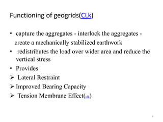
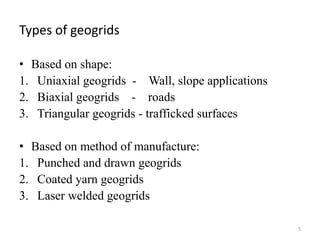
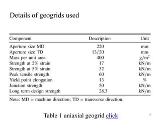
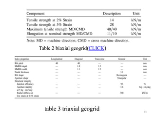
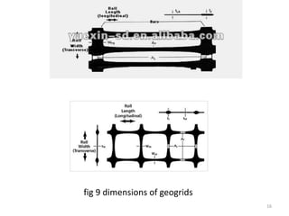

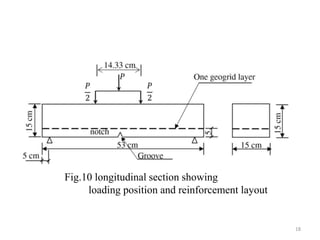
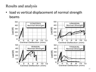
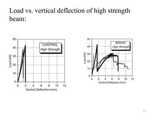
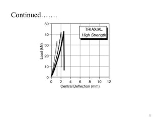
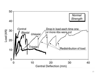
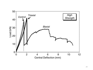
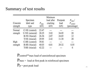
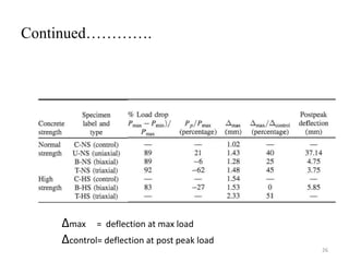


1) The document discusses the use of geogrid reinforcement in concrete. Geogrids are made of polymer materials and have a grid-like pattern that can interlock with aggregates to improve the properties of concrete. 2) A series of flexural tests were conducted on concrete beams with and without different types of geogrid reinforcement. The results showed that geogrid reinforcement increased the load capacity, deflection, and fracture energy of the beams compared to unreinforced beams. 3) Uniaxial geogrids provided the highest increase in ductility and energy absorption but triaxial geogrids performed best as a whole reinforcement. The type of geogrid and its properties influenced the


