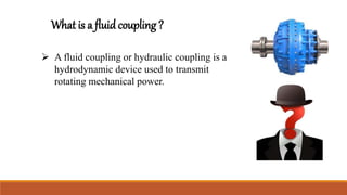
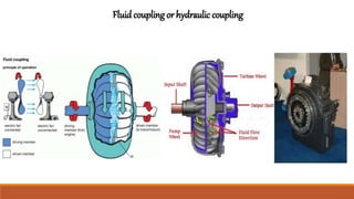
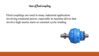
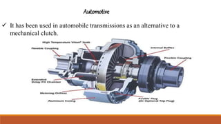
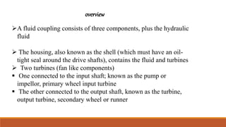
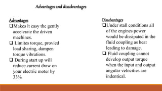
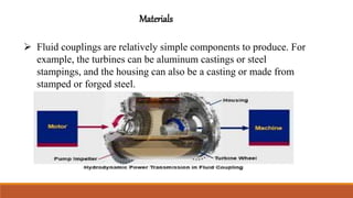
Fluid coupling
prepared By
Muhammad AslamBaig cecos university
Cu-440-2016 peshawar
ME-2017 MED
 Hydraulic coupling
 Video of hydraulic coupling
 Overview
 Materials
 Application
What is a fluid coupling ?
 A fluid coupling or hydraulic coupling is a
hydrodynamic device used to transmit
rotating mechanical power.
History of fluidcoupling
 The fluid coupling originates from the work of Dr.
Hermann Föttinger, who was the chief designer at
the AG Vulcan Works in Stettin.
 Hermann Föttinger (born 9 February 1877 in
Nuremberg; died 28 April 1945 in Berlin) was a
German engineer and inventor
Dr. Hermann Fottinger
Fluid coupling or hydraulic coupling
 Function
 it is used for transmitting power or torque from one shaft to
other shaft with help of an oil (fluid) without Mechanical
connection between the two shafts
 Construction
 It consist of two rotating elements as radial pump impeller and radial
flow reaction. The pump impeller is mounted on a driving shaft and
turbine runner is mounted on a driven shaft. Both the impeller and the
runner are identical in shape and they are enclosed in a single housing
filled with fluid (oil). The function of oil is to transmit torque from pump
impeller to the turbine runner and also provide lubrication, and stability.
There is no direct contact between the driving and driven parts.
 Working
 When the driving shaft with pump impeller is rotated, the oil start moving from
the inner radius to the outer radius of the pump impeller by centrifugal action.
Due to centrifugal action and speed of the pump impeller, the pressure and
kinetic energy of oil at the outer radius increases. This oil then enters the
turbine runner at the outer radius of the runner & flows inwardly to the inner
radius of runner. The oil, while flowing through the turbine runner exerts force
on the runner blades & makes the runner to rotate. The magnitude of the torque
increases with an increase in the speed of the driving shaft. The oil from the
runner then flows back into the pump impeller, hence having a continuous
circulation. In the actual practice, the speed of the driven shaft is always less
than the driving shaft by 2% - 4% due to friction & turbulence loss in the
impeller and runner passage, which is known as slip
Uses of fluid coupling
Fluid couplings are used in many industrial application
involving rotational power, especially in machine drives that
involve high inertia starts or constant cyclic loading
Automotive
 It has been used in automobile transmissions as an alternative to a
mechanical clutch.
Efficiency is 98%
overview
A fluid coupling consists of three components, plus the hydraulic
fluid
 The housing, also known as the shell (which must have an oil-
tight seal around the drive shafts), contains the fluid and turbines
 Two turbines (fan like components)
 One connected to the input shaft; known as the pump or
impellor, primary wheel input turbine
 The other connected to the output shaft, known as the turbine,
output turbine, secondary wheel or runner
Advantages
Makes it easy the gently
accelerate the driven
machines.
 Limites torque, provied
load sharing, dampen
torque vibrations.
 During start up will
reduce current draw on
your electric moter by
33%
Disadvantages
Under stall conditions all
of the engines power
would be dissipated in the
fluid coupling as heat
leading to damage.
 Fluid coupling cannot
develop output torque
when the input and output
angular velocities are
indentical.
Advantages and disadvantages
Materials
 Fluid couplings are relatively simple components to produce. For
example, the turbines can be aluminum castings or steel
stampings, and the housing can also be a casting or made from
stamped or forged steel.
Application
 Industrial
The fluid coupling is generally used where soft start and variable loading or variable speed required.
These kinds of applications are generally works in power plants, refineries, coal mines.
Power plant
In power plant there is various equipment which requires fluid coupling some of are as follows
1) Fans Fans are the important equipment of the power plant, it required to operate at variable speed for
variable power generation. Hence for the variable speed the fluid coupling is needed for the SA, PA, ID
FD and other fans.
2) 2) Pumps Boiler is the important part of the power plant and it operates at very high pressure. For
feeding of fresh water into the boiler high pressure pumps required and these high pressure pumps
required very high torque for starting. Hence fluid coupling employed into them.
3) Mines The fluid coupling used in conveyors in mines for moving raw material from mining point to
transportation point.
4) Refineries: The petroleum fluid has high viscosity and the viscosity of the petroleum fluid varies with the
temperature. For transportation of petroleum special pumps required which can work with varies density of the
fluid. So that the power and speed of the pump varies. So that fluid coupling employed for the varies power
requirement.
5) Pulp industries: The pulp industries have to handle the slurry, the slurry has not the same density
homogeneously and the pump which handles this slurry varies speed. For this variable speed and power
requirement fluid coupling is useful for the application.
6) Automotive: The fluid coupling can work as a clutch in an automobile. Fluid coupling also used in heavy
vehicle like trucks as a retarder unit.
7) Railways: in a railway locomotive the fluid coupling used in power transmission train for varying load and
high torque required to pull the train.
8) Aviation: The most prominent use of fluid couplings in aeronautical applications was in the Wright turbo
compound reciprocating engine, in which three power recovery turbines extracted approximately 20 percent of
the energy or about 500 horsepower (370 kW) from the engine's exhaust gases and then, using three fluid
couplings and gearing, converted low-torque high-speed turbine rotation to low-speed, high-torque output to
drive the propeller
Fluid coupling with complete study resources

Fluid coupling with complete study resources

  • 1.
    Fluid coupling prepared By MuhammadAslamBaig cecos university Cu-440-2016 peshawar ME-2017 MED
  • 2.
     Hydraulic coupling Video of hydraulic coupling  Overview  Materials  Application
  • 3.
    What is afluid coupling ?  A fluid coupling or hydraulic coupling is a hydrodynamic device used to transmit rotating mechanical power.
  • 4.
    History of fluidcoupling The fluid coupling originates from the work of Dr. Hermann Föttinger, who was the chief designer at the AG Vulcan Works in Stettin.  Hermann Föttinger (born 9 February 1877 in Nuremberg; died 28 April 1945 in Berlin) was a German engineer and inventor Dr. Hermann Fottinger
  • 5.
    Fluid coupling orhydraulic coupling
  • 6.
     Function  itis used for transmitting power or torque from one shaft to other shaft with help of an oil (fluid) without Mechanical connection between the two shafts  Construction  It consist of two rotating elements as radial pump impeller and radial flow reaction. The pump impeller is mounted on a driving shaft and turbine runner is mounted on a driven shaft. Both the impeller and the runner are identical in shape and they are enclosed in a single housing filled with fluid (oil). The function of oil is to transmit torque from pump impeller to the turbine runner and also provide lubrication, and stability. There is no direct contact between the driving and driven parts.
  • 7.
     Working  Whenthe driving shaft with pump impeller is rotated, the oil start moving from the inner radius to the outer radius of the pump impeller by centrifugal action. Due to centrifugal action and speed of the pump impeller, the pressure and kinetic energy of oil at the outer radius increases. This oil then enters the turbine runner at the outer radius of the runner & flows inwardly to the inner radius of runner. The oil, while flowing through the turbine runner exerts force on the runner blades & makes the runner to rotate. The magnitude of the torque increases with an increase in the speed of the driving shaft. The oil from the runner then flows back into the pump impeller, hence having a continuous circulation. In the actual practice, the speed of the driven shaft is always less than the driving shaft by 2% - 4% due to friction & turbulence loss in the impeller and runner passage, which is known as slip
  • 8.
    Uses of fluidcoupling Fluid couplings are used in many industrial application involving rotational power, especially in machine drives that involve high inertia starts or constant cyclic loading
  • 9.
    Automotive  It hasbeen used in automobile transmissions as an alternative to a mechanical clutch.
  • 10.
  • 11.
    overview A fluid couplingconsists of three components, plus the hydraulic fluid  The housing, also known as the shell (which must have an oil- tight seal around the drive shafts), contains the fluid and turbines  Two turbines (fan like components)  One connected to the input shaft; known as the pump or impellor, primary wheel input turbine  The other connected to the output shaft, known as the turbine, output turbine, secondary wheel or runner
  • 12.
    Advantages Makes it easythe gently accelerate the driven machines.  Limites torque, provied load sharing, dampen torque vibrations.  During start up will reduce current draw on your electric moter by 33% Disadvantages Under stall conditions all of the engines power would be dissipated in the fluid coupling as heat leading to damage.  Fluid coupling cannot develop output torque when the input and output angular velocities are indentical. Advantages and disadvantages
  • 13.
    Materials  Fluid couplingsare relatively simple components to produce. For example, the turbines can be aluminum castings or steel stampings, and the housing can also be a casting or made from stamped or forged steel.
  • 14.
    Application  Industrial The fluidcoupling is generally used where soft start and variable loading or variable speed required. These kinds of applications are generally works in power plants, refineries, coal mines. Power plant In power plant there is various equipment which requires fluid coupling some of are as follows 1) Fans Fans are the important equipment of the power plant, it required to operate at variable speed for variable power generation. Hence for the variable speed the fluid coupling is needed for the SA, PA, ID FD and other fans. 2) 2) Pumps Boiler is the important part of the power plant and it operates at very high pressure. For feeding of fresh water into the boiler high pressure pumps required and these high pressure pumps required very high torque for starting. Hence fluid coupling employed into them. 3) Mines The fluid coupling used in conveyors in mines for moving raw material from mining point to transportation point.
  • 15.
    4) Refineries: Thepetroleum fluid has high viscosity and the viscosity of the petroleum fluid varies with the temperature. For transportation of petroleum special pumps required which can work with varies density of the fluid. So that the power and speed of the pump varies. So that fluid coupling employed for the varies power requirement. 5) Pulp industries: The pulp industries have to handle the slurry, the slurry has not the same density homogeneously and the pump which handles this slurry varies speed. For this variable speed and power requirement fluid coupling is useful for the application. 6) Automotive: The fluid coupling can work as a clutch in an automobile. Fluid coupling also used in heavy vehicle like trucks as a retarder unit. 7) Railways: in a railway locomotive the fluid coupling used in power transmission train for varying load and high torque required to pull the train. 8) Aviation: The most prominent use of fluid couplings in aeronautical applications was in the Wright turbo compound reciprocating engine, in which three power recovery turbines extracted approximately 20 percent of the energy or about 500 horsepower (370 kW) from the engine's exhaust gases and then, using three fluid couplings and gearing, converted low-torque high-speed turbine rotation to low-speed, high-torque output to drive the propeller