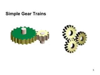
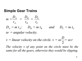
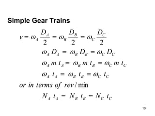
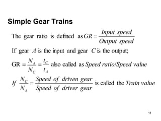
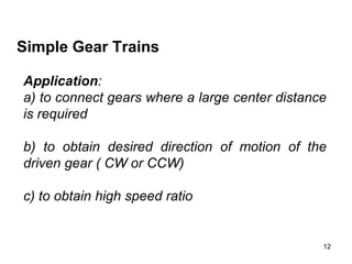
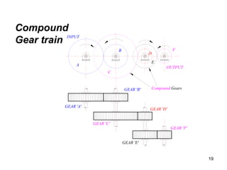
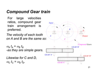
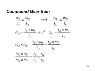
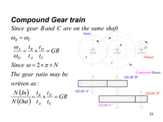
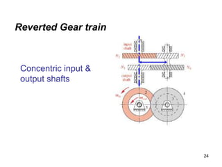
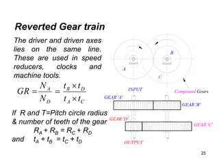
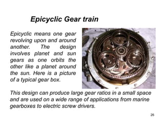
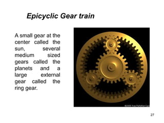
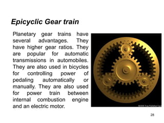
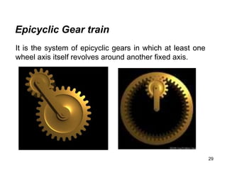
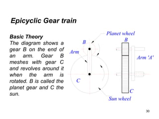
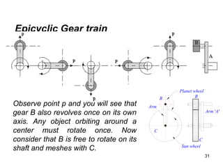
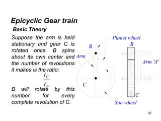
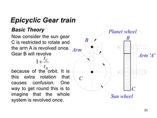
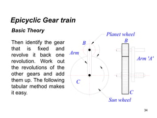
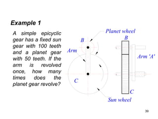
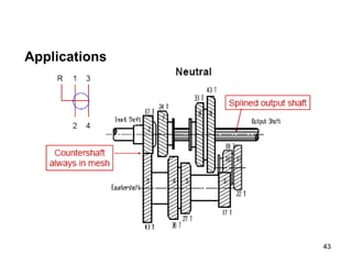
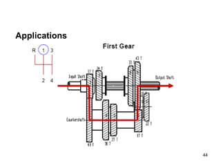
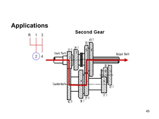
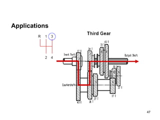
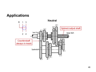
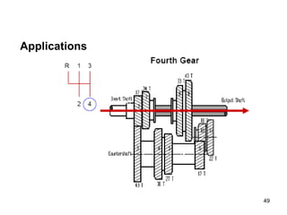
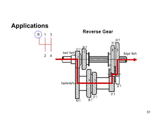
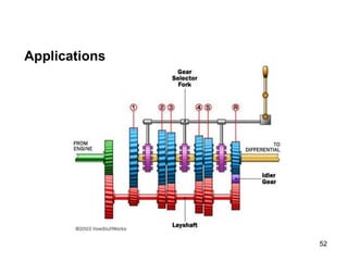
Unit -4
Gears and Geartrains
1
2
Interference in involute Gears
Methods to avoid Interference
Minimum number of teeth on the pinion avoid
Interference
Minimum number of teeth on the wheel avoid
Interference
Minimum number of teeth on the pinion for involute
rack to avoid Interference Backlash
3
Gear Trains
A gear train is two or more gear working together by
meshing their teeth and turning each other in a system to
generate power and speed. It reduces speed and
increases torque. To create large gear ratio, gears are
connected together to form gear trains. They often
consist of multiple gears in the train.
The most common of the gear train is the gear pair
connecting parallel shafts. The teeth of this type can be
spur, helical or herringbone. The angular velocity is
simply the reverse of the tooth ratio.
4
Gear Trains
Any combination of gear
wheels employed to transmit
motion from one shaft to the
other is called a gear train.
The meshing of two gears
may be idealized as two
smooth discs with their
edges touching and no slip
between them. This ideal
diameter is called the Pitch
Circle Diameter (PCD) of the
gear.
5
Simple Gear Trains
6
C
Simple Gear Trains
(Idler gear)
GEAR 'C'
GEAR 'B'
GEAR 'A'
v
v
C

B

A

The typical spur
gears as shown in
diagram. The
direction of rotation
is reversed from
one gear to
another.
The only function
of the idler gear is
to change the
direction of rotation.
7
(Idler gear)
GEAR 'C'
GEAR 'B'
GEAR 'A'
v
v
C

B

A

Simple Gear Trains
It has no affect on
the gear ratio. The
teeth on the gears
must all be the same
size so if gear A
advances one tooth,
so does B and C.
8
C
Simple Gear Trains
.
module
module
mesh
would not
rwise they
gears othe
all
e same for
must be th
and
t
D
=
m =
in rpm
N = speed
meter,
circle dia
D = Pitch
r,
on the gea
of teeth
t = number
9
Simple Gear Trains
r
=
D
cle. v =
on the cir
velocity
v = linear
.
r velocity
= angula
= m t
D
and
= m t
D
;
= m t
D
t
D
=
t
D
=
t
D
m =
C
C
B
B
A
A
C
C
B
B
A
A



2
The velocity v of any point on the circle must be the
same for all the gears, otherwise they would be slipping.
10
Simple Gear Trains
C
C
B
B
A
A
C
C
B
B
A
A
C
C
B
B
A
A
C
C
B
B
A
A
C
C
B
B
A
A
t
N
t
N
t
N
rev
of
terms
in
or
t
t
t
t
m
t
m
t
m
D
D
D
D
D
D
v











min
/
2
2
2












11
Simple Gear Trains
value
Train
gear
driver
of
Speed
gear
driven
of
Speed
N
N
If
e
Speed valu
o
Speed rati
t
t
N
N
C
A
speed
Output
speed
Input
GR
A
C
A
C
C
A
the
called
is
/
as
called
also
GR
output;
the
is
gear
and
input
the
is
gear
If
as
defined
is
ratio
gear
The




12
Simple Gear Trains
Application:
a) to connect gears where a large center distance
is required
b) to obtain desired direction of motion of the
driven gear ( CW or CCW)
c) to obtain high speed ratio
13
Torque & Efficiency
The power transmitted by a torque T N-m applied to a
shaft rotating at N rev/min is given by:
60
2 T
N
P


In an ideal gear box, the input and output powers are the
same so;
GR
N
N
T
T
T
N
T
N
T
N
T
N
P






2
1
1
2
2
2
1
1
2
2
1
1
60
2
60
2 

14
C
Torque & Efficiency
It follows that if the speed is reduced, the torque is
increased and vice versa. In a real gear box, power is lost
through friction and the power output is smaller than the
power input. The efficiency is defined as:
1
1
2
2
1
1
2
2
60
2
60
2
T
N
T
N
T
N
T
N
In
Power
out
Power










Because the torque in and out is different, a gear box has
to be clamped in order to stop the case or body rotating.
A holding torque T3 must be applied to the body through
the clamps.
15
Torque & Efficiency
The total torque must add up to
zero.
T1 + T2 + T3 = 0
If we use a convention that anti-
clockwise is positive and
clockwise is negative we can
determine the holding torque.
The direction of rotation of the
output shaft depends on the
design of the gear box.
16
Problem 1
A gear box has an input speed of 1500 rev/min clockwise
and an output speed of 300 rev/min anticlockwise. The input
power is 20 kW and the efficiency is 70%. Determine the
following.
i. The gear ratio; ii. The input torque.; iii. The output
power.; iv. The output torque; v. The holding torque.
1
1
1
1
2
1
2
60
60
2
5
300
1500
.
:
N
Power
Input
T
T
N
Power
Input
N
N
speed
Output
speed
Input
VR
or
R
G
Solution












17
Problem 1
)
(
3
.
127
1500
2
20000
60
1
clockwise
Negative
m
N
T
torque
Input








kW
Output
Power
power
Inpu
power
Output
14
20
7
.
0
7
.
0






 
ise
unticlockw
Positive
m
N
T
torque
Output






 6
.
445
300
2
14000
60
2

18
Problem 1
Clockwise
m
N
T
T
T
T
T













3
.
318
6
.
445
3
.
127
0
6
.
445
3
.
127
0
3
3
3
2
1
19
GEAR 'A'
GEAR 'B'
GEAR 'C'
GEAR 'D'
GEAR 'F'
GEAR 'E'
Compound Gears
A
C
B
E
D
F
OUTPUT
INPUT
Compound
Gear train
20
Compound Gear train
GEAR 'A'
GEAR 'B'
GEAR 'C'
GEAR 'D'
Compound Gears
A
C
B
D
Output
Input
Compound gears are
simply a chain of simple
gear trains with the input of
the second being the
output of the first. A chain
of two pairs is shown
below. Gear B is the output
of the first pair and gear C
is the input of the second
pair. Gears B and C are
locked to the same shaft
and revolve at the same
speed.
21
Compound Gear train
GEAR 'A'
GEAR 'B'
GEAR 'C'
GEAR 'D'
Compound Gears
A
C
B
D
Output
Input
The velocity of each tooth
on A and B are the same so:
A tA = B tB
-as they are simple gears.
Likewise for C and D,
C tC = D tD.
For large velocities
ratios, compound gear
train arrangement is
preferred.
22
Compound Gear train
C
D
A
B
D
B
C
A
C
D
D
A
B
B
C
A
C
D
D
C
A
B
B
A
C
D
D
C
A
B
B
A
t
t
t
t
t
t
t
t
T
t
and
t
t
t
t
and
t
t































23
Compound Gear train
GEAR 'A'
GEAR 'B'
GEAR 'C'
GEAR 'D'
Compound Gears
A
C
B
D
Output
Input
 
 
GR
t
t
t
t
Out
N
In
N
as
written
be
may
ratio
gear
The
N
Since
GR
t
t
t
t
shaft
same
the
on
are
C
and
B
gear
Since
C
D
A
B
C
D
A
B
D
A
C
B










:
2 





24
Reverted Gear train
Concentric input &
output shafts
25
GEAR 'B'
GEAR 'C'
Compound Gears
A
C
B
INPUT
OUTPUT
GEAR 'A'
GEAR 'D'
The driver and driven axes
lies on the same line.
These are used in speed
reducers, clocks and
machine tools.
C
A
D
B
D
A
t
t
t
t
N
N
GR




If R and T=Pitch circle radius
& number of teeth of the gear
RA + RB = RC + RD
and tA + tB = tC + tD
Reverted Gear train
26
Epicyclic means one gear
revolving upon and around
another. The design
involves planet and sun
gears as one orbits the
other like a planet around
the sun. Here is a picture
of a typical gear box.
Epicyclic Gear train
This design can produce large gear ratios in a small space
and are used on a wide range of applications from marine
gearboxes to electric screw drivers.
27
A small gear at the
center called the
sun, several
medium sized
gears called the
planets and a
large external
gear called the
ring gear.
Epicyclic Gear train
28
Epicyclic Gear train
Planetary gear trains have
several advantages. They
have higher gear ratios. They
are popular for automatic
transmissions in automobiles.
They are also used in bicycles
for controlling power of
pedaling automatically or
manually. They are also used
for power train between
internal combustion engine
and an electric motor.
29
Epicyclic Gear train
It is the system of epicyclic gears in which at least one
wheel axis itself revolves around another fixed axis.
30
Epicyclic Gear train
Arm 'A'
B
C
Planet wheel
Sun wheel
Arm
B
C
Basic Theory
The diagram shows a
gear B on the end of
an arm. Gear B
meshes with gear C
and revolves around it
when the arm is
rotated. B is called the
planet gear and C the
sun.
31
Epicyclic Gear train
Basic Theory
Arm 'A'
B
C
Planet wheel
Sun wheel
Arm
B
C
Observe point p and you will see that
gear B also revolves once on its own
axis. Any object orbiting around a
center must rotate once. Now
consider that B is free to rotate on its
shaft and meshes with C.
32
Epicyclic Gear train
Arm 'A'
B
C
Planet wheel
Sun wheel
Arm
B
C
Suppose the arm is held
stationary and gear C is
rotated once. B spins
about its own center and
the number of revolutions
it makes is the ratio:
B will rotate by this
number for every
complete revolution of C.
B
C
t
t
Basic Theory
33
Epicyclic Gear train
Arm 'A'
B
C
Planet wheel
Sun wheel
Arm
B
C
Basic Theory
Now consider the sun gear
C is restricted to rotate and
the arm A is revolved once.
Gear B will revolve
because of the orbit. It is
this extra rotation that
causes confusion. One
way to get round this is to
imagine that the whole
system is revolved once.
B
C
t
t

1
34
Epicyclic Gear train
Arm 'A'
B
C
Planet wheel
Sun wheel
Arm
B
C
Basic Theory
Then identify the gear
that is fixed and
revolve it back one
revolution. Work out
the revolutions of the
other gears and add
them up. The following
tabular method makes
it easy.
35
Epicyclic Gear train
Basic Theory
Suppose gear C is fixed and the arm A makes one
revolution. Determine how many revolutions the planet
gear B makes.
Step 1: revolve all elements once about the center.
Step 2: identify that C should be fixed and rotate it
backwards one revolution keeping the arm fixed as it
should only do one revolution in total. Work out the
revolutions of B.
Step 3: add them up and we find the total revolutions of
C is zero and for the arm is 1.
36
Epicyclic Gear train
Basic Theory
Step Action A B C
1 Revolve all once 1 1 1
2
3
37
Epicyclic Gear train
Basic Theory
B
C
t
t

Step Action A B C
1 Revolve all once 1 1 1
2
Revolve C by –1
revolution, keeping the
arm fixed
0 -1
3
38
Epicyclic Gear train
Basic Theory
B
C
t
t

B
C
t
t

1
Step Action A B C
1 Revolve all once 1 1 1
2
Revolve C by –1
revolution, keeping the
arm fixed
0 -1
3 Add 1 0
39
Arm 'A'
B
C
Planet wheel
Sun wheel
Arm
B
C
A simple epicyclic
gear has a fixed sun
gear with 100 teeth
and a planet gear
with 50 teeth. If the
arm is revolved
once, how many
times does the
planet gear revolve?
Example 1
40
Example 1-continued
Step Action A B C
1 Revolve all once 1 1 1
2
3
41
Example 1-continued
Step Action A B C
1 Revolve all once 1 1 1
2
Revolve C by –1
revolution, keeping
the arm fixed
0 -1
3
50
100

42
Example 1-continued
Step Action A B C
1 Revolve all once 1 1 1
2
Revolve C by –1
revolution, keeping
the arm fixed
0 -1
3 Add 1 3 0
50
100

43
Applications
44
Applications
45
Applications
46
Applications
47
Applications
48
Applications
49
Applications
50
Applications
51
Applications
52
Applications
53
Applications
Automotive Gears: Gears play an important role in
trucks, car, buses, motor bikes and even geared cycles.
These gears control speed and include gears like ring and
pinion, spiral gear, hypoid gear, hydraulic gears, reduction
gearbox.
54
Applications
Depending on the size of
the vehicles, the size of
the gears also varies.
There are low gears
covering a shorter
distance and are useful
when speed is low. There
are high gears also with
larger number of teeth.
55
Applications
56
Applications
Conveyor Systems:
Conveyor is a mechanical
apparatus for carrying bulk
material from place to
place at a controlled rate;
for example an endless
moving belt or a chain of
receptacles. There are
various types of conveyors
that are used for different
material handling needs.
57
Applications
Agro Industry: All agro machinery consists of different
types of gears depending upon their function and
property. Different gears are used differently in the
industry.
Wind Turbine: When the rotor rotates, the load on the
main shaft is very heavy. It runs with approximate 22
revolutions per minute but generator has to go a lot
faster. It cannot use the turning force to increase the
number of revolutions and that is why wind turbine uses
gear to increase the speed.
58
Applications
Power Station:
Helical gears - Are used to
minimise noise and power losses.
Bevel gears - Used to change the
axis of rotational motion.
Spur gears - Passes power from
idler gears to the wheels.
Planetary gears - Used between
internal combustion engine and an
electric motor to transmit power.
59
Applications
Marine Gears: Marine gears meet
a wide variety of marine
applications in a variety of
configurations and installations to
meet the most critical applications.
Specific marine applications
include main propulsion,
centrifuges, deck machinery such
as winches, windlasses, cranes,
turning gears, pumps, elevators,
and rudder carriers.
60
Applications
Mining Gears: Mining is a process
of extracting ores or minerals from
the earth's surface. The gears are
used for increasing the torque
applied on the tool used for mining.
They are used for commercial gold
production, and coal mining.
61
Differential Gear Box

Unit 4- Gear and Gear Trains.ppt

  • 1.
    Unit -4 Gears andGeartrains 1
  • 2.
    2 Interference in involuteGears Methods to avoid Interference Minimum number of teeth on the pinion avoid Interference Minimum number of teeth on the wheel avoid Interference Minimum number of teeth on the pinion for involute rack to avoid Interference Backlash
  • 3.
    3 Gear Trains A geartrain is two or more gear working together by meshing their teeth and turning each other in a system to generate power and speed. It reduces speed and increases torque. To create large gear ratio, gears are connected together to form gear trains. They often consist of multiple gears in the train. The most common of the gear train is the gear pair connecting parallel shafts. The teeth of this type can be spur, helical or herringbone. The angular velocity is simply the reverse of the tooth ratio.
  • 4.
    4 Gear Trains Any combinationof gear wheels employed to transmit motion from one shaft to the other is called a gear train. The meshing of two gears may be idealized as two smooth discs with their edges touching and no slip between them. This ideal diameter is called the Pitch Circle Diameter (PCD) of the gear.
  • 5.
  • 6.
    6 C Simple Gear Trains (Idlergear) GEAR 'C' GEAR 'B' GEAR 'A' v v C  B  A  The typical spur gears as shown in diagram. The direction of rotation is reversed from one gear to another. The only function of the idler gear is to change the direction of rotation.
  • 7.
    7 (Idler gear) GEAR 'C' GEAR'B' GEAR 'A' v v C  B  A  Simple Gear Trains It has no affect on the gear ratio. The teeth on the gears must all be the same size so if gear A advances one tooth, so does B and C.
  • 8.
    8 C Simple Gear Trains . module module mesh wouldnot rwise they gears othe all e same for must be th and t D = m = in rpm N = speed meter, circle dia D = Pitch r, on the gea of teeth t = number
  • 9.
    9 Simple Gear Trains r = D cle.v = on the cir velocity v = linear . r velocity = angula = m t D and = m t D ; = m t D t D = t D = t D m = C C B B A A C C B B A A    2 The velocity v of any point on the circle must be the same for all the gears, otherwise they would be slipping.
  • 10.
  • 11.
    11 Simple Gear Trains value Train gear driver of Speed gear driven of Speed N N If e Speedvalu o Speed rati t t N N C A speed Output speed Input GR A C A C C A the called is / as called also GR output; the is gear and input the is gear If as defined is ratio gear The    
  • 12.
    12 Simple Gear Trains Application: a)to connect gears where a large center distance is required b) to obtain desired direction of motion of the driven gear ( CW or CCW) c) to obtain high speed ratio
  • 13.
    13 Torque & Efficiency Thepower transmitted by a torque T N-m applied to a shaft rotating at N rev/min is given by: 60 2 T N P   In an ideal gear box, the input and output powers are the same so; GR N N T T T N T N T N T N P       2 1 1 2 2 2 1 1 2 2 1 1 60 2 60 2  
  • 14.
    14 C Torque & Efficiency Itfollows that if the speed is reduced, the torque is increased and vice versa. In a real gear box, power is lost through friction and the power output is smaller than the power input. The efficiency is defined as: 1 1 2 2 1 1 2 2 60 2 60 2 T N T N T N T N In Power out Power           Because the torque in and out is different, a gear box has to be clamped in order to stop the case or body rotating. A holding torque T3 must be applied to the body through the clamps.
  • 15.
    15 Torque & Efficiency Thetotal torque must add up to zero. T1 + T2 + T3 = 0 If we use a convention that anti- clockwise is positive and clockwise is negative we can determine the holding torque. The direction of rotation of the output shaft depends on the design of the gear box.
  • 16.
    16 Problem 1 A gearbox has an input speed of 1500 rev/min clockwise and an output speed of 300 rev/min anticlockwise. The input power is 20 kW and the efficiency is 70%. Determine the following. i. The gear ratio; ii. The input torque.; iii. The output power.; iv. The output torque; v. The holding torque. 1 1 1 1 2 1 2 60 60 2 5 300 1500 . : N Power Input T T N Power Input N N speed Output speed Input VR or R G Solution            
  • 17.
  • 18.
  • 19.
    19 GEAR 'A' GEAR 'B' GEAR'C' GEAR 'D' GEAR 'F' GEAR 'E' Compound Gears A C B E D F OUTPUT INPUT Compound Gear train
  • 20.
    20 Compound Gear train GEAR'A' GEAR 'B' GEAR 'C' GEAR 'D' Compound Gears A C B D Output Input Compound gears are simply a chain of simple gear trains with the input of the second being the output of the first. A chain of two pairs is shown below. Gear B is the output of the first pair and gear C is the input of the second pair. Gears B and C are locked to the same shaft and revolve at the same speed.
  • 21.
    21 Compound Gear train GEAR'A' GEAR 'B' GEAR 'C' GEAR 'D' Compound Gears A C B D Output Input The velocity of each tooth on A and B are the same so: A tA = B tB -as they are simple gears. Likewise for C and D, C tC = D tD. For large velocities ratios, compound gear train arrangement is preferred.
  • 22.
  • 23.
    23 Compound Gear train GEAR'A' GEAR 'B' GEAR 'C' GEAR 'D' Compound Gears A C B D Output Input     GR t t t t Out N In N as written be may ratio gear The N Since GR t t t t shaft same the on are C and B gear Since C D A B C D A B D A C B           : 2      
  • 24.
    24 Reverted Gear train Concentricinput & output shafts
  • 25.
    25 GEAR 'B' GEAR 'C' CompoundGears A C B INPUT OUTPUT GEAR 'A' GEAR 'D' The driver and driven axes lies on the same line. These are used in speed reducers, clocks and machine tools. C A D B D A t t t t N N GR     If R and T=Pitch circle radius & number of teeth of the gear RA + RB = RC + RD and tA + tB = tC + tD Reverted Gear train
  • 26.
    26 Epicyclic means onegear revolving upon and around another. The design involves planet and sun gears as one orbits the other like a planet around the sun. Here is a picture of a typical gear box. Epicyclic Gear train This design can produce large gear ratios in a small space and are used on a wide range of applications from marine gearboxes to electric screw drivers.
  • 27.
    27 A small gearat the center called the sun, several medium sized gears called the planets and a large external gear called the ring gear. Epicyclic Gear train
  • 28.
    28 Epicyclic Gear train Planetarygear trains have several advantages. They have higher gear ratios. They are popular for automatic transmissions in automobiles. They are also used in bicycles for controlling power of pedaling automatically or manually. They are also used for power train between internal combustion engine and an electric motor.
  • 29.
    29 Epicyclic Gear train Itis the system of epicyclic gears in which at least one wheel axis itself revolves around another fixed axis.
  • 30.
    30 Epicyclic Gear train Arm'A' B C Planet wheel Sun wheel Arm B C Basic Theory The diagram shows a gear B on the end of an arm. Gear B meshes with gear C and revolves around it when the arm is rotated. B is called the planet gear and C the sun.
  • 31.
    31 Epicyclic Gear train BasicTheory Arm 'A' B C Planet wheel Sun wheel Arm B C Observe point p and you will see that gear B also revolves once on its own axis. Any object orbiting around a center must rotate once. Now consider that B is free to rotate on its shaft and meshes with C.
  • 32.
    32 Epicyclic Gear train Arm'A' B C Planet wheel Sun wheel Arm B C Suppose the arm is held stationary and gear C is rotated once. B spins about its own center and the number of revolutions it makes is the ratio: B will rotate by this number for every complete revolution of C. B C t t Basic Theory
  • 33.
    33 Epicyclic Gear train Arm'A' B C Planet wheel Sun wheel Arm B C Basic Theory Now consider the sun gear C is restricted to rotate and the arm A is revolved once. Gear B will revolve because of the orbit. It is this extra rotation that causes confusion. One way to get round this is to imagine that the whole system is revolved once. B C t t  1
  • 34.
    34 Epicyclic Gear train Arm'A' B C Planet wheel Sun wheel Arm B C Basic Theory Then identify the gear that is fixed and revolve it back one revolution. Work out the revolutions of the other gears and add them up. The following tabular method makes it easy.
  • 35.
    35 Epicyclic Gear train BasicTheory Suppose gear C is fixed and the arm A makes one revolution. Determine how many revolutions the planet gear B makes. Step 1: revolve all elements once about the center. Step 2: identify that C should be fixed and rotate it backwards one revolution keeping the arm fixed as it should only do one revolution in total. Work out the revolutions of B. Step 3: add them up and we find the total revolutions of C is zero and for the arm is 1.
  • 36.
    36 Epicyclic Gear train BasicTheory Step Action A B C 1 Revolve all once 1 1 1 2 3
  • 37.
    37 Epicyclic Gear train BasicTheory B C t t  Step Action A B C 1 Revolve all once 1 1 1 2 Revolve C by –1 revolution, keeping the arm fixed 0 -1 3
  • 38.
    38 Epicyclic Gear train BasicTheory B C t t  B C t t  1 Step Action A B C 1 Revolve all once 1 1 1 2 Revolve C by –1 revolution, keeping the arm fixed 0 -1 3 Add 1 0
  • 39.
    39 Arm 'A' B C Planet wheel Sunwheel Arm B C A simple epicyclic gear has a fixed sun gear with 100 teeth and a planet gear with 50 teeth. If the arm is revolved once, how many times does the planet gear revolve? Example 1
  • 40.
    40 Example 1-continued Step ActionA B C 1 Revolve all once 1 1 1 2 3
  • 41.
    41 Example 1-continued Step ActionA B C 1 Revolve all once 1 1 1 2 Revolve C by –1 revolution, keeping the arm fixed 0 -1 3 50 100 
  • 42.
    42 Example 1-continued Step ActionA B C 1 Revolve all once 1 1 1 2 Revolve C by –1 revolution, keeping the arm fixed 0 -1 3 Add 1 3 0 50 100 
  • 43.
  • 44.
  • 45.
  • 46.
  • 47.
  • 48.
  • 49.
  • 50.
  • 51.
  • 52.
  • 53.
    53 Applications Automotive Gears: Gearsplay an important role in trucks, car, buses, motor bikes and even geared cycles. These gears control speed and include gears like ring and pinion, spiral gear, hypoid gear, hydraulic gears, reduction gearbox.
  • 54.
    54 Applications Depending on thesize of the vehicles, the size of the gears also varies. There are low gears covering a shorter distance and are useful when speed is low. There are high gears also with larger number of teeth.
  • 55.
  • 56.
    56 Applications Conveyor Systems: Conveyor isa mechanical apparatus for carrying bulk material from place to place at a controlled rate; for example an endless moving belt or a chain of receptacles. There are various types of conveyors that are used for different material handling needs.
  • 57.
    57 Applications Agro Industry: Allagro machinery consists of different types of gears depending upon their function and property. Different gears are used differently in the industry. Wind Turbine: When the rotor rotates, the load on the main shaft is very heavy. It runs with approximate 22 revolutions per minute but generator has to go a lot faster. It cannot use the turning force to increase the number of revolutions and that is why wind turbine uses gear to increase the speed.
  • 58.
    58 Applications Power Station: Helical gears- Are used to minimise noise and power losses. Bevel gears - Used to change the axis of rotational motion. Spur gears - Passes power from idler gears to the wheels. Planetary gears - Used between internal combustion engine and an electric motor to transmit power.
  • 59.
    59 Applications Marine Gears: Marinegears meet a wide variety of marine applications in a variety of configurations and installations to meet the most critical applications. Specific marine applications include main propulsion, centrifuges, deck machinery such as winches, windlasses, cranes, turning gears, pumps, elevators, and rudder carriers.
  • 60.
    60 Applications Mining Gears: Miningis a process of extracting ores or minerals from the earth's surface. The gears are used for increasing the torque applied on the tool used for mining. They are used for commercial gold production, and coal mining.
  • 61.