SlideShare a Scribd company logo
A Review Paper on Mechanical Power Transmission System
Roshan Tiwari B.E (Mechanical Engineering)
Structure:-
1. Introduction
2. Machine Elements
3. Types of Transmission
1.Automatic Transmission
2.Manual Transmission
3.Automated manual Transmission
4.Continuosly manual Transmission
4. Power Transmission Device
1.Belts
2.Chain
3.Gears
5. Power Transmission by Belts
1. Law of Belting
2. Length of an open belt drive
3. Length of an crossed belt drive
4. Maximum Power Transmitted
5. Ratio of driving tension for flat belt drive
6. Initial tension
7. Tension due to centrifugal force
6. Summary
1. Introduction: - In an industrial facility, motors and turbines use energy to produce rotational
mechanical motion. The Mechanical Transmission Systems subject area covers these types
of transmission systems, including specific applications, how each works, and basic maintenance
procedures. Mechanical power transmission refers to products used in systems with moving parts as
opposed to systems powered electrically. These products include shaft couplings, chains and
sprockets, belts and sheaves, and drive components.
Power transmission is the movement of energy from its place of generation to a location where it
is applied to perform useful work.
Power is defined formally as units of energy per unit time. In SI units:
Watt = Joule/Second = Newton meter/Second
2. Machine Elements: - Machine element is an individual component or group of component
of a machine which perform a specific function.
Depending upon this functions only, the machine elements are following types.
1) Machine elements used for holding the components.
2) Machine elements used for transmitting the power.
3) Machine elements used for support the other components.
3. Types of Transmission: - There are mainly four type of transmission type which are
described below.
1) Automatic Transmission
2) Manual Transmission
3) Automated Manual Transmission
4) Continuously Variable Transmission
Automatic Transmission:- This is a transmission that uses a torque converter, planetary gear set and
clutches or bands to shift through a vehicle's forward gears automatically. Some automatics allow
the driver a limited amount of manual control over the vehicle (aside from choosing a forward,
reverse or neutral mode) -- for example allowing the driver to control upshifts and downshifts by
utilizing buttons or paddles on the steering wheel or the gear selector.
Manual Transmission: - With a manual transmission, the driver selects all gears manually using both
a movable gear selector and a driver-operated clutch. This type of transmission is also known as a
standard" transmission.
Automated Manual Transmission: - Like a manual transmission, an automated manual also employs
a mechanical clutch; however, the action of the clutch is not controlled by the driver via the clutch
pedal but rather is automated using electronic, pneumatic or hydraulic controls.
Continuously Variable Transmission: - This transmission has a continuously variable drive ratio (as
opposed to conventionally stepped gear ratios) and uses belts, pulleys and sensors rather than gears
to maintain a steady acceleration curve with no pauses for gear changes. Because of this, a CVT can
keep the engine in its optimum power range, thereby increasing efficiency and gas mileage.
4. Power Transmission device: - Power transmission devices are very commonly used to
transmit power from one shaft to another. Belts, chains, rope and gears are used for this purpose.
4.1) Belt Drive: - Belt, Chain and rope are called flexible drives. There are two types of drives rigid
and flexible drive, gear drives are called rigid or non-flexible drives. In flexible drive there
intermediate link such as belt, chain or rope between the driving and driven shaft since this link is
flexible and so far this is called flexible drive.
Types of Belt:-
1. Flat belt
2. V belt
3. Circular belt or rope
1) Flat Belt System: - This type consist of an endless belt fitted tightly over two pulleys (Driving &
Driven) transmitting motion from the driving to the receiving pulley by frictional resistance between
belt and pulleys.
2) V belt: - V-belt is mostly used in the factories and workshops, where a great amount of power is to
be transmitted, from one pulley to another, when the two pulleys are very near to each other.
3) Circular belt: - The circular belt is mostly used in the factories and workshops, where a great
amount of power is to be transmitted, from one pulley to another, when the two pulleys are more
than 8 metres apart.
If a huge amount of power is to be transmitted, then a single belt may not be sufficient. In such
a case, wide pulleys (for V-belts or circular belts) with a number of grooves are used. Then a belt in
Each groove is provided to transmit the required amount of power from one pulley to another.
Following are the various important factors upon which the selection of belt drive depends.
1) Speed of the driving and driven shaft
2) Speed reduction ratio
3) Power to be transmitted
4) Centre distance between the shafts
5) Positive drive requirements
6) Shaft layout
7) Space available
8) Service Condition
Types of belt drives:-
1) Light drives: - These are used for transmitting small power at belt speed up to 10 m/sec.
2) Medium drives: - These are used for transmitting at belt speed over 10m/sec up to 22m/sec.
3) Heavy drives: - These are used for transmitting large power at belt speed above 22m/sec.
The material used for belt drives & ropes must be strong, flexible & durable. It must have high
coefficient of friction.
1) Leather belts: - The most important material for flat belt is leather. The best leather belts are
Made from 1.2 metres to 1.5 metres long strips cut from either side of the back bone of the top
grade steer hides. The belts are specified according to the number of layers e.g. single, double or
triple ply and according to the thickness of hides used e.g. light, medium or heavy.
The leather belts must be periodically cleaned and dressed or treated with a compound or dressing
containing neat’s foot or other suitable oils so that the belt will remain soft and flexible.
2) Cotton or fabric belts: - Most of the fabric belts are made by folding cotton duck to three or more
layers (depending upon the thickness desired) and stitching together. These belts are woven also
into a strip of the desired width and thickness. They are impregnated with some filler like linseed oil
in order to make the belt water-proof and to prevent injury to the fibres. Since the cotton belts
require little attention, therefore these belts are mostly used in farm machinery, belt
Conveyor etc.
3) Rubber belt: - The rubber belts are made of layers of fabric impregnated with rubber composition
and have a thin layer of rubber on the faces. These belts are very flexible but are quickly destroyed if
allowed to come into contact with heat, oil or grease. One of the principle advantage of these belts
is that they may be easily made endless. These belts are found suitable for saw mills, paper mills
where they are exposed to moisture.
4) Balata belt: - These belts are similar to rubber belts except that balata gum is used in place of
rubber. These belts are acid proof and water proof and it is not effected by animal oils or alkalis. The
balata belts should not be at temperatures above 40°C because at this temperature the balata
begins to soften and becomes sticky. The strength of balata belts is 25 per cent higher than rubber
belts.
Working Stresses in Belts:-
The ultimate strength of leather belt varies from 21 to 35 MPa and a factor of safety may be taken as
8 to 10. However, the wear life of a belt is more important than actual strength. It has been shown
by experience that under average conditions an allowable stress of 2.8 MPa or less will give a
reasonable belt life. An allowable stress of 1.75 MPa may be expected to give a belt life of about 15
years.
Density of Belt Materials:-
The density of various belt materials are given in the following table.
Material of belt Mass density in kg / m3
Leather 1000
Cotton 1220
Rubber 1140
Balata 1110
Single woven belt 1170
Double Woven belt 1250
Belt Speed:-
A little consideration will show that when the speed of belt increases, the centrifugal force also
increases which tries to pull the belt away from the pulley. This will result in the decrease of power
transmitted by the belt. It has been found that for the efficient transmission of power, the belt
speed 20 m/s to 22.5 m/s may be used.
Standard Belt Thicknesses and Widths:-
The standard flat belt thicknesses are 5, 6.5, 8, 10 and 12 mm. The preferred values of thicknesses
are as follows.
(a) 5 mm for nominal belt widths of 35 to 63 mm.
(b) 6.5 mm for nominal belt widths of 50 to 140 mm.
(c) 8 mm for nominal belt widths of 90 to 224 mm.
(d) 10 mm for nominal belt widths of 125 to 400 mm.
(e) 12 mm for nominal belt widths of 250 to 600 mm.
The standard values of nominal belt widths are in R10 series, starting from 25 mm up to 63 mm and
in R 20 series starting from 71 mm up to 600 mm. Thus, the standard widths will be 25, 32, 40,
50, 63, 71, 80, 90, 100, 112, 125, 140, 160, 180, 200, 224, 250, 280, 315, 355, 400, 450, 500, 560 and
600 mm.
Belt Joints: - When the endless belts are not available, then the belts are cut from big rolls and
the ends are joined together by fasteners. The various types of joints are
1) Cemented Joint: - Made by the manufacturer to form an endless belt is preferred than other
joints.
2) Laced Joint: - The laced joint is formed by punching holes in line across the belt, leaving a margin
between the edge and the holes. A raw hide strip is used for lacing the two ends together to form a
joint. This type of joint is known as straight-stitch raw hide laced joint.
3) Hinged Joint: - Sometimes, metal hinges may be fastened to the belt ends and connected by a
steel or fibre pin.
Types of Flat belt drives:-
The power from one pulley to another may be transmitted by any of the following types of belt
drives.
1) Open belt drive: - The open belt drive is used with shafts arranged parallel and rotating in the
same direction. In this case, the driver pulls the belt from one side and delivers it to the other side
thus the tension in the lower side belt will be more than that in the upper side belt. The lower side
belt (because of more tension) is known as tight side whereas the upper side belt (because of less
tension) is known as slack side.
2) Crossed or twist belt drive: - The crossed or twist belt drive, as shown in Fig. 18.5, is used with
Shafts arranged parallel and rotating in the opposite directions. In this case, the driver pulls the belt
from one side (i.e. RQ) and delivers it to the other side (i.e. LM). Thus, the tension in the belt RQ will
be more than that in the belt LM. The belt RQ (because of more tension) is known as tight side,
Whereas the belt LM (because of less tension) is known as slack side.
A little consideration will show that at a point where the belt crosses, it rubs against each other
and there will be excessive wear and tear. In order to avoid this, the shafts should be placed at a
maximum distance of 20 b, where b is the width of belt and the speed of the belt should be less than
15 m/s.
3) Quarter turn belt drive:- The quarter turn belt drive (also known as right angle belt drive), is used
with shafts arranged at right angles and rotating in one definite direction. In order to prevent the
belt from leaving the pulley, the width of the face of the pulley should be greater or equal to 1.4 b,
where b is width of belt. In case the pulleys cannot be arranged or when the reversible motions
desired, then a quarter turn belt drive with a guide pulley, may be used.
4) Belt drive with idler pulleys:- A belt drive with an idler pulley (also known as jockey pulley drive) is
used with shafts arranged parallel and when an open belt drive cannot be used due to small angle of
contact on the smaller pulley. This type of drive is provided to obtain high velocity ratio and when
the required belt tension cannot be obtained by other means.
5) Compound belt drive: - A compound belt drive is used when power is transmitted from one shaft
to another through a number of pulleys.
Slip of the belt: - The motion of belts and pulleys assuming a firm frictional grip between the
belts and the pulleys. But sometimes, the frictional grip becomes insufficient. This may cause some
forward motion of the driver without carrying the belt with it. This is called slip of the belt and is
generally expressed as a percentage.
If thickness of the belt (t) is considered, then
(Where S = s1 + s2 i.e. total percentage of slip)
d1 = Diameter of the driver,
d2 = Diameter of the follower,
N1 = Speed of the driver in r.p.m.,
N2 = Speed of the follower in r.p.m.,
Creep of belt: - When the belt passes from the slack side to the tight side, a certain portion of
the belt extends and it contracts again when the belt passes from the tight side to the slack side. Due
to these changes of length, there is a relative motion between the belt and the pulley surfaces. This
relative motion is termed as creep. The total effect of creep is to reduce slightly the speed of the
driven pulley or follower. Considering creep, the velocity ratio is given by
Where  1 and  2= Stress in the belt on the tight and slack side respectively, and
E = Young’s modulus for the material of the belt.
Note: Since the effect of creep is very small, therefore it is generally neglected.
Law of belting:- The law of belting state that the centre line of belt when it approaches a pulley
must lie in the mid plane of that pulley. However, a belt leaving a pulley may be drawn out of the
plane of the pulley. ... Otherwise, the belt is thrown off the pulley.
Lenghth of an open belt drive:-
In an open belt drive, both the pulleys rotate in the same direction as shown in Fig.
Let r1 and r2 = Radii of the larger and smaller pulleys,
x = Distance between the centres of two pulleys (i.e. O1O2), and
L = Total length of the belt.
α = angle of lap.
Lenghth of an crosed belt drive:-
In a cross belt drive, both the pulleys rotate in the opposite directions as shown in Fig.
Let r1 and r2 = Radii of the larger and smaller pulleys,
x = Distance between the centres of two pulleys (i.e. O1O2), and
L = Total length of the belt.
α = angle of lap.
Power transmitted by a belt:- Driving pulley (or driver) A and the driven pulley (or follower) B.
the driving pulley pulls the belt from one side and delivers it to the other side. It is thus obvious that the tension
on the former side (i.e. tight side) will be greater than the latter side (i.e. Slack side) as shown in Fig.
Let T1 and T2 = Tensions in the tight side and slack side of the belt respectively in newton’s,
r1 and r2 = Radii of the driving and driven pulleys respectively in metres,
and  = Velocity of the belt in m/s.
The effective turning (driving) force at the circumference of the driven pulley or follower is the
difference between the two tensions (i.e. T1 – T2).
Work done per second = (T1 – T2) ν N-m/s
and power transmitted = (T1 – T2) ν W ... (Q 1 N-m/s = 1W)
A little consideration will show that torque exerted on the driving pulley is (T1 – T2) r1.
Similarly, the torque exerted on the driven pulley is (T1 – T2) r2
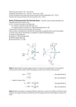
Ratio of driving tension for flat belt drive: - Consider a driven pulley rotating in the
clockwise direction as shown in Fig.
Let T1 = Tension in the belt on the tight side,
T2 = Tension in the belt on the slack side, and
θ = Angle of contact in radians (i.e. angle subtended by the arc AB,
Along which the belt touches the pulley, at the centre).
Now consider a small portion of the belt PQ, subtending an angle δθ at the centre of the pulley
as shown in Fig. 18.16. The belt PQ is in equilibrium under the following forces:
1. Tension T in the belt at P,
2. Tension (T + δT) in the belt at Q,
3. Normal reaction RN, and
4. Frictional force F = μ × RN
Notes: 1. While determining the angle of contact, it must be remembered that it is the angle of
contact at the smaller pulley, if both the pulleys are of the same material. We know that
Notes: 2. When the pulleys are made of different material (i.e. when the coefficient of friction of the
pulleys or the angle of contact are different), then the design will refer to the pulley for which μ.θ is
small.
Initial Tension: - When a belt is mounted on the pulley some amount of initial tension say ‘T0’ is
provided in the belt, otherwise power transmission is not possible because a loose belt cannot
sustain difference in the tension and no power can be transmitted.
When the drive is stationary the total tension on both sides will be ‘2 T0’.
When belt drive is transmitting power the total tension on both sides will be (T1 + T2), where T1 is
tension on tight side, and T2 is tension on the slack side.
If effect of centrifugal tension is neglected.
If effect of centrifugal tension is considered, then
Tension due to centrifugal force: - The belt has mass and as it rotates along with the pulley
it is subjected to centrifugal forces. If we assume that no power is being transmitted and pulleys are
rotating, the centrifugal force will tend to pull the belt as shown in Figure, thereby, a tension in the
belt called centrifugal tension will be introduced.
Let ‘TC’ be the centrifugal tension due to centrifugal force.
Let us consider a small element which subtends an angle  at the centre of the pulley.
Let ‘m’ be the mass of the belt per unit length of the belt in ‘kg/m’.
The centrifugal force ‘Fc’ on the element will be given by
Where V is speed of the belt in m/sec. and r is the radius of pulley in ‘m’.
Resolving the forces on the element normal to the tangent
Since  is very small.
Therefore, considering the effect of the centrifugal tension, the belt tension on the tight side when
power is transmitted is given by Tension of tight side and tension on the slack side.
4.2) Chains: - The belt drive is not a positive drive because of creep and slip. The chain drive is a
positive drive. Like belts, chains can be used for larger centre distances. They are made of metal and
due to this chain is heavier than the belt but they are flexible like belts. It also requires lubrication
from time to time. The lubricant prevents chain from rusting and reduces wear.
The sprockets are used in place of pulleys. The projected teeth of sprockets fit in the recesses of the
chain. The distance between roller centres’ of two adjacent links is known as pitch. The circle passing
through the pitch centres is called pitch circle.
The chains are mostly used to transmit motion and power from one shaft to another, when the
Centre distance between their shafts is short such as in bicycles, motor cycles, agricultural
machinery, conveyors, rolling mills, road rollers etc. The chains may also be used for long centre
distance of up to 8 metres. The chains are used for velocities up to 25 m / s and for power up to 110
kW. In some cases, higher power transmission is also possible.
Advantages and Disadvantages of Chain Drive over Belt or Rope Drive
Advantages:-
1. As no slip takes place during chain drive, hence perfect velocity ratio is obtained.
2. Since the chains are made of metal, therefore they occupy less space in width than a belt or
Rope drive.
3. It may be used for both long as well as short distances.
4. It gives a high transmission efficiency (up to 98 percent).
5. It gives less load on the shafts.
6. It has the ability to transmit motion to several shafts by one chain only.
7. It transmits more power than belts.
8. It permits high speed ratio of 8 to 10 in one step.
9. It can be operated under adverse temperature and atmospheric conditions.
Disadvantages:-
1. The production cost of chains is relatively high.
2. The chain drive needs accurate mounting and careful maintenance, particularly lubrication
and slack adjustment.
2. The chain drive has velocity fluctuations especially when unduly stretched.
Classifications of chain:-
The chains, on the basis of their use, are classified into the following three groups:
1. Hoisting and hauling (or crane) chains,
2. Conveyor (or tractive) chains, and
3. Power transmitting (or driving) chains.
Velocity ratio of chain drive:-
The velocity ratio of a chain drive is given by
N1 = Speed of rotation of smaller sprocket in r.p.m.,
N2 = Speed of rotation of larger sprocket in r.p.m.,
T1 = Number of teeth on the smaller sprocket, and
T2 = Number of teeth on the larger sprocket.
The average velocity of the chain is given by
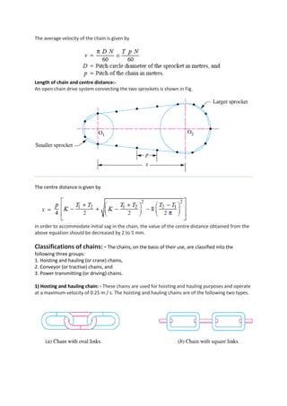
Length of chain and centre distance:-
An open chain drive system connecting the two sprockets is shown in Fig.
The centre distance is given by
In order to accommodate initial sag in the chain, the value of the centre distance obtained from the
above equation should be decreased by 2 to 5 mm.
Classifications of chains: - The chains, on the basis of their use, are classified into the
following three groups:
1. Hoisting and hauling (or crane) chains,
2. Conveyor (or tractive) chains, and
3. Power transmitting (or driving) chains.
1) Hosting and hauling chain: - These chains are used for hoisting and hauling purposes and operate
at a maximum velocity of 0.25 m / s. The hoisting and hauling chains are of the following two types.
Chain with oval links: - The links of this type of chain are of oval shape, as shown in Fig. The joint of
each link is welded. The sprockets which are used for this type of chain have receptacles to receive
the links. Such type of chains are used only at low speeds such as in chain hoists and in anchors for
marine works.
Chain with square links: - The links of this type of chain are of square shape, as shown in Fig. Such
type of chains are used in hoists, cranes, dredges. The manufacturing cost of this type of chain is less
than that of chain with oval links, but in these chains, the kinking occurs easily on overloading.
2) Conveyor Chain: - These chains are used for elevating and conveying the materials continuously at
a speed up to 2 m / s. The conveyor chains are usually made of malleable cast iron. These chains do
not have smooth running qualities. The conveyor chains run at slow speeds of about 0.8 to 3 m / s.
The conveyor chains are of the following two types.
3) Power transmitting chain: - These chains are used for transmission of power, when the distance
between the centres of shafts is short. These chains have provision for efficient lubrication. The
power transmitting chains are of the following three types.
3.1. Block or bush chain: - This type of chain was used in the early stages of development in the
power transmission. It produces noise when approaching or leaving the teeth of the sprocket
because of rubbing between the teeth and the links. Such type of chains are used to some extent as
conveyor chain at small speed.
3.2. Bush roller chain: - It consists of outer plates or pin link plates, inner plates or roller link plates,
pins, bushes and rollers. A pin passes through the bush which is secured in the holes of the roller
between the two sides of the chain. The rollers are free to rotate on the bush which protect the
sprocket wheel teeth against wear. The pins, bushes and rollers are made of alloy steel. There is a
little noise with this chain which is due to impact of the rollers on the sprocket wheel teeth. This
chain may be used where there is a little lubrication.
3.3. Silent chain: - It is designed to eliminate the evil effects caused by stretching and to produce
noiseless running. When the chain stretches and the pitch of the chain increases, the links ride on
the teeth of the sprocket wheel at a slightly increased radius. This automatically corrects the small
change in the pitch. There is no relative sliding between the teeth of the inverted tooth chain and
the sprocket wheel teeth. When properly lubricated, this chain gives durable service and runs very
smoothly and quietly.
Characteristics of roller chain:-
4.3) Gears: - Gears are mechanisms that mesh together via teeth and are used to transmit rotary
motion from one shaft to another. Gears are defined by two important items: radius and number of
teeth. They are typically mounted, or connected to other parts, via a shaft or base.
Classification of Gear: - Gears are most common means used for power transmission they can be
applied between two shafts which are parallel or perpendicular, perpendicular and intersecting,
perpendicular and non-intersecting.
The drive between the two gears can be represented by using plain cylinders or discs 1 and 2 having
diameters equal to their pitch circles as shown in Figure 3.5. The point of contact of the two pitch
surfaces shell have velocity along the common tangent. Because there is no slip, definite motion of
gear 1 can be transmitted to gear 2 or vice-versa.
The tangential velocity ‘Vp’ = 1 r1 = 2 r2
Where r1 and r2 are pitch circle radii of gears 1 and 2, respectively.
Since, pitch circle radius of a gear is proportional to its number of teeth (t).
Where t1 and t2 are the number of teeth on gears 1 and 2, respectively.
Summary: - The power transmission devices are belt drive, chain drive and gear drive. The belt
drive is used when distance between the shaft axes is large and there is no effect of slip on power
transmission. Chain drive is used for intermediate distance. Gear drive is used for short centre
distance. The gear drive and chain drive are positive drives but they are comparatively costlier than
belt drive.
Similarly, belt drive should satisfy law of belting otherwise it will slip to the side and drive cannot be
performed. When belt drive transmits power, one side will become tight side and other side will
become loose side. The ratio of tension depends on the angle of lap and coefficient of friction. If
coefficient of friction is same on both the pulleys smaller angle of lap will be used in the formula. If
coefficient of friction is different, the minimum value of product of coefficient of friction and angle
of lap will decide the ratio of tension, i.e. power transmitted. Due to the mass of belt, centrifugal
tension acts and reduces power transmitted. For a given belt drive the power transmitted will be
maximum at a speed for which centrifugal tension is one third of maximum possible tension.
The gears can be classified according to the layout of their shafts. For parallel shafts spur or helical
gears are used and bevel gears are used for intersecting shafts. For skew shafts when angle between
the axes is 90o worm and worm gears are used. When distance between the axes of shaft is larger
and positive drive is required, chain drive is used. We can see the use of chain drive in case of tanks,
motorcycles, etc.

More Related Content

What's hot

Two speed gear box mini project
Two speed gear box mini projectTwo speed gear box mini project
Two speed gear box mini project
Aravind Ganesh
 
Power transmission devices
Power transmission devicesPower transmission devices
Power transmission devices
AISSMS IOIT,PUNE
 
Wire rope design
Wire rope design Wire rope design
Wire rope design
gosavianiruddha
 
Srlection of Belts (V-Belt)
Srlection of Belts (V-Belt)Srlection of Belts (V-Belt)
Srlection of Belts (V-Belt)
Vaibhav Pardeshi
 
Chain Drives
Chain DrivesChain Drives
Chain Drives
VARUN BABUNELSON
 
V belt and rope drives
V belt and rope drivesV belt and rope drives
V belt and rope drives
Mohamed Mohamed El-Sayed
 
Belt, rope and chain drives
Belt, rope and chain drivesBelt, rope and chain drives
Belt, rope and chain drives
MANJUNATH N
 
Screw jack project_1
Screw jack project_1Screw jack project_1
Screw jack project_1
Ethiopia University
 
Belt conveyor
Belt conveyorBelt conveyor
Belt conveyor
Ankit Narain
 
Introduction to Mechanisms
Introduction to MechanismsIntroduction to Mechanisms
Chain drive system
Chain drive systemChain drive system
Chain drive system
Bhagyashri Dhage
 
Design and construction of a Universal Couling
Design and construction of a Universal CoulingDesign and construction of a Universal Couling
Design and construction of a Universal Couling
Md Shariful Islam
 
Clutches - Working and Application
Clutches - Working and ApplicationClutches - Working and Application
Clutches - Working and Application
Utsav Jain
 
BELT CONVEYORS
BELT CONVEYORSBELT CONVEYORS
BELT CONVEYORS
Chandana R
 
Design of bearing
Design of bearingDesign of bearing
Design of bearing
gosavianiruddha
 
Chain drives
Chain drivesChain drives
Chain Drives Selection - Solved Problem
Chain Drives Selection - Solved ProblemChain Drives Selection - Solved Problem
Chain Drives Selection - Solved Problem
VARUN BABUNELSON
 

What's hot (20)

Two speed gear box mini project
Two speed gear box mini projectTwo speed gear box mini project
Two speed gear box mini project
 
Power transmission devices
Power transmission devicesPower transmission devices
Power transmission devices
 
Wire rope design
Wire rope design Wire rope design
Wire rope design
 
Srlection of Belts (V-Belt)
Srlection of Belts (V-Belt)Srlection of Belts (V-Belt)
Srlection of Belts (V-Belt)
 
Chain Drives
Chain DrivesChain Drives
Chain Drives
 
V belt and rope drives
V belt and rope drivesV belt and rope drives
V belt and rope drives
 
Belt conveyor _2_
Belt conveyor _2_Belt conveyor _2_
Belt conveyor _2_
 
Belt, rope and chain drives
Belt, rope and chain drivesBelt, rope and chain drives
Belt, rope and chain drives
 
Screw jack project_1
Screw jack project_1Screw jack project_1
Screw jack project_1
 
Belt conveyor
Belt conveyorBelt conveyor
Belt conveyor
 
Introduction to Mechanisms
Introduction to MechanismsIntroduction to Mechanisms
Introduction to Mechanisms
 
Chain drive system
Chain drive systemChain drive system
Chain drive system
 
Gear train
Gear trainGear train
Gear train
 
Screw Jack Design
Screw Jack DesignScrew Jack Design
Screw Jack Design
 
Design and construction of a Universal Couling
Design and construction of a Universal CoulingDesign and construction of a Universal Couling
Design and construction of a Universal Couling
 
Clutches - Working and Application
Clutches - Working and ApplicationClutches - Working and Application
Clutches - Working and Application
 
BELT CONVEYORS
BELT CONVEYORSBELT CONVEYORS
BELT CONVEYORS
 
Design of bearing
Design of bearingDesign of bearing
Design of bearing
 
Chain drives
Chain drivesChain drives
Chain drives
 
Chain Drives Selection - Solved Problem
Chain Drives Selection - Solved ProblemChain Drives Selection - Solved Problem
Chain Drives Selection - Solved Problem
 

Similar to A review paper on mechanical power transmission system converted

Belt and Rope drives
Belt and Rope drivesBelt and Rope drives
Belt and Rope drives
Muhammad Yahya
 
Belt Drives_1.pptx
Belt Drives_1.pptxBelt Drives_1.pptx
Belt Drives_1.pptx
HarikumarA4
 
Design of Belt Drives With Pulley Theory By Prof. Sagar A. Dhotare
Design of Belt Drives With Pulley Theory By Prof. Sagar A. DhotareDesign of Belt Drives With Pulley Theory By Prof. Sagar A. Dhotare
Design of Belt Drives With Pulley Theory By Prof. Sagar A. Dhotare
Sagar Dhotare
 
BELT DRIVE.pptx, machine element two chapter 3
BELT DRIVE.pptx, machine element two chapter 3BELT DRIVE.pptx, machine element two chapter 3
BELT DRIVE.pptx, machine element two chapter 3
haymanot16
 
DESIGN OF TRANSMISSION SYSTEMS-Belt drive
DESIGN OF TRANSMISSION SYSTEMS-Belt driveDESIGN OF TRANSMISSION SYSTEMS-Belt drive
DESIGN OF TRANSMISSION SYSTEMS-Belt drive
Chandra Kumar S
 
belt_drive.ppt
belt_drive.pptbelt_drive.ppt
belt_drive.ppt
dinesh babu
 
Lecture_18-19_Flat Belt Drive.pptx
Lecture_18-19_Flat Belt Drive.pptxLecture_18-19_Flat Belt Drive.pptx
Lecture_18-19_Flat Belt Drive.pptx
AbdullahRiaz61
 
Belt Drive
Belt DriveBelt Drive
Belt Drive
Rohit Singla
 
Conveyor Belt Dynamics.pptx
Conveyor Belt Dynamics.pptxConveyor Belt Dynamics.pptx
Conveyor Belt Dynamics.pptx
SomdeepSarkar
 
Chain and belt drive
Chain and belt driveChain and belt drive
Chain and belt drive
Akash Lal
 
Flat belt drives
Flat belt drivesFlat belt drives
Flat belt drives
Mohamed Mohamed El-Sayed
 
hmhmhmhmhmhmhmjPC-ME503_14200721019.pptx
hmhmhmhmhmhmhmjPC-ME503_14200721019.pptxhmhmhmhmhmhmhmjPC-ME503_14200721019.pptx
hmhmhmhmhmhmhmjPC-ME503_14200721019.pptx
saptarshichatterjee33
 
Mechanisms of Textile Machine
Mechanisms of Textile MachineMechanisms of Textile Machine
Mechanisms of Textile Machine
Muktar Seid Hussen
 
Lec5.pptx
Lec5.pptxLec5.pptx
Lec5.pptx
SherAli984263
 
Poewr transmission
Poewr transmissionPoewr transmission
Poewr transmission
Mizanur Rehman Shobuj
 
Ring frame
Ring frame Ring frame
Ring frame
Sadia Textile
 
Belt drive sYSTEM
Belt drive sYSTEMBelt drive sYSTEM
Belt drive sYSTEM
Bhagyashri Dhage
 
Design of Transmission Systems
Design of Transmission SystemsDesign of Transmission Systems
Design of Transmission Systems
Devan P.D
 
Conveyor Belt 1 JUNE.PPTX
Conveyor Belt 1 JUNE.PPTXConveyor Belt 1 JUNE.PPTX
Conveyor Belt 1 JUNE.PPTX
NEHAKUMARI871825
 

Similar to A review paper on mechanical power transmission system converted (20)

Belt and Rope drives
Belt and Rope drivesBelt and Rope drives
Belt and Rope drives
 
Belt Drives_1.pptx
Belt Drives_1.pptxBelt Drives_1.pptx
Belt Drives_1.pptx
 
Design of Belt Drives With Pulley Theory By Prof. Sagar A. Dhotare
Design of Belt Drives With Pulley Theory By Prof. Sagar A. DhotareDesign of Belt Drives With Pulley Theory By Prof. Sagar A. Dhotare
Design of Belt Drives With Pulley Theory By Prof. Sagar A. Dhotare
 
BELT DRIVE.pptx, machine element two chapter 3
BELT DRIVE.pptx, machine element two chapter 3BELT DRIVE.pptx, machine element two chapter 3
BELT DRIVE.pptx, machine element two chapter 3
 
DESIGN OF TRANSMISSION SYSTEMS-Belt drive
DESIGN OF TRANSMISSION SYSTEMS-Belt driveDESIGN OF TRANSMISSION SYSTEMS-Belt drive
DESIGN OF TRANSMISSION SYSTEMS-Belt drive
 
belt_drive.ppt
belt_drive.pptbelt_drive.ppt
belt_drive.ppt
 
Lecture_18-19_Flat Belt Drive.pptx
Lecture_18-19_Flat Belt Drive.pptxLecture_18-19_Flat Belt Drive.pptx
Lecture_18-19_Flat Belt Drive.pptx
 
Belt Drive
Belt DriveBelt Drive
Belt Drive
 
Conveyor Belt Dynamics.pptx
Conveyor Belt Dynamics.pptxConveyor Belt Dynamics.pptx
Conveyor Belt Dynamics.pptx
 
Belt drive
Belt driveBelt drive
Belt drive
 
Chain and belt drive
Chain and belt driveChain and belt drive
Chain and belt drive
 
Flat belt drives
Flat belt drivesFlat belt drives
Flat belt drives
 
hmhmhmhmhmhmhmjPC-ME503_14200721019.pptx
hmhmhmhmhmhmhmjPC-ME503_14200721019.pptxhmhmhmhmhmhmhmjPC-ME503_14200721019.pptx
hmhmhmhmhmhmhmjPC-ME503_14200721019.pptx
 
Mechanisms of Textile Machine
Mechanisms of Textile MachineMechanisms of Textile Machine
Mechanisms of Textile Machine
 
Lec5.pptx
Lec5.pptxLec5.pptx
Lec5.pptx
 
Poewr transmission
Poewr transmissionPoewr transmission
Poewr transmission
 
Ring frame
Ring frame Ring frame
Ring frame
 
Belt drive sYSTEM
Belt drive sYSTEMBelt drive sYSTEM
Belt drive sYSTEM
 
Design of Transmission Systems
Design of Transmission SystemsDesign of Transmission Systems
Design of Transmission Systems
 
Conveyor Belt 1 JUNE.PPTX
Conveyor Belt 1 JUNE.PPTXConveyor Belt 1 JUNE.PPTX
Conveyor Belt 1 JUNE.PPTX
 

Recently uploaded

HYDROPOWER - Hydroelectric power generation
HYDROPOWER - Hydroelectric power generationHYDROPOWER - Hydroelectric power generation
HYDROPOWER - Hydroelectric power generation
Robbie Edward Sayers
 
ASME IX(9) 2007 Full Version .pdf
ASME IX(9)  2007 Full Version       .pdfASME IX(9)  2007 Full Version       .pdf
ASME IX(9) 2007 Full Version .pdf
AhmedHussein950959
 
MCQ Soil mechanics questions (Soil shear strength).pdf
MCQ Soil mechanics questions (Soil shear strength).pdfMCQ Soil mechanics questions (Soil shear strength).pdf
MCQ Soil mechanics questions (Soil shear strength).pdf
Osamah Alsalih
 
Top 10 Oil and Gas Projects in Saudi Arabia 2024.pdf
Top 10 Oil and Gas Projects in Saudi Arabia 2024.pdfTop 10 Oil and Gas Projects in Saudi Arabia 2024.pdf
Top 10 Oil and Gas Projects in Saudi Arabia 2024.pdf
Teleport Manpower Consultant
 
Immunizing Image Classifiers Against Localized Adversary Attacks
Immunizing Image Classifiers Against Localized Adversary AttacksImmunizing Image Classifiers Against Localized Adversary Attacks
Immunizing Image Classifiers Against Localized Adversary Attacks
gerogepatton
 
J.Yang, ICLR 2024, MLILAB, KAIST AI.pdf
J.Yang,  ICLR 2024, MLILAB, KAIST AI.pdfJ.Yang,  ICLR 2024, MLILAB, KAIST AI.pdf
J.Yang, ICLR 2024, MLILAB, KAIST AI.pdf
MLILAB
 
一比一原版(SFU毕业证)西蒙菲莎大学毕业证成绩单如何办理
一比一原版(SFU毕业证)西蒙菲莎大学毕业证成绩单如何办理一比一原版(SFU毕业证)西蒙菲莎大学毕业证成绩单如何办理
一比一原版(SFU毕业证)西蒙菲莎大学毕业证成绩单如何办理
bakpo1
 
COLLEGE BUS MANAGEMENT SYSTEM PROJECT REPORT.pdf
COLLEGE BUS MANAGEMENT SYSTEM PROJECT REPORT.pdfCOLLEGE BUS MANAGEMENT SYSTEM PROJECT REPORT.pdf
COLLEGE BUS MANAGEMENT SYSTEM PROJECT REPORT.pdf
Kamal Acharya
 
Industrial Training at Shahjalal Fertilizer Company Limited (SFCL)
Industrial Training at Shahjalal Fertilizer Company Limited (SFCL)Industrial Training at Shahjalal Fertilizer Company Limited (SFCL)
Industrial Training at Shahjalal Fertilizer Company Limited (SFCL)
MdTanvirMahtab2
 
AKS UNIVERSITY Satna Final Year Project By OM Hardaha.pdf
AKS UNIVERSITY Satna Final Year Project By OM Hardaha.pdfAKS UNIVERSITY Satna Final Year Project By OM Hardaha.pdf
AKS UNIVERSITY Satna Final Year Project By OM Hardaha.pdf
SamSarthak3
 
Pile Foundation by Venkatesh Taduvai (Sub Geotechnical Engineering II)-conver...
Pile Foundation by Venkatesh Taduvai (Sub Geotechnical Engineering II)-conver...Pile Foundation by Venkatesh Taduvai (Sub Geotechnical Engineering II)-conver...
Pile Foundation by Venkatesh Taduvai (Sub Geotechnical Engineering II)-conver...
AJAYKUMARPUND1
 
Courier management system project report.pdf
Courier management system project report.pdfCourier management system project report.pdf
Courier management system project report.pdf
Kamal Acharya
 
Quality defects in TMT Bars, Possible causes and Potential Solutions.
Quality defects in TMT Bars, Possible causes and Potential Solutions.Quality defects in TMT Bars, Possible causes and Potential Solutions.
Quality defects in TMT Bars, Possible causes and Potential Solutions.
PrashantGoswami42
 
ethical hacking in wireless-hacking1.ppt
ethical hacking in wireless-hacking1.pptethical hacking in wireless-hacking1.ppt
ethical hacking in wireless-hacking1.ppt
Jayaprasanna4
 
Vaccine management system project report documentation..pdf
Vaccine management system project report documentation..pdfVaccine management system project report documentation..pdf
Vaccine management system project report documentation..pdf
Kamal Acharya
 
block diagram and signal flow graph representation
block diagram and signal flow graph representationblock diagram and signal flow graph representation
block diagram and signal flow graph representation
Divya Somashekar
 
Water Industry Process Automation and Control Monthly - May 2024.pdf
Water Industry Process Automation and Control Monthly - May 2024.pdfWater Industry Process Automation and Control Monthly - May 2024.pdf
Water Industry Process Automation and Control Monthly - May 2024.pdf
Water Industry Process Automation & Control
 
在线办理(ANU毕业证书)澳洲国立大学毕业证录取通知书一模一样
在线办理(ANU毕业证书)澳洲国立大学毕业证录取通知书一模一样在线办理(ANU毕业证书)澳洲国立大学毕业证录取通知书一模一样
在线办理(ANU毕业证书)澳洲国立大学毕业证录取通知书一模一样
obonagu
 
Planning Of Procurement o different goods and services
Planning Of Procurement o different goods and servicesPlanning Of Procurement o different goods and services
Planning Of Procurement o different goods and services
JoytuBarua2
 
ethical hacking-mobile hacking methods.ppt
ethical hacking-mobile hacking methods.pptethical hacking-mobile hacking methods.ppt
ethical hacking-mobile hacking methods.ppt
Jayaprasanna4
 

Recently uploaded (20)

HYDROPOWER - Hydroelectric power generation
HYDROPOWER - Hydroelectric power generationHYDROPOWER - Hydroelectric power generation
HYDROPOWER - Hydroelectric power generation
 
ASME IX(9) 2007 Full Version .pdf
ASME IX(9)  2007 Full Version       .pdfASME IX(9)  2007 Full Version       .pdf
ASME IX(9) 2007 Full Version .pdf
 
MCQ Soil mechanics questions (Soil shear strength).pdf
MCQ Soil mechanics questions (Soil shear strength).pdfMCQ Soil mechanics questions (Soil shear strength).pdf
MCQ Soil mechanics questions (Soil shear strength).pdf
 
Top 10 Oil and Gas Projects in Saudi Arabia 2024.pdf
Top 10 Oil and Gas Projects in Saudi Arabia 2024.pdfTop 10 Oil and Gas Projects in Saudi Arabia 2024.pdf
Top 10 Oil and Gas Projects in Saudi Arabia 2024.pdf
 
Immunizing Image Classifiers Against Localized Adversary Attacks
Immunizing Image Classifiers Against Localized Adversary AttacksImmunizing Image Classifiers Against Localized Adversary Attacks
Immunizing Image Classifiers Against Localized Adversary Attacks
 
J.Yang, ICLR 2024, MLILAB, KAIST AI.pdf
J.Yang,  ICLR 2024, MLILAB, KAIST AI.pdfJ.Yang,  ICLR 2024, MLILAB, KAIST AI.pdf
J.Yang, ICLR 2024, MLILAB, KAIST AI.pdf
 
一比一原版(SFU毕业证)西蒙菲莎大学毕业证成绩单如何办理
一比一原版(SFU毕业证)西蒙菲莎大学毕业证成绩单如何办理一比一原版(SFU毕业证)西蒙菲莎大学毕业证成绩单如何办理
一比一原版(SFU毕业证)西蒙菲莎大学毕业证成绩单如何办理
 
COLLEGE BUS MANAGEMENT SYSTEM PROJECT REPORT.pdf
COLLEGE BUS MANAGEMENT SYSTEM PROJECT REPORT.pdfCOLLEGE BUS MANAGEMENT SYSTEM PROJECT REPORT.pdf
COLLEGE BUS MANAGEMENT SYSTEM PROJECT REPORT.pdf
 
Industrial Training at Shahjalal Fertilizer Company Limited (SFCL)
Industrial Training at Shahjalal Fertilizer Company Limited (SFCL)Industrial Training at Shahjalal Fertilizer Company Limited (SFCL)
Industrial Training at Shahjalal Fertilizer Company Limited (SFCL)
 
AKS UNIVERSITY Satna Final Year Project By OM Hardaha.pdf
AKS UNIVERSITY Satna Final Year Project By OM Hardaha.pdfAKS UNIVERSITY Satna Final Year Project By OM Hardaha.pdf
AKS UNIVERSITY Satna Final Year Project By OM Hardaha.pdf
 
Pile Foundation by Venkatesh Taduvai (Sub Geotechnical Engineering II)-conver...
Pile Foundation by Venkatesh Taduvai (Sub Geotechnical Engineering II)-conver...Pile Foundation by Venkatesh Taduvai (Sub Geotechnical Engineering II)-conver...
Pile Foundation by Venkatesh Taduvai (Sub Geotechnical Engineering II)-conver...
 
Courier management system project report.pdf
Courier management system project report.pdfCourier management system project report.pdf
Courier management system project report.pdf
 
Quality defects in TMT Bars, Possible causes and Potential Solutions.
Quality defects in TMT Bars, Possible causes and Potential Solutions.Quality defects in TMT Bars, Possible causes and Potential Solutions.
Quality defects in TMT Bars, Possible causes and Potential Solutions.
 
ethical hacking in wireless-hacking1.ppt
ethical hacking in wireless-hacking1.pptethical hacking in wireless-hacking1.ppt
ethical hacking in wireless-hacking1.ppt
 
Vaccine management system project report documentation..pdf
Vaccine management system project report documentation..pdfVaccine management system project report documentation..pdf
Vaccine management system project report documentation..pdf
 
block diagram and signal flow graph representation
block diagram and signal flow graph representationblock diagram and signal flow graph representation
block diagram and signal flow graph representation
 
Water Industry Process Automation and Control Monthly - May 2024.pdf
Water Industry Process Automation and Control Monthly - May 2024.pdfWater Industry Process Automation and Control Monthly - May 2024.pdf
Water Industry Process Automation and Control Monthly - May 2024.pdf
 
在线办理(ANU毕业证书)澳洲国立大学毕业证录取通知书一模一样
在线办理(ANU毕业证书)澳洲国立大学毕业证录取通知书一模一样在线办理(ANU毕业证书)澳洲国立大学毕业证录取通知书一模一样
在线办理(ANU毕业证书)澳洲国立大学毕业证录取通知书一模一样
 
Planning Of Procurement o different goods and services
Planning Of Procurement o different goods and servicesPlanning Of Procurement o different goods and services
Planning Of Procurement o different goods and services
 
ethical hacking-mobile hacking methods.ppt
ethical hacking-mobile hacking methods.pptethical hacking-mobile hacking methods.ppt
ethical hacking-mobile hacking methods.ppt
 

A review paper on mechanical power transmission system converted

  • 1. A Review Paper on Mechanical Power Transmission System Roshan Tiwari B.E (Mechanical Engineering) Structure:- 1. Introduction 2. Machine Elements 3. Types of Transmission 1.Automatic Transmission 2.Manual Transmission 3.Automated manual Transmission 4.Continuosly manual Transmission 4. Power Transmission Device 1.Belts 2.Chain 3.Gears 5. Power Transmission by Belts 1. Law of Belting 2. Length of an open belt drive 3. Length of an crossed belt drive 4. Maximum Power Transmitted 5. Ratio of driving tension for flat belt drive 6. Initial tension 7. Tension due to centrifugal force 6. Summary
  • 2. 1. Introduction: - In an industrial facility, motors and turbines use energy to produce rotational mechanical motion. The Mechanical Transmission Systems subject area covers these types of transmission systems, including specific applications, how each works, and basic maintenance procedures. Mechanical power transmission refers to products used in systems with moving parts as opposed to systems powered electrically. These products include shaft couplings, chains and sprockets, belts and sheaves, and drive components. Power transmission is the movement of energy from its place of generation to a location where it is applied to perform useful work. Power is defined formally as units of energy per unit time. In SI units: Watt = Joule/Second = Newton meter/Second 2. Machine Elements: - Machine element is an individual component or group of component of a machine which perform a specific function. Depending upon this functions only, the machine elements are following types. 1) Machine elements used for holding the components. 2) Machine elements used for transmitting the power. 3) Machine elements used for support the other components. 3. Types of Transmission: - There are mainly four type of transmission type which are described below. 1) Automatic Transmission 2) Manual Transmission 3) Automated Manual Transmission 4) Continuously Variable Transmission Automatic Transmission:- This is a transmission that uses a torque converter, planetary gear set and clutches or bands to shift through a vehicle's forward gears automatically. Some automatics allow the driver a limited amount of manual control over the vehicle (aside from choosing a forward, reverse or neutral mode) -- for example allowing the driver to control upshifts and downshifts by utilizing buttons or paddles on the steering wheel or the gear selector. Manual Transmission: - With a manual transmission, the driver selects all gears manually using both a movable gear selector and a driver-operated clutch. This type of transmission is also known as a standard" transmission. Automated Manual Transmission: - Like a manual transmission, an automated manual also employs a mechanical clutch; however, the action of the clutch is not controlled by the driver via the clutch pedal but rather is automated using electronic, pneumatic or hydraulic controls. Continuously Variable Transmission: - This transmission has a continuously variable drive ratio (as opposed to conventionally stepped gear ratios) and uses belts, pulleys and sensors rather than gears to maintain a steady acceleration curve with no pauses for gear changes. Because of this, a CVT can keep the engine in its optimum power range, thereby increasing efficiency and gas mileage. 4. Power Transmission device: - Power transmission devices are very commonly used to transmit power from one shaft to another. Belts, chains, rope and gears are used for this purpose.
  • 3. 4.1) Belt Drive: - Belt, Chain and rope are called flexible drives. There are two types of drives rigid and flexible drive, gear drives are called rigid or non-flexible drives. In flexible drive there intermediate link such as belt, chain or rope between the driving and driven shaft since this link is flexible and so far this is called flexible drive. Types of Belt:- 1. Flat belt 2. V belt 3. Circular belt or rope 1) Flat Belt System: - This type consist of an endless belt fitted tightly over two pulleys (Driving & Driven) transmitting motion from the driving to the receiving pulley by frictional resistance between belt and pulleys. 2) V belt: - V-belt is mostly used in the factories and workshops, where a great amount of power is to be transmitted, from one pulley to another, when the two pulleys are very near to each other. 3) Circular belt: - The circular belt is mostly used in the factories and workshops, where a great amount of power is to be transmitted, from one pulley to another, when the two pulleys are more than 8 metres apart. If a huge amount of power is to be transmitted, then a single belt may not be sufficient. In such a case, wide pulleys (for V-belts or circular belts) with a number of grooves are used. Then a belt in Each groove is provided to transmit the required amount of power from one pulley to another. Following are the various important factors upon which the selection of belt drive depends. 1) Speed of the driving and driven shaft 2) Speed reduction ratio 3) Power to be transmitted 4) Centre distance between the shafts 5) Positive drive requirements 6) Shaft layout 7) Space available 8) Service Condition Types of belt drives:- 1) Light drives: - These are used for transmitting small power at belt speed up to 10 m/sec. 2) Medium drives: - These are used for transmitting at belt speed over 10m/sec up to 22m/sec. 3) Heavy drives: - These are used for transmitting large power at belt speed above 22m/sec. The material used for belt drives & ropes must be strong, flexible & durable. It must have high coefficient of friction. 1) Leather belts: - The most important material for flat belt is leather. The best leather belts are Made from 1.2 metres to 1.5 metres long strips cut from either side of the back bone of the top grade steer hides. The belts are specified according to the number of layers e.g. single, double or triple ply and according to the thickness of hides used e.g. light, medium or heavy. The leather belts must be periodically cleaned and dressed or treated with a compound or dressing containing neat’s foot or other suitable oils so that the belt will remain soft and flexible. 2) Cotton or fabric belts: - Most of the fabric belts are made by folding cotton duck to three or more layers (depending upon the thickness desired) and stitching together. These belts are woven also into a strip of the desired width and thickness. They are impregnated with some filler like linseed oil in order to make the belt water-proof and to prevent injury to the fibres. Since the cotton belts require little attention, therefore these belts are mostly used in farm machinery, belt Conveyor etc.
  • 4. 3) Rubber belt: - The rubber belts are made of layers of fabric impregnated with rubber composition and have a thin layer of rubber on the faces. These belts are very flexible but are quickly destroyed if allowed to come into contact with heat, oil or grease. One of the principle advantage of these belts is that they may be easily made endless. These belts are found suitable for saw mills, paper mills where they are exposed to moisture. 4) Balata belt: - These belts are similar to rubber belts except that balata gum is used in place of rubber. These belts are acid proof and water proof and it is not effected by animal oils or alkalis. The balata belts should not be at temperatures above 40°C because at this temperature the balata begins to soften and becomes sticky. The strength of balata belts is 25 per cent higher than rubber belts. Working Stresses in Belts:- The ultimate strength of leather belt varies from 21 to 35 MPa and a factor of safety may be taken as 8 to 10. However, the wear life of a belt is more important than actual strength. It has been shown by experience that under average conditions an allowable stress of 2.8 MPa or less will give a reasonable belt life. An allowable stress of 1.75 MPa may be expected to give a belt life of about 15 years. Density of Belt Materials:- The density of various belt materials are given in the following table. Material of belt Mass density in kg / m3 Leather 1000 Cotton 1220 Rubber 1140 Balata 1110 Single woven belt 1170 Double Woven belt 1250 Belt Speed:- A little consideration will show that when the speed of belt increases, the centrifugal force also increases which tries to pull the belt away from the pulley. This will result in the decrease of power transmitted by the belt. It has been found that for the efficient transmission of power, the belt speed 20 m/s to 22.5 m/s may be used. Standard Belt Thicknesses and Widths:- The standard flat belt thicknesses are 5, 6.5, 8, 10 and 12 mm. The preferred values of thicknesses are as follows. (a) 5 mm for nominal belt widths of 35 to 63 mm. (b) 6.5 mm for nominal belt widths of 50 to 140 mm. (c) 8 mm for nominal belt widths of 90 to 224 mm. (d) 10 mm for nominal belt widths of 125 to 400 mm. (e) 12 mm for nominal belt widths of 250 to 600 mm. The standard values of nominal belt widths are in R10 series, starting from 25 mm up to 63 mm and in R 20 series starting from 71 mm up to 600 mm. Thus, the standard widths will be 25, 32, 40, 50, 63, 71, 80, 90, 100, 112, 125, 140, 160, 180, 200, 224, 250, 280, 315, 355, 400, 450, 500, 560 and 600 mm.
  • 5. Belt Joints: - When the endless belts are not available, then the belts are cut from big rolls and the ends are joined together by fasteners. The various types of joints are 1) Cemented Joint: - Made by the manufacturer to form an endless belt is preferred than other joints. 2) Laced Joint: - The laced joint is formed by punching holes in line across the belt, leaving a margin between the edge and the holes. A raw hide strip is used for lacing the two ends together to form a joint. This type of joint is known as straight-stitch raw hide laced joint. 3) Hinged Joint: - Sometimes, metal hinges may be fastened to the belt ends and connected by a steel or fibre pin. Types of Flat belt drives:- The power from one pulley to another may be transmitted by any of the following types of belt drives. 1) Open belt drive: - The open belt drive is used with shafts arranged parallel and rotating in the same direction. In this case, the driver pulls the belt from one side and delivers it to the other side thus the tension in the lower side belt will be more than that in the upper side belt. The lower side belt (because of more tension) is known as tight side whereas the upper side belt (because of less tension) is known as slack side. 2) Crossed or twist belt drive: - The crossed or twist belt drive, as shown in Fig. 18.5, is used with Shafts arranged parallel and rotating in the opposite directions. In this case, the driver pulls the belt from one side (i.e. RQ) and delivers it to the other side (i.e. LM). Thus, the tension in the belt RQ will be more than that in the belt LM. The belt RQ (because of more tension) is known as tight side, Whereas the belt LM (because of less tension) is known as slack side. A little consideration will show that at a point where the belt crosses, it rubs against each other and there will be excessive wear and tear. In order to avoid this, the shafts should be placed at a maximum distance of 20 b, where b is the width of belt and the speed of the belt should be less than 15 m/s.
  • 6. 3) Quarter turn belt drive:- The quarter turn belt drive (also known as right angle belt drive), is used with shafts arranged at right angles and rotating in one definite direction. In order to prevent the belt from leaving the pulley, the width of the face of the pulley should be greater or equal to 1.4 b, where b is width of belt. In case the pulleys cannot be arranged or when the reversible motions desired, then a quarter turn belt drive with a guide pulley, may be used. 4) Belt drive with idler pulleys:- A belt drive with an idler pulley (also known as jockey pulley drive) is used with shafts arranged parallel and when an open belt drive cannot be used due to small angle of contact on the smaller pulley. This type of drive is provided to obtain high velocity ratio and when the required belt tension cannot be obtained by other means.
  • 7. 5) Compound belt drive: - A compound belt drive is used when power is transmitted from one shaft to another through a number of pulleys. Slip of the belt: - The motion of belts and pulleys assuming a firm frictional grip between the belts and the pulleys. But sometimes, the frictional grip becomes insufficient. This may cause some forward motion of the driver without carrying the belt with it. This is called slip of the belt and is generally expressed as a percentage. If thickness of the belt (t) is considered, then (Where S = s1 + s2 i.e. total percentage of slip) d1 = Diameter of the driver, d2 = Diameter of the follower, N1 = Speed of the driver in r.p.m., N2 = Speed of the follower in r.p.m.,
  • 8. Creep of belt: - When the belt passes from the slack side to the tight side, a certain portion of the belt extends and it contracts again when the belt passes from the tight side to the slack side. Due to these changes of length, there is a relative motion between the belt and the pulley surfaces. This relative motion is termed as creep. The total effect of creep is to reduce slightly the speed of the driven pulley or follower. Considering creep, the velocity ratio is given by Where  1 and  2= Stress in the belt on the tight and slack side respectively, and E = Young’s modulus for the material of the belt. Note: Since the effect of creep is very small, therefore it is generally neglected. Law of belting:- The law of belting state that the centre line of belt when it approaches a pulley must lie in the mid plane of that pulley. However, a belt leaving a pulley may be drawn out of the plane of the pulley. ... Otherwise, the belt is thrown off the pulley. Lenghth of an open belt drive:- In an open belt drive, both the pulleys rotate in the same direction as shown in Fig. Let r1 and r2 = Radii of the larger and smaller pulleys, x = Distance between the centres of two pulleys (i.e. O1O2), and L = Total length of the belt. α = angle of lap.
  • 9. Lenghth of an crosed belt drive:- In a cross belt drive, both the pulleys rotate in the opposite directions as shown in Fig. Let r1 and r2 = Radii of the larger and smaller pulleys, x = Distance between the centres of two pulleys (i.e. O1O2), and L = Total length of the belt. α = angle of lap. Power transmitted by a belt:- Driving pulley (or driver) A and the driven pulley (or follower) B. the driving pulley pulls the belt from one side and delivers it to the other side. It is thus obvious that the tension on the former side (i.e. tight side) will be greater than the latter side (i.e. Slack side) as shown in Fig. Let T1 and T2 = Tensions in the tight side and slack side of the belt respectively in newton’s, r1 and r2 = Radii of the driving and driven pulleys respectively in metres, and  = Velocity of the belt in m/s. The effective turning (driving) force at the circumference of the driven pulley or follower is the difference between the two tensions (i.e. T1 – T2).
  • 10. Work done per second = (T1 – T2) ν N-m/s and power transmitted = (T1 – T2) ν W ... (Q 1 N-m/s = 1W) A little consideration will show that torque exerted on the driving pulley is (T1 – T2) r1. Similarly, the torque exerted on the driven pulley is (T1 – T2) r2 Ratio of driving tension for flat belt drive: - Consider a driven pulley rotating in the clockwise direction as shown in Fig. Let T1 = Tension in the belt on the tight side, T2 = Tension in the belt on the slack side, and θ = Angle of contact in radians (i.e. angle subtended by the arc AB, Along which the belt touches the pulley, at the centre). Now consider a small portion of the belt PQ, subtending an angle δθ at the centre of the pulley as shown in Fig. 18.16. The belt PQ is in equilibrium under the following forces: 1. Tension T in the belt at P, 2. Tension (T + δT) in the belt at Q, 3. Normal reaction RN, and 4. Frictional force F = μ × RN Notes: 1. While determining the angle of contact, it must be remembered that it is the angle of contact at the smaller pulley, if both the pulleys are of the same material. We know that Notes: 2. When the pulleys are made of different material (i.e. when the coefficient of friction of the pulleys or the angle of contact are different), then the design will refer to the pulley for which μ.θ is small.
  • 11. Initial Tension: - When a belt is mounted on the pulley some amount of initial tension say ‘T0’ is provided in the belt, otherwise power transmission is not possible because a loose belt cannot sustain difference in the tension and no power can be transmitted. When the drive is stationary the total tension on both sides will be ‘2 T0’. When belt drive is transmitting power the total tension on both sides will be (T1 + T2), where T1 is tension on tight side, and T2 is tension on the slack side. If effect of centrifugal tension is neglected. If effect of centrifugal tension is considered, then Tension due to centrifugal force: - The belt has mass and as it rotates along with the pulley it is subjected to centrifugal forces. If we assume that no power is being transmitted and pulleys are rotating, the centrifugal force will tend to pull the belt as shown in Figure, thereby, a tension in the belt called centrifugal tension will be introduced. Let ‘TC’ be the centrifugal tension due to centrifugal force. Let us consider a small element which subtends an angle  at the centre of the pulley. Let ‘m’ be the mass of the belt per unit length of the belt in ‘kg/m’. The centrifugal force ‘Fc’ on the element will be given by Where V is speed of the belt in m/sec. and r is the radius of pulley in ‘m’. Resolving the forces on the element normal to the tangent
  • 12. Since  is very small. Therefore, considering the effect of the centrifugal tension, the belt tension on the tight side when power is transmitted is given by Tension of tight side and tension on the slack side. 4.2) Chains: - The belt drive is not a positive drive because of creep and slip. The chain drive is a positive drive. Like belts, chains can be used for larger centre distances. They are made of metal and due to this chain is heavier than the belt but they are flexible like belts. It also requires lubrication from time to time. The lubricant prevents chain from rusting and reduces wear. The sprockets are used in place of pulleys. The projected teeth of sprockets fit in the recesses of the chain. The distance between roller centres’ of two adjacent links is known as pitch. The circle passing through the pitch centres is called pitch circle.
  • 13. The chains are mostly used to transmit motion and power from one shaft to another, when the Centre distance between their shafts is short such as in bicycles, motor cycles, agricultural machinery, conveyors, rolling mills, road rollers etc. The chains may also be used for long centre distance of up to 8 metres. The chains are used for velocities up to 25 m / s and for power up to 110 kW. In some cases, higher power transmission is also possible. Advantages and Disadvantages of Chain Drive over Belt or Rope Drive Advantages:- 1. As no slip takes place during chain drive, hence perfect velocity ratio is obtained. 2. Since the chains are made of metal, therefore they occupy less space in width than a belt or Rope drive. 3. It may be used for both long as well as short distances. 4. It gives a high transmission efficiency (up to 98 percent). 5. It gives less load on the shafts. 6. It has the ability to transmit motion to several shafts by one chain only. 7. It transmits more power than belts. 8. It permits high speed ratio of 8 to 10 in one step. 9. It can be operated under adverse temperature and atmospheric conditions. Disadvantages:- 1. The production cost of chains is relatively high. 2. The chain drive needs accurate mounting and careful maintenance, particularly lubrication and slack adjustment. 2. The chain drive has velocity fluctuations especially when unduly stretched. Classifications of chain:- The chains, on the basis of their use, are classified into the following three groups: 1. Hoisting and hauling (or crane) chains, 2. Conveyor (or tractive) chains, and 3. Power transmitting (or driving) chains. Velocity ratio of chain drive:- The velocity ratio of a chain drive is given by N1 = Speed of rotation of smaller sprocket in r.p.m., N2 = Speed of rotation of larger sprocket in r.p.m., T1 = Number of teeth on the smaller sprocket, and T2 = Number of teeth on the larger sprocket.
  • 14. The average velocity of the chain is given by Length of chain and centre distance:- An open chain drive system connecting the two sprockets is shown in Fig. The centre distance is given by In order to accommodate initial sag in the chain, the value of the centre distance obtained from the above equation should be decreased by 2 to 5 mm. Classifications of chains: - The chains, on the basis of their use, are classified into the following three groups: 1. Hoisting and hauling (or crane) chains, 2. Conveyor (or tractive) chains, and 3. Power transmitting (or driving) chains. 1) Hosting and hauling chain: - These chains are used for hoisting and hauling purposes and operate at a maximum velocity of 0.25 m / s. The hoisting and hauling chains are of the following two types.
  • 15. Chain with oval links: - The links of this type of chain are of oval shape, as shown in Fig. The joint of each link is welded. The sprockets which are used for this type of chain have receptacles to receive the links. Such type of chains are used only at low speeds such as in chain hoists and in anchors for marine works. Chain with square links: - The links of this type of chain are of square shape, as shown in Fig. Such type of chains are used in hoists, cranes, dredges. The manufacturing cost of this type of chain is less than that of chain with oval links, but in these chains, the kinking occurs easily on overloading. 2) Conveyor Chain: - These chains are used for elevating and conveying the materials continuously at a speed up to 2 m / s. The conveyor chains are usually made of malleable cast iron. These chains do not have smooth running qualities. The conveyor chains run at slow speeds of about 0.8 to 3 m / s. The conveyor chains are of the following two types. 3) Power transmitting chain: - These chains are used for transmission of power, when the distance between the centres of shafts is short. These chains have provision for efficient lubrication. The power transmitting chains are of the following three types. 3.1. Block or bush chain: - This type of chain was used in the early stages of development in the power transmission. It produces noise when approaching or leaving the teeth of the sprocket because of rubbing between the teeth and the links. Such type of chains are used to some extent as conveyor chain at small speed. 3.2. Bush roller chain: - It consists of outer plates or pin link plates, inner plates or roller link plates, pins, bushes and rollers. A pin passes through the bush which is secured in the holes of the roller between the two sides of the chain. The rollers are free to rotate on the bush which protect the sprocket wheel teeth against wear. The pins, bushes and rollers are made of alloy steel. There is a little noise with this chain which is due to impact of the rollers on the sprocket wheel teeth. This chain may be used where there is a little lubrication. 3.3. Silent chain: - It is designed to eliminate the evil effects caused by stretching and to produce noiseless running. When the chain stretches and the pitch of the chain increases, the links ride on the teeth of the sprocket wheel at a slightly increased radius. This automatically corrects the small change in the pitch. There is no relative sliding between the teeth of the inverted tooth chain and the sprocket wheel teeth. When properly lubricated, this chain gives durable service and runs very smoothly and quietly.
  • 16. Characteristics of roller chain:- 4.3) Gears: - Gears are mechanisms that mesh together via teeth and are used to transmit rotary motion from one shaft to another. Gears are defined by two important items: radius and number of teeth. They are typically mounted, or connected to other parts, via a shaft or base. Classification of Gear: - Gears are most common means used for power transmission they can be applied between two shafts which are parallel or perpendicular, perpendicular and intersecting, perpendicular and non-intersecting. The drive between the two gears can be represented by using plain cylinders or discs 1 and 2 having diameters equal to their pitch circles as shown in Figure 3.5. The point of contact of the two pitch surfaces shell have velocity along the common tangent. Because there is no slip, definite motion of gear 1 can be transmitted to gear 2 or vice-versa. The tangential velocity ‘Vp’ = 1 r1 = 2 r2 Where r1 and r2 are pitch circle radii of gears 1 and 2, respectively.
  • 17. Since, pitch circle radius of a gear is proportional to its number of teeth (t). Where t1 and t2 are the number of teeth on gears 1 and 2, respectively. Summary: - The power transmission devices are belt drive, chain drive and gear drive. The belt drive is used when distance between the shaft axes is large and there is no effect of slip on power transmission. Chain drive is used for intermediate distance. Gear drive is used for short centre distance. The gear drive and chain drive are positive drives but they are comparatively costlier than belt drive. Similarly, belt drive should satisfy law of belting otherwise it will slip to the side and drive cannot be performed. When belt drive transmits power, one side will become tight side and other side will become loose side. The ratio of tension depends on the angle of lap and coefficient of friction. If coefficient of friction is same on both the pulleys smaller angle of lap will be used in the formula. If coefficient of friction is different, the minimum value of product of coefficient of friction and angle of lap will decide the ratio of tension, i.e. power transmitted. Due to the mass of belt, centrifugal tension acts and reduces power transmitted. For a given belt drive the power transmitted will be maximum at a speed for which centrifugal tension is one third of maximum possible tension. The gears can be classified according to the layout of their shafts. For parallel shafts spur or helical gears are used and bevel gears are used for intersecting shafts. For skew shafts when angle between the axes is 90o worm and worm gears are used. When distance between the axes of shaft is larger and positive drive is required, chain drive is used. We can see the use of chain drive in case of tanks, motorcycles, etc.