Downloaded 437 times
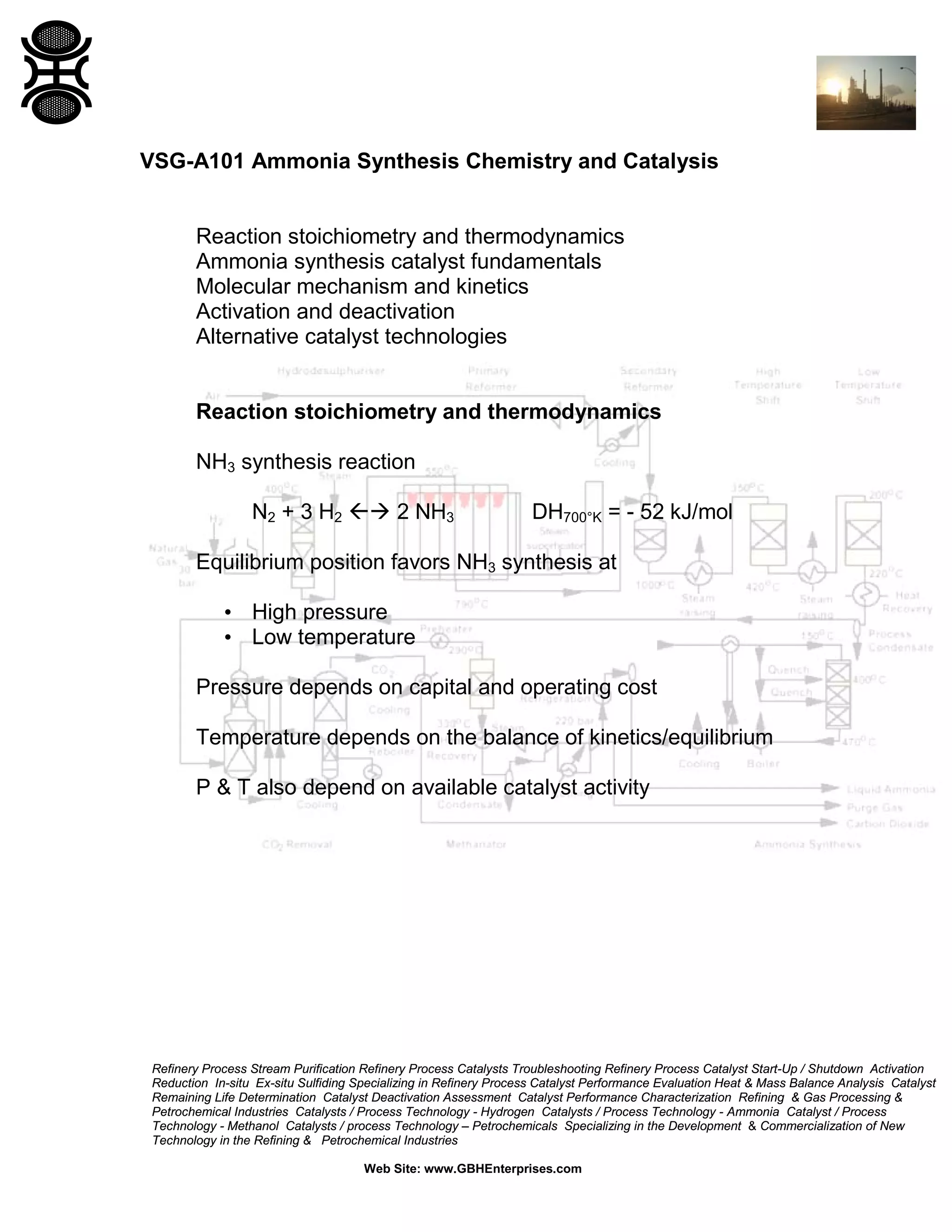
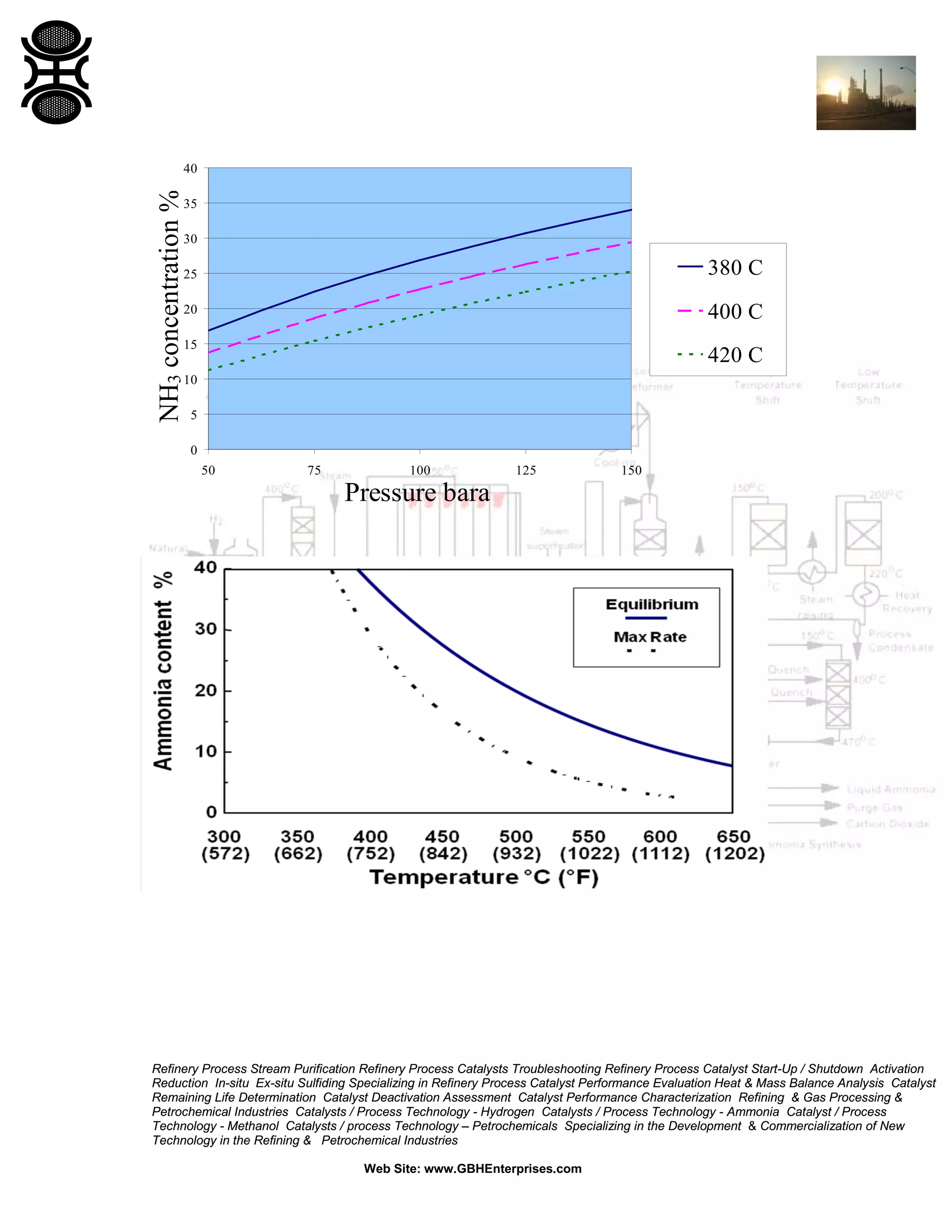
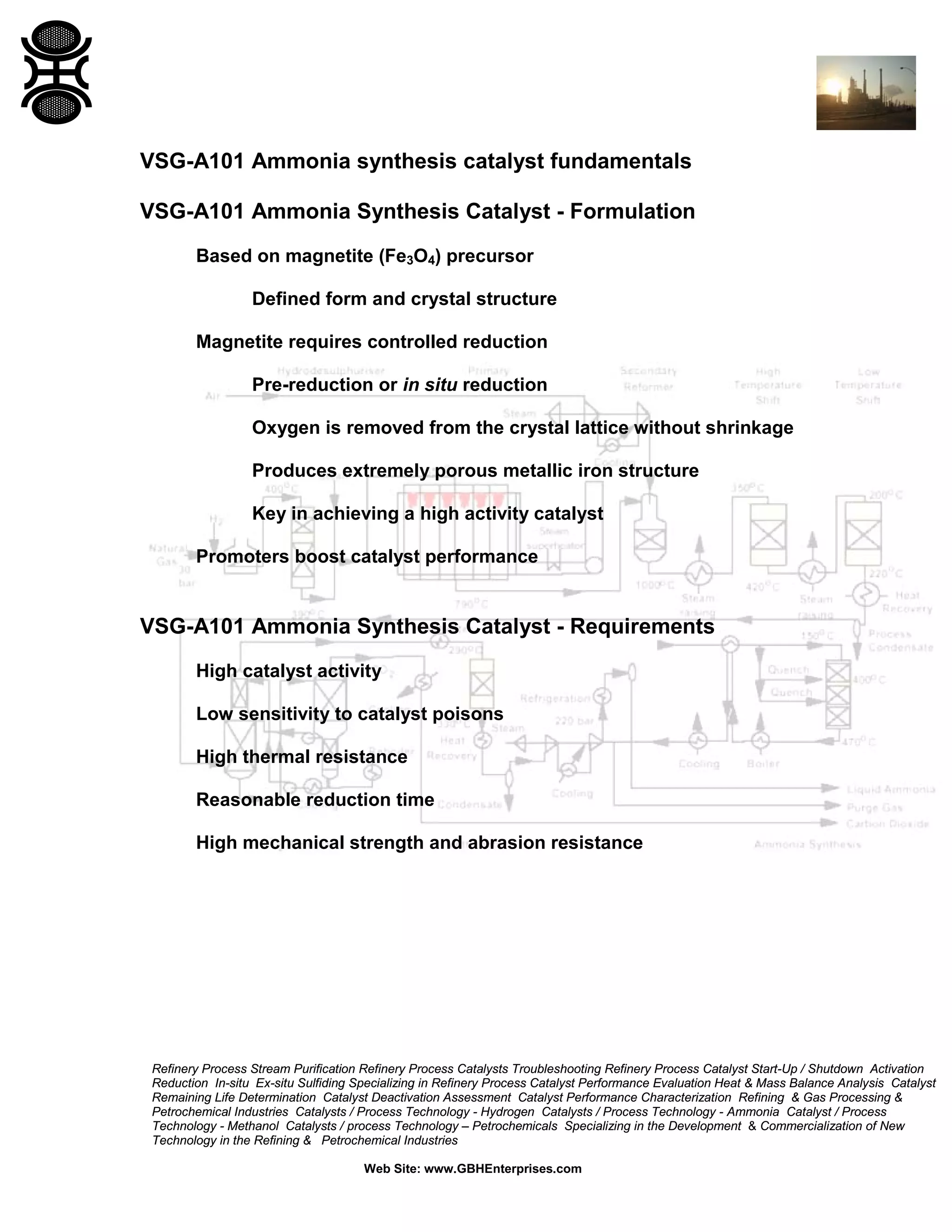
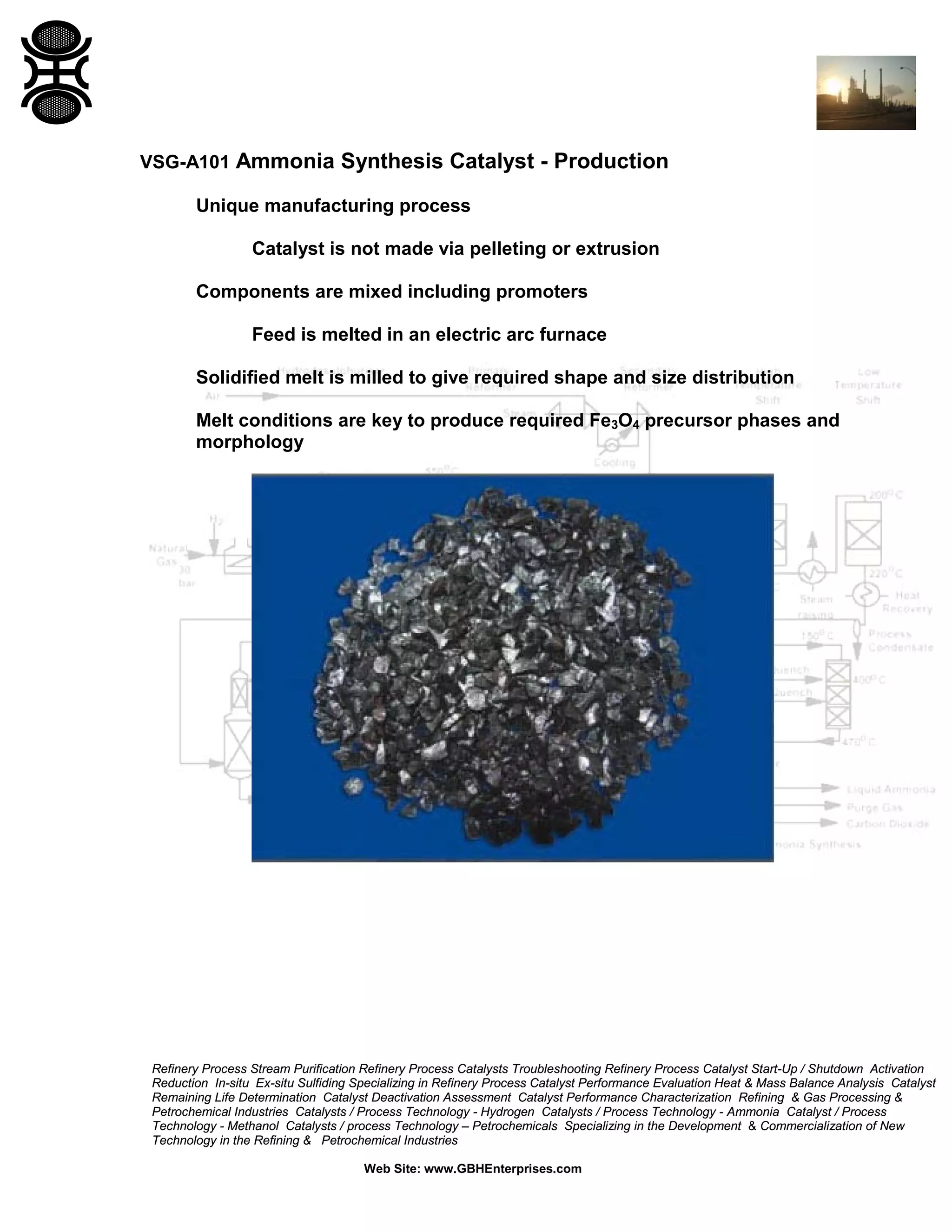
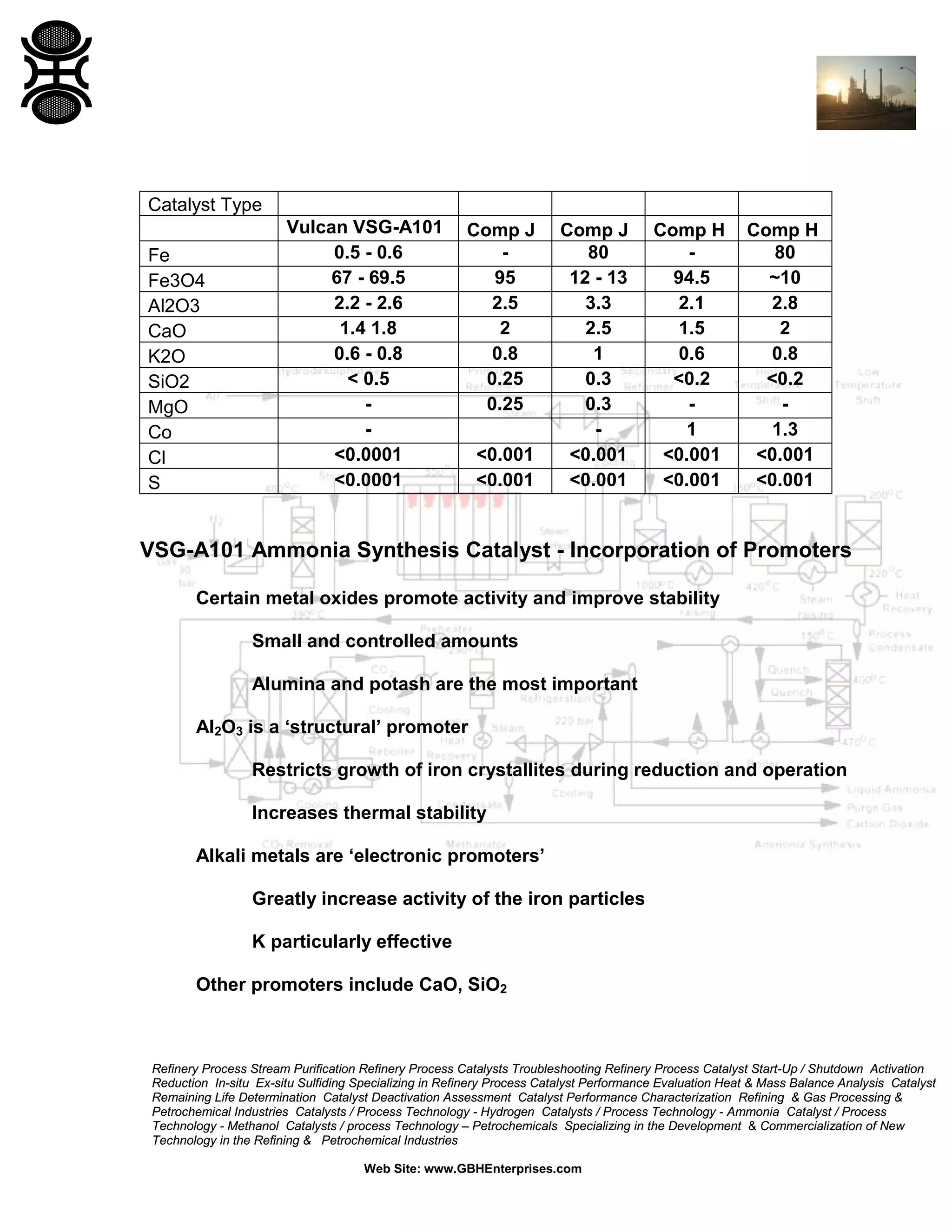
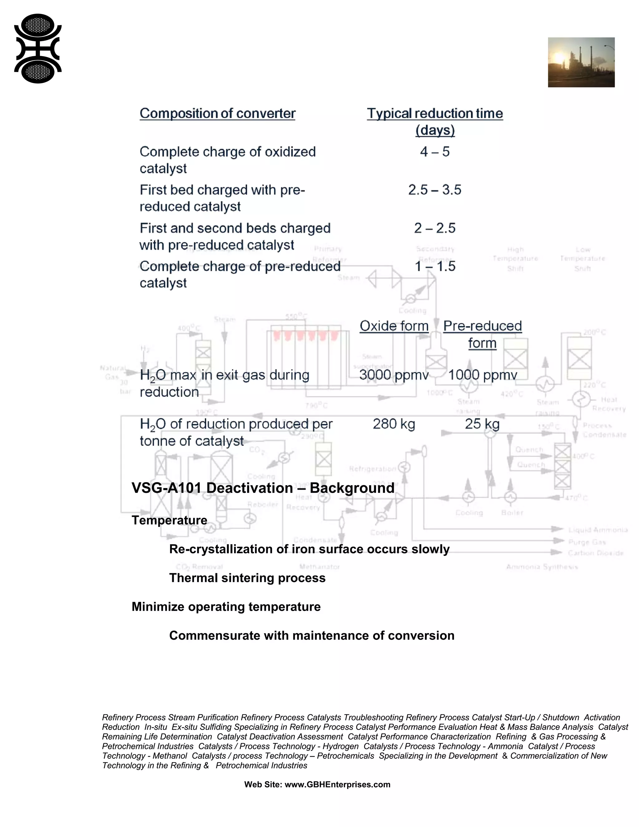

The document discusses ammonia synthesis catalysts including their formulation, production, and operation. Key points include: 1) Ammonia synthesis catalysts are typically based on magnetite that is reduced to form a porous iron structure. Promoters like alumina and potash boost activity and stability. 2) Catalyst production involves melting components to control precursor phases before milling to size. 3) The reaction favors high pressure and low temperature. Typical conditions are 350-530°C and 100-600 bar. Temperature and pressure balance kinetics and equilibrium.


![Natural Gas to Olefins final.[1]](https://cdn.slidesharecdn.com/ss_thumbnails/fabcbabc-8195-489e-a01e-9bc7b6460909-150612193514-lva1-app6892-thumbnail.jpg?width=640&height=640&fit=bounds)


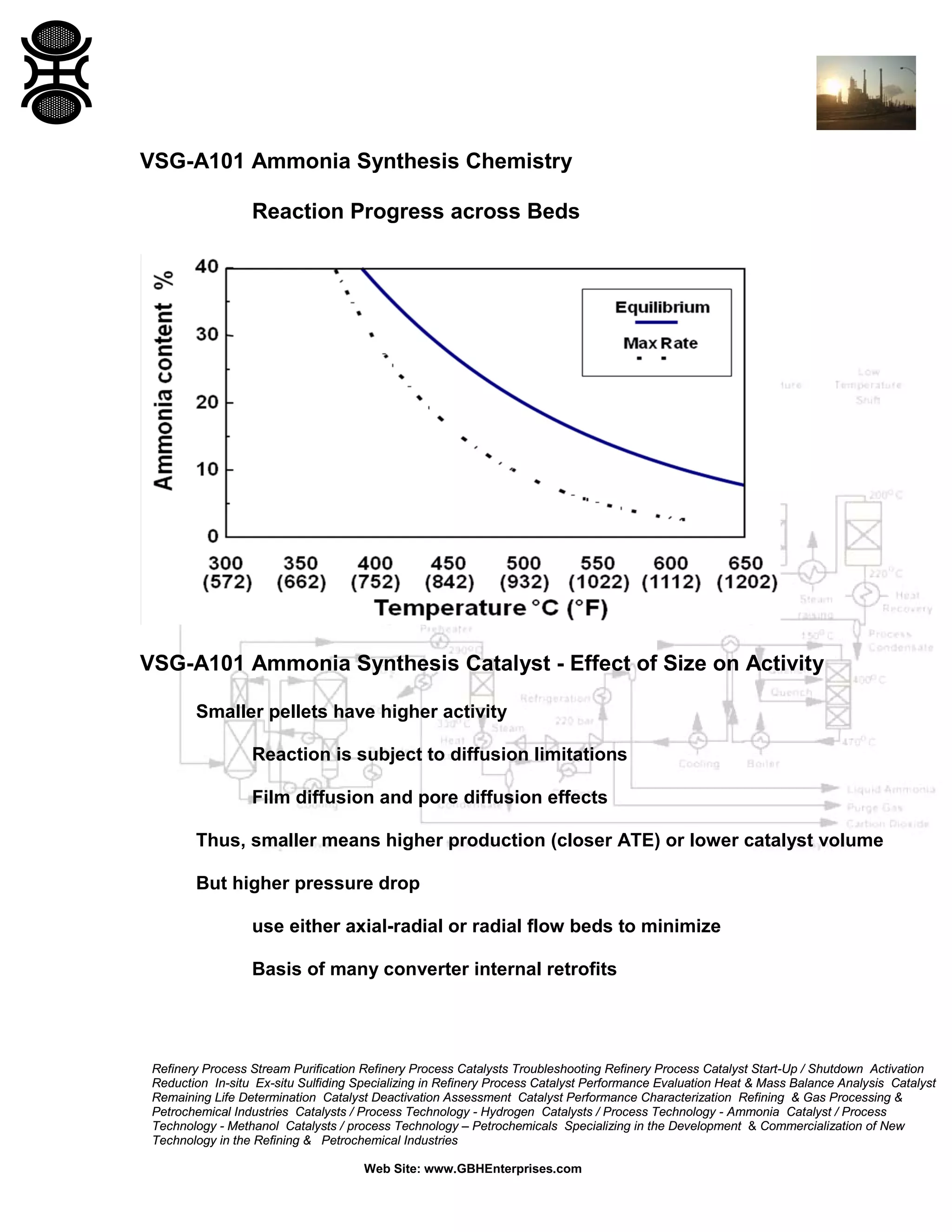
![Vibe Coding vs. Spec-Driven Development [Free Meetup]](https://cdn.slidesharecdn.com/ss_thumbnails/vibecodingvsspecdrivendevelopment-251209105622-43f455e7-thumbnail.jpg?width=640&height=640&fit=bounds)

