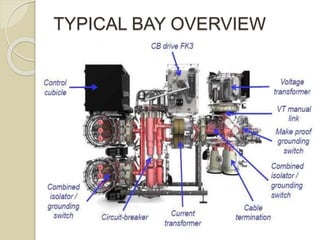
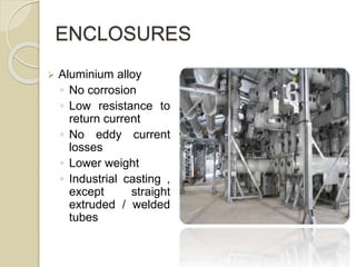
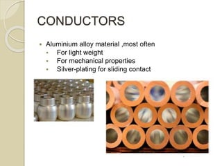
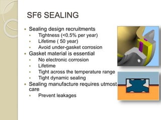
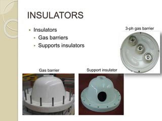
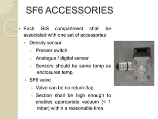
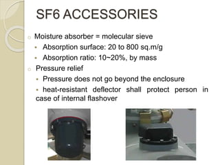
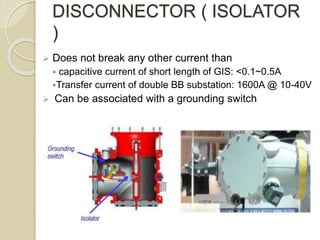
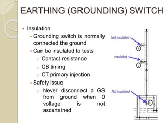
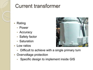
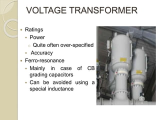
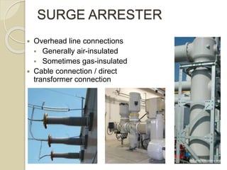
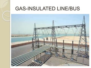
GAS INSULATED SUB-STATION
RONAL PARMAR
140080707003
CONTENTS
 Typical bay overview
 Enclosures
 Conductor
 SF6 sealing
 Insulators
 SF6 accessories
 Circuit Breaker
 Disconnector ( Isolator )
 Earthing ( grounding) switch
 Current transformer
 Voltage transformer
 Surge arrester
 GAS-insulated line / bus
TYPICAL BAY OVERVIEW
ENCLOSURES
 Aluminium alloy
◦ No corrosion
◦ Low resistance to
return current
◦ No eddy current
losses
◦ Lower weight
◦ Industrial casting ,
except straight
extruded / welded
tubes
CONDUCTORS
 Aluminium alloy material ,most often
 For light weight
 For mechanical properties
 Silver-plating for sliding contact
SF6 SEALING
 Sealing design recruitments
 Tightness (<0.5% per year)
 Lifetime ( 50 year)
 Avoid under-gasket corrosion
 Gasket material is essential
 No electronic corrosion
 Lifetime
 Tight across the temperature range
 Tight dynamic sealing
 Sealing manufacture requires utmost
care
 Prevent leakages
INSULATORS
 Insulators
 Gas barriers
 Supports insulators
3-ph gas barrier
Support insulatorGas barrier
SF6 ACCESSORIES
 Each GIS compartment shall be
associated with one set of accessories
 Density sensor
o Presser switch
o Analogue / digital sensor
o Sensors should be same temp as
enclosures temp.
 SF6 valve
o Valve can be no return /tap
o Section shall be high enough to
enables appropriate vacuum (< 1
mbar) within a reasonable time
o Moisture absorber = molecular sieve
 Absorption surface: 20 to 800 sq.m/g
 Absorption ratio: 10~20%, by mass
o Pressure relief
 Pressure does not go beyond the enclosure
 heat-resistant deflector shall protect person in
case of internal flashover
SF6 ACCESSORIES
CIRCUIT-BREAKER
 Main sub-station item
 grading capacitors in case of several breaks per
pole
 Tested at 10,000 close/open cycles
CIRCUIT-BREAKER DRIVE
 Different types
 Spring drive with no
driving fluid
 Hydraulic drive
 gas storage
 Spring storage
 Pneumatic drives
 Out-dated
 Need of water draining
 No move when CB is
not operated, while
hydraulic and
pneumatic
mechanisms daily
require several pump
starts for pressure
topping up
 Stable timing,
insensitiveness to
temperature and
pressure, ideal for
POW(point of wave)
switching.
CIRCUIT-BREAKER DRIVE
DISCONNECTOR ( ISOLATOR
)
 Does not break any other current than
 capacitive current of short length of GIS: <0.1~0.5A
Transfer current of double BB substation: 1600A @ 10-40V
 Can be associated with a grounding switch
EARTHING (GROUNDING) SWITCH
 Insulation
 Grounding switch is normally
connected the ground
 Can be insulated to tests
o Contact resistance
o CB timing
o CT primary injection
 Safety issue
o Never disconnect a GS
from ground when 0
voltage is not
ascertained
Current transformer
 Rating
 Power
 Accuracy
 Safety factor
 Saturation
 Low ratios
 Difficult to achieve with a single primary turn
 Overvoltage protection
 Specific design to implement inside GIS
VOLTAGE TRANSFORMER
 Ratings
 Power
o Quite often over-specified
 Accuracy
 Ferro-resonance
 Mainly in case of CB
grading capacitors
 Can be avoided using a
special inductance
SURGE ARRESTER
 Overhead line connections
 Generally air-insulated
 Sometimes gas-insulated
 Cable connection / direct
transformer connection
GAS-INSULATED LINE/BUS
FURTHER PRESENTATION WORK
 Construction of low & medium voltage GIS sub-station
 Construction of high voltage GIS sub-station
 Maintenance of GIS sub-station
 GIS approach in the GRID
 Visit of 400/220KV GIS substation located at DASTAN
, bardoli .
REFERENCES
 Jean-Louis Habert , ” GIS substation design and
execution for HV and EHV application “ , IEEE ,
04/2014
Gas insulated sub station 2

Gas insulated sub station 2

  • 1.
  • 2.
    CONTENTS  Typical bayoverview  Enclosures  Conductor  SF6 sealing  Insulators  SF6 accessories  Circuit Breaker  Disconnector ( Isolator )  Earthing ( grounding) switch  Current transformer  Voltage transformer  Surge arrester  GAS-insulated line / bus
  • 3.
  • 4.
    ENCLOSURES  Aluminium alloy ◦No corrosion ◦ Low resistance to return current ◦ No eddy current losses ◦ Lower weight ◦ Industrial casting , except straight extruded / welded tubes
  • 5.
    CONDUCTORS  Aluminium alloymaterial ,most often  For light weight  For mechanical properties  Silver-plating for sliding contact
  • 6.
    SF6 SEALING  Sealingdesign recruitments  Tightness (<0.5% per year)  Lifetime ( 50 year)  Avoid under-gasket corrosion  Gasket material is essential  No electronic corrosion  Lifetime  Tight across the temperature range  Tight dynamic sealing  Sealing manufacture requires utmost care  Prevent leakages
  • 7.
    INSULATORS  Insulators  Gasbarriers  Supports insulators 3-ph gas barrier Support insulatorGas barrier
  • 8.
    SF6 ACCESSORIES  EachGIS compartment shall be associated with one set of accessories  Density sensor o Presser switch o Analogue / digital sensor o Sensors should be same temp as enclosures temp.  SF6 valve o Valve can be no return /tap o Section shall be high enough to enables appropriate vacuum (< 1 mbar) within a reasonable time
  • 9.
    o Moisture absorber= molecular sieve  Absorption surface: 20 to 800 sq.m/g  Absorption ratio: 10~20%, by mass o Pressure relief  Pressure does not go beyond the enclosure  heat-resistant deflector shall protect person in case of internal flashover SF6 ACCESSORIES
  • 10.
    CIRCUIT-BREAKER  Main sub-stationitem  grading capacitors in case of several breaks per pole  Tested at 10,000 close/open cycles
  • 11.
    CIRCUIT-BREAKER DRIVE  Differenttypes  Spring drive with no driving fluid  Hydraulic drive  gas storage  Spring storage  Pneumatic drives  Out-dated  Need of water draining
  • 12.
     No movewhen CB is not operated, while hydraulic and pneumatic mechanisms daily require several pump starts for pressure topping up  Stable timing, insensitiveness to temperature and pressure, ideal for POW(point of wave) switching. CIRCUIT-BREAKER DRIVE
  • 13.
    DISCONNECTOR ( ISOLATOR ) Does not break any other current than  capacitive current of short length of GIS: <0.1~0.5A Transfer current of double BB substation: 1600A @ 10-40V  Can be associated with a grounding switch
  • 14.
    EARTHING (GROUNDING) SWITCH Insulation  Grounding switch is normally connected the ground  Can be insulated to tests o Contact resistance o CB timing o CT primary injection  Safety issue o Never disconnect a GS from ground when 0 voltage is not ascertained
  • 15.
    Current transformer  Rating Power  Accuracy  Safety factor  Saturation  Low ratios  Difficult to achieve with a single primary turn  Overvoltage protection  Specific design to implement inside GIS
  • 16.
    VOLTAGE TRANSFORMER  Ratings Power o Quite often over-specified  Accuracy  Ferro-resonance  Mainly in case of CB grading capacitors  Can be avoided using a special inductance
  • 17.
    SURGE ARRESTER  Overheadline connections  Generally air-insulated  Sometimes gas-insulated  Cable connection / direct transformer connection
  • 18.
  • 19.
    FURTHER PRESENTATION WORK Construction of low & medium voltage GIS sub-station  Construction of high voltage GIS sub-station  Maintenance of GIS sub-station  GIS approach in the GRID  Visit of 400/220KV GIS substation located at DASTAN , bardoli .
  • 20.
    REFERENCES  Jean-Louis Habert, ” GIS substation design and execution for HV and EHV application “ , IEEE , 04/2014