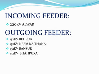
A PRESENTATION
on
SUMMER PRACTICAL TRAINING
at
220 KV GRID SUB STATION KOTPUTLI JAIPUR
Submitted to:-
Dr. Nitin Gupta
Dr. Satyanarayana Neeli
Dept. of Electrical Engineering
Submitted by:-
Sunil Kumar Yadav
ID- 2013UEE1176
Batch- E1
Malaviya National Institute of Technology, Jaipur
INTRODUCTION
In India Electrical power is Generated at a voltage of 11kv
to 33kv ,which is taken stepped up to the transmission
level in the range of 66kv to 765kv.
Substation is an assembly of apparatus ,which transform
one voltage level to another level. hence a substation is
an Intermediate link between the Generating station and
consumer.
220KV GRID SUBSTATION KOTPUTLI
Operates under RAJASTHAN RAJYA VIDYUT
PRASARAN NIGAM LIMITED
(Department Of Energy, Government Of Rajasthan)
220kv GSS is a conventional, hybrid substation.
It is part of transmission system.
For communication purpose PLCC(Power Line Carrier
Communication) is used.
Voltage is Transformed High(220/132) to Low(132/33)
using Transformer.
220KV GRID SUBSTATION KOTPUTLI
It is divided into two sections:-
A. Panel Section
 Control Panel Section
 Relay and Protection Panel Section
B. Switch Yard
 220kV Section
 132kV Section
Fig.1 – 220 KV GSS ,KOTPUTLI JAIPUR
Substations have switching, protection and control equipment and one
or more transformers. In a large substation, circuit breaker are used to
interrupt any short-circuits or overload currents that may occur on the
network
CONTENTS:-
 SINGLE LINE DIAGRAM
 LIGHTNING ARRESTOR.
 INSULATER.
 POWER TRANSFORMER.
 CURRENT TRANSFOMER.
 CIRCUIT BREAKER.
 BUSBARS.
 PROTECTIVE RELAY.
 CONTROL PANEL.
 POTENTIAL TRANSFORMER
 WAVE TRAP.
 CONCLUSION
INCOMING FEEDER:
 220KV ALWAR
OUTGOING FEEDER:
 132KV BEHROR
 132KV NEEM KA THANA
 132KV BANSUR
 132KV SHAHPURA
OUTGOING FEEDER:
33KV FEEDER:
 PAOTA
 PANIYALA
 PANASIEA
 PATTAN CHALLA
 KOTPUTLI
 BEHROR II
 S. CEMENT
 PUTLI
LIGHTNING ARRESTOR
 Lightning arrestor provide protection to all the
equipment against the HV.an electric discharge
between cloud and earth , known as lightning.
 It is provide to safety transmission & distribution
line.
INSULATER
An electrical insulator
is a material whose
internal electric charge
do not flow freely and
therefor make it very
hard to conduct an
electric current under
the influence of an
electric field.
POWER TRANSFORMER
•For stepping down the system voltage, power transformers are used in
the substations.
• Ratings-
 220/132 kV, 100 MVA
 132/33 kV, 20-25 MVA
• Cooling
• Silica gel breather
• Relays
• Tap changer
CURRENT TRANSFORMER
The current
transformer are used to
stepped down primary
current.
It is used to
measurement/control/
protection.
CIRCUIT BREAKER
 Circuit breaker are used for
switching and protection.
 Brake a circuit automatically
under fault condition.
 A circuit breaker consist of
fixed and moving contact
called electrode under
normal condition.
ISOLATORS
• Used for completely DE-ENERGISE the electrical circuit for SERVICE or
MAINTENANCE.
• Separate the circuit at NO LOAD CONDITION.
BUSBARS
 Bus bars are common
electrical component
through which a
large no. of feeders
operating at some
voltage have to
connected.
 It is used to connect
to transmission line
which go to
electricity.
 It is used to high
material, hollow pipe
conductor.
PROTECTIVE REALAY
 A Protective relay is a device which detect the
fault.
 It is to detect after their go to command
circuit breaker
 It is provide to safety in electrical equipments.
CAPACITIVE VOLTAGE TRANSFORMER
Step down extra high voltage signals.
Provide a low voltage signal.
for MEASUREMENT and COMMUNICATION
to operate a protective relay.
POTENTIAL TRANSFORMER
The potential transformer is used to step down voltage
for measurement purpose.
Rating- 132kV/(110/√3) V
WAVE TRAP (PLCC)
POWER LINE CARRIER COMMUNICATION
Exchange of data and transfer of messages between substations.
WAVE TRAP - TRAPPING the unwanted waves.
CONTROL PANEL
CONTROL PANEL
 It contains Meters, Relays, Recorder and Control
Switches.
 All measurement and control signal come to control
panel from yard for operation.
CONCLUSION
 An Engineer need to have not just theoretical but
practical as well as and so every student is supposed to
undergo a practical training .session after 3rd year
where I have impaired the knowledge about
transmission ,distribution .during the 45 days training
session. we have acquainted with the repairing of a
transformer and testing of transformer. At last is
would like to say that practical training taken at 220kv
GSS Kotputli has broadened my knowledge and
widened my thinking as a professional.
ANY QUERY?

My training

  • 1.
    A PRESENTATION on SUMMER PRACTICALTRAINING at 220 KV GRID SUB STATION KOTPUTLI JAIPUR Submitted to:- Dr. Nitin Gupta Dr. Satyanarayana Neeli Dept. of Electrical Engineering Submitted by:- Sunil Kumar Yadav ID- 2013UEE1176 Batch- E1 Malaviya National Institute of Technology, Jaipur
  • 2.
    INTRODUCTION In India Electricalpower is Generated at a voltage of 11kv to 33kv ,which is taken stepped up to the transmission level in the range of 66kv to 765kv. Substation is an assembly of apparatus ,which transform one voltage level to another level. hence a substation is an Intermediate link between the Generating station and consumer.
  • 3.
    220KV GRID SUBSTATIONKOTPUTLI Operates under RAJASTHAN RAJYA VIDYUT PRASARAN NIGAM LIMITED (Department Of Energy, Government Of Rajasthan) 220kv GSS is a conventional, hybrid substation. It is part of transmission system. For communication purpose PLCC(Power Line Carrier Communication) is used. Voltage is Transformed High(220/132) to Low(132/33) using Transformer.
  • 4.
    220KV GRID SUBSTATIONKOTPUTLI It is divided into two sections:- A. Panel Section  Control Panel Section  Relay and Protection Panel Section B. Switch Yard  220kV Section  132kV Section
  • 5.
    Fig.1 – 220KV GSS ,KOTPUTLI JAIPUR Substations have switching, protection and control equipment and one or more transformers. In a large substation, circuit breaker are used to interrupt any short-circuits or overload currents that may occur on the network
  • 6.
    CONTENTS:-  SINGLE LINEDIAGRAM  LIGHTNING ARRESTOR.  INSULATER.  POWER TRANSFORMER.  CURRENT TRANSFOMER.  CIRCUIT BREAKER.  BUSBARS.  PROTECTIVE RELAY.  CONTROL PANEL.  POTENTIAL TRANSFORMER  WAVE TRAP.  CONCLUSION
  • 8.
    INCOMING FEEDER:  220KVALWAR OUTGOING FEEDER:  132KV BEHROR  132KV NEEM KA THANA  132KV BANSUR  132KV SHAHPURA
  • 9.
    OUTGOING FEEDER: 33KV FEEDER: PAOTA  PANIYALA  PANASIEA  PATTAN CHALLA  KOTPUTLI  BEHROR II  S. CEMENT  PUTLI
  • 10.
    LIGHTNING ARRESTOR  Lightningarrestor provide protection to all the equipment against the HV.an electric discharge between cloud and earth , known as lightning.  It is provide to safety transmission & distribution line.
  • 11.
    INSULATER An electrical insulator isa material whose internal electric charge do not flow freely and therefor make it very hard to conduct an electric current under the influence of an electric field.
  • 12.
    POWER TRANSFORMER •For steppingdown the system voltage, power transformers are used in the substations. • Ratings-  220/132 kV, 100 MVA  132/33 kV, 20-25 MVA • Cooling • Silica gel breather • Relays • Tap changer
  • 13.
    CURRENT TRANSFORMER The current transformerare used to stepped down primary current. It is used to measurement/control/ protection.
  • 14.
    CIRCUIT BREAKER  Circuitbreaker are used for switching and protection.  Brake a circuit automatically under fault condition.  A circuit breaker consist of fixed and moving contact called electrode under normal condition.
  • 15.
    ISOLATORS • Used forcompletely DE-ENERGISE the electrical circuit for SERVICE or MAINTENANCE. • Separate the circuit at NO LOAD CONDITION.
  • 16.
    BUSBARS  Bus barsare common electrical component through which a large no. of feeders operating at some voltage have to connected.  It is used to connect to transmission line which go to electricity.  It is used to high material, hollow pipe conductor.
  • 17.
    PROTECTIVE REALAY  AProtective relay is a device which detect the fault.  It is to detect after their go to command circuit breaker  It is provide to safety in electrical equipments.
  • 18.
    CAPACITIVE VOLTAGE TRANSFORMER Stepdown extra high voltage signals. Provide a low voltage signal. for MEASUREMENT and COMMUNICATION to operate a protective relay.
  • 19.
    POTENTIAL TRANSFORMER The potentialtransformer is used to step down voltage for measurement purpose. Rating- 132kV/(110/√3) V
  • 20.
    WAVE TRAP (PLCC) POWERLINE CARRIER COMMUNICATION Exchange of data and transfer of messages between substations. WAVE TRAP - TRAPPING the unwanted waves.
  • 21.
  • 22.
    CONTROL PANEL  Itcontains Meters, Relays, Recorder and Control Switches.  All measurement and control signal come to control panel from yard for operation.
  • 23.
    CONCLUSION  An Engineerneed to have not just theoretical but practical as well as and so every student is supposed to undergo a practical training .session after 3rd year where I have impaired the knowledge about transmission ,distribution .during the 45 days training session. we have acquainted with the repairing of a transformer and testing of transformer. At last is would like to say that practical training taken at 220kv GSS Kotputli has broadened my knowledge and widened my thinking as a professional.
  • 24.