This document discusses alternative lightweight materials and manufacturing technologies for vehicle frontal bumper beams. Three composite materials - GMT, GMTex, and GMT-UD - were characterized and evaluated through testing for their potential use in bumper beams. Quasi-static tensile, compression, and impact tests were conducted to determine the materials' mechanical properties and impact performance. Finite element analysis was also used to simulate impact loading and compare the performance of the composite materials to existing steel solutions. The results indicate the composite materials, especially GMT-UD, could provide advantages over steel in energy absorption and weight reduction while maintaining sufficient strength and stiffness for the bumper beam application.
![Alternative lightweight materials and component manufacturing
technologies for vehicle frontal bumper beam
G. Belingardi a
, A.T. Beyene a
, E.G. Koricho b,⇑
, B. Martorana c
a
Politecnico di Torino, Department of Mechanical and Aerospace Engineering, Italy
b
Michigan State University, Composite Vehicle Research Center, USA
c
Centro Ricerche FIAT, strada Torino 50, Orbassano Torino, Italy
a r t i c l e i n f o
Article history:
Available online 25 October 2014
Keywords:
Bumper
Crashworthiness
Lightweight design
Composite structures
Optimization
a b s t r a c t
One of the vehicle subsystem where large advantage is expected in lightweight design is the bumper sub-
systems. Bumper subsystems are designed to prevent or reduce physical damage to the front or rear ends
of passenger motor vehicles during collusion.
In this paper, detail design aspects and method of analysis with particular reference to the application
of composite materials to automotive front bumper subsystem, crash box and bumper beam. Innovative
design of integrated crash box and bumper beam has been considered for better crashworthiness; the
proposed solution results to be of great interest also from the points of view of subassembly cost and
effective production process.
Three materials have been characterized under quasi static and impact tests for this bumper beam
application: GMT, GMTex, and GMT-UD. Major parameters, such as impact energy, peak load, crash resis-
tance, energy absorption and stiffness have been taken as evaluation criteria to compare the proposed
materials solutions with pultruded and steel solutions. Finally, the results predicted by the finite element
analysis have been evaluated and interpreted in comparison with other existing solutions to put in
evidence the effectiveness of the proposed innovative materials and design concept solutions.
Ó 2014 Elsevier Ltd. All rights reserved.
1. Introduction
Automobile bumper subsystem is the frontal and rear structure
of the vehicle that has the purpose of energy absorption during low
velocity impact. Usually, bumper subsystem consists of bumper
transverse beam, stays, impact-absorbing materials (such as foam
or honeycomb) connected to the structural components (generally
the bumper beam) and a cover, that has both aesthetic and protec-
tion purposes. Among those elements, the bumper beam is the
main structural component; it is expected to be deformable
enough to absorb the impact energy, in order to reduce the risks
of injury for pedestrians and other vulnerable road users, but, at
the same time, it should also have sufficient strength and stiffness
to give place to small intrusion of the engine compartment and,
therefore, to protect the nearby vehicle components.
Composite materials are characterized by high specific strength,
both in static and impact loading conditions, and high specific stiff-
ness; they could be an interesting candidate material for this type
of component, posing as targets the lightweight together with the
maintenance of at least the same level of safety performance in
comparison with the present steel solution.
When designing with composite material, it is always needed
not only to choice the appropriate material but to think composite
(i.e. to not simply replace the metallic material with the new one,
but to redesign the part) and to select the type of production tech-
nology that will be used in manufacturing, as this choice will affect
deeply both the structural performance and the cost and the pro-
duction rate [1]. Therefore material, design and manufacturing
technology are strictly linked each other and should be considered
all together.
From the point of view of manufacturing technology we have
taken into consideration two different types: pultrusion and die
forming. Both of them are cost-effective and fully automated and
give high quality parts in terms of geometry accuracy and degree
of consistency of mechanical property (mainly due to process
automation).
Pultrusion has a number of advantages such as perfect fiber
alignment and high fiber volume since polymerization takes place
while the fiber is under tension, capable of producing both closed
and open section with a variety of end profiles, etc. However, at
the moment the technology is strongly limited to straight and
http://dx.doi.org/10.1016/j.compstruct.2014.10.007
0263-8223/Ó 2014 Elsevier Ltd. All rights reserved.
⇑ Corresponding author.
E-mail address: koricho@msu.edu (E.G. Koricho).
Composite Structures 120 (2015) 483–495
Contents lists available at ScienceDirect
Composite Structures
journal homepage: www.elsevier.com/locate/compstruct](https://image.slidesharecdn.com/j-210913145700/75/J-compstruct-2014-10-007-1-2048.jpg)
![constant section. Conversely, die forming composite manufactur-
ing technology has also its own advantages, i.e. it allows producing
structurally integrated crash box and beam, as shown in Fig. 1, that
improve both manufacturing and assembling rate and eliminate
connection between bumper beam and crash box. However, it is
mainly limited to open section profiles that are generally less per-
forming than the closed section profiles.
As the targeted component is designed for impact loading, prior
to conduct numerical impact analysis at the component level, the
impact performance of composite material are assessed. In general,
impact responses and damage mechanisms for the whole group of
composite materials are more complex comparing with the con-
ventional metallic materials and depend on a number of different
parameters: fiber and matrix type, section shape and dimensions,
impact velocity, impact angle, shape of striker, target geometry
and target material. Open literatures show that a composite tube
is capable of absorbing significant impact energy by material frag-
mentation and large changes in the tubes cross-sectional geometry
when the tube undergoes large flexural deformation [2–7].
In the current study six material were considered. For pultruded
bumper beam solution, unidirectional pultruded E Glass/epoxy, a
bidirectional fabric E Glass/epoxy and steel material were com-
pared. The detailed mechanical properties documented [8]. For
the case of die formed integrated crash box–beam solution, three
materials were considered:
A classic glass-mat-reinforced thermoplastics (GMT) i.e. an end-
less fiber glass mate reinforced PP with randomly oriented glass
fibers,
GMTex, i.e. a chopped fiber glass mat reinforced PP laminate
with randomly oriented glass fibers and additionally reinforced
with a fabric inside and
GMT-UD, i.e. a chopped fiber glass mat reinforced PP laminate
with randomly oriented glass fibers and additionally reinforced
with unidirectional oriented glass fiber layers.
These three materials, supplied by Quadrant, were considered
for front bumper application. Considering the novelty of the
modified material, extensive material characterization had been
conducted to obtain the main mechanical properties of the mate-
rial and to understand the failure mechanism for the intended
loading case and finally their capability for substituting the current
steel material were numerically assessed.
2. Material characterization
The composite materials were characterized under a tensile
(both longitudinal and transverse direction), compressive (both
longitudinal and transverse direction), and a drop-dart tests. A
brief summary of the test set-up and of the obtained mechanical
characteristics of the tested materials are presented in the follow-
ing sections.
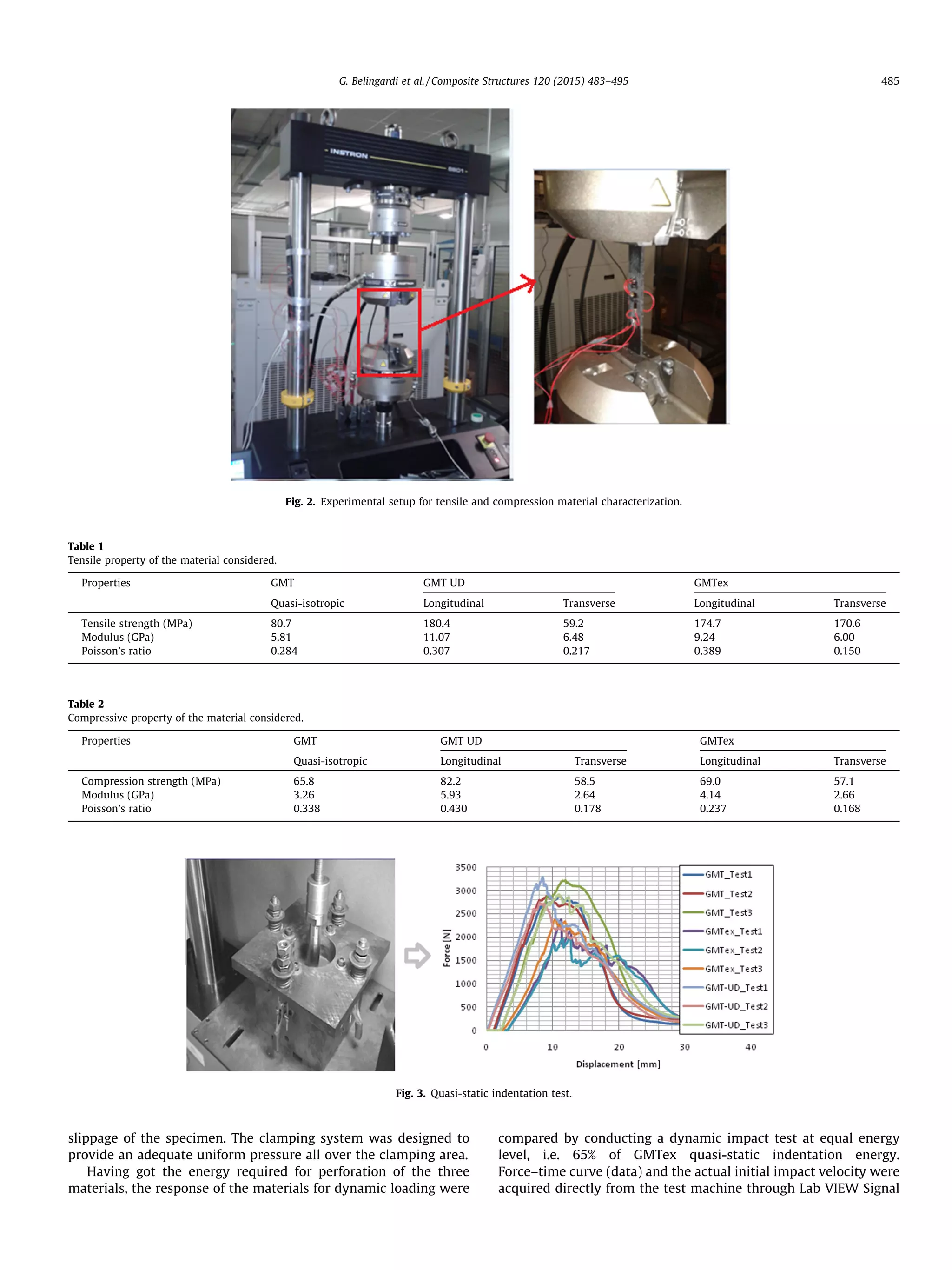
2.1. Experimental setup for tensile test
Five specimens for each material type, in both longitudinal and
transverse directions, were tested under tensile loading with a
100 kN capacity servo-hydraulic testing machine (INSTRON-
8801), as shown in Fig. 2. Each specimen was clamped by means
of hydraulic wedge grips. The machine was equipped with a stan-
dard load cell and a crosshead displacement measuring device.
During the mount phase of the specimen, the maximum preload
was controlled and set lower than 0.2 kN in order to avoid
specimen damage. According to ASTM D3039, specimens were
subjected to monotonic tensile loading with a stroke rate of
2 mm/min. The specimens were instrumented by strain gages to
measure Young’s modulus and Poisson’s ratio. To acquire the strain
gages data, a NI WLS-9163 data acquisition board was used and to
acquire load and crosshead displacement data from the machine, a
NI DAQCard-6062E was utilized. All data were acquired with a
sampling rate equal to 1 kHz. The main mechanical properties
are reported in Table 1.
2.2. Experimental setup for compression test
Similarly, five specimens for each material, in both longitudinal
and transverse directions, were tested under compressive loading
as per ASTM D6641/D6641M and the found experimental results
are presented in Table 2.
2.3. Experimental setup for the drop dart test
Prior to impact test, quasi-static indentation tests were
performed on Zweck Roell 100 universal testing machine, to inves-
tigate perforation energy of the proposed composite laminates,
Fig. 3. Main results are reported in Table 3.
Experimental impact tests were performed according to ASTM
standard 3029 using an instrumented free-fall drop dart testing
machine. The impactor has a carriage mass of 5.735 kg and an
hemispherical head with a radius of 10 mm and the maximum
falling height of the testing machine is 2 m (see Fig. 4). The drop-
weight apparatus was equipped with a motorized lifting track.
The collected data were stored after each impact and the impactor
was returned to its original starting height. Using this technique,
the chosen impact velocity was consistently obtained in successive
impacts. By means of a piezoelectric load cell, force–time curves
were acquired and, with a double integration of acceleration–time
curve, force–displacement curves were obtained. Square specimen
panels, with 100 mm edge, were clamped in the specimen holder
with a 76.2 mm inner diameter, and fixed to a rigid base to prevent
Fig. 1. Integrated composite solution developed by Quadrant Plastic Composites International (a) and used on Mercedes for top class vehicle (b).
484 G. Belingardi et al. / Composite Structures 120 (2015) 483–495](https://image.slidesharecdn.com/j-210913145700/75/J-compstruct-2014-10-007-2-2048.jpg)
![express environment developed for this particular test scenario
and the other important dynamic variables were calculated using
free body motion equation [12] as described in Fig. 5.
2.4. Impact response of composite material
Representative curves of Force vs. time, Energy vs. time and pic-
tures of the damage mode, respectively for the first and perforation
impacts, are presented in Figs. 6 and 8. The number of impacts
needed to perforate the plate and the damage development
through the successive impacts was monitored by impacting a vir-
gin specimen every time to the desired number of impacts. Figs. 7
and 9 are presenting pictures of the impacted surfaces of the
specimen according to the specified number of impacts, respec-
tively for the GMT and GMT-UD materials. A smooth Force vs. time
and the relatively lower absorbed energy of GMT-UD at the first
impact can be linked to the observation that the GMT-UD plate
has no visible damage, as shown in Fig. 6e. This implies that most
of the energy was dissipated due to mechanisms other than mate-
rial internal fracture. Whereas, Force vs. time curve of both GMT
and GMTex shows an apex that can be interpreted as a sign of frac-
ture and this can be linked to the visible damages that can be
observed on the impacted plate shown in Fig. 6c and d.
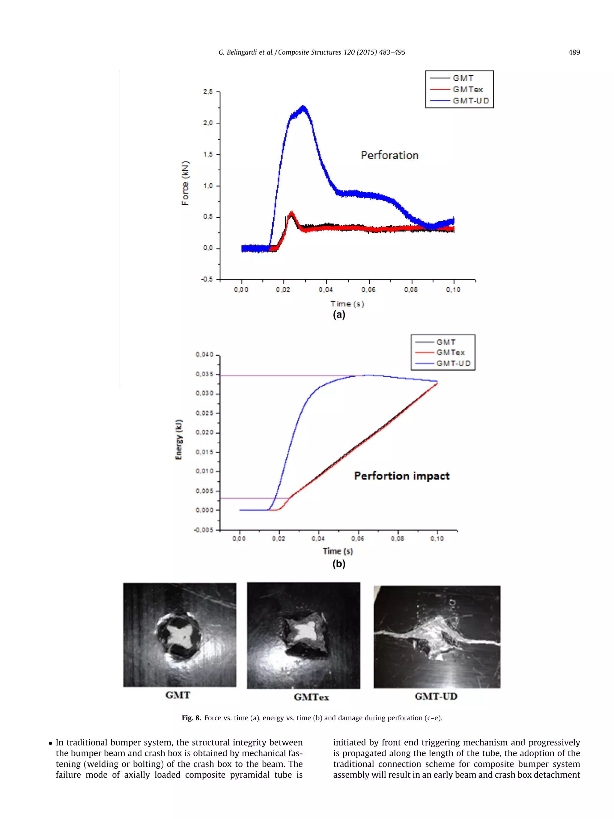
Fig. 8 shows some results at the perforation after repeated
impacts. We can observe that at perforation, GMT and GMTex have
similar failure behavior i.e. the impactor penetrates the plate dam-
aging a confined area around the perforation hole but without
extensive crack propagation into the plate (see Fig. 8c and d). This
is due to the fact that classical GMT has in plane quasi-isotropic
properties, i.e. it has almost uniform continues fibers in all direc-
tion, and this prevented the cracks at the edge of the perforation
central hole from being propagated. Similarly, GMTex has a fabric
ply at the midplane of classical GMT, therefore the crack propaga-
tion has been impeded by the joint effects of the random and fabric
fibers perpendicular to the crack. Conversely, in the case of GMT-
UD, being the classical GMT reinforced by unidirectional fibers,
there was a chance for a crack originated at from the edge of the
perforation central hole to propagate along the fiber direction
(see Fig. 8e).
It is well known that, composite material has poor plastic
properties, therefore, when energy absorbing components, like
bumper beam, are designed using materials of this type, the
energy dissipation can mainly take place through the material
fracturation. Therefore the more the component material is frag-
mented the larger amount of energy is dissipated. In this respect,
Energy vs. time curve and the damage mode of GMT-UD at perfo-
ration impact show a better fracture behavior – i.e. in addition to
the impactor penetration through the plate thickness, crack prop-
agate along the plate width which increases the amount of energy
absorption.
3. Bumper beam design
As indicated in the introductive paragraph, two different types
of manufacturing technology, namely pultrusion and die forming,
have been considered to manufacture the beam with the desired
shape. Both of them are cost-effective and fully automated manu-
facturing technologies and give high quality parts in terms of
geometry accuracy and degree of consistency of mechanical prop-
erty. Pultrusion manufacturing solution is very effective to make a
great variety of end profiles but is currently limited to straight
beams, moreover is not suitable to develop integrated crash box–
beam solutions. Die forming manufacturing technology is suitable
to develop integrated crash box–beam solution and with no limita-
tion on the beam curvature, but it is limited to open section pro-
files, that are structurally weaker than the closed section profiles,
and has limitations on the shape of the section profiles.
Fig. 10, shows a simplified model of pultruded bumper beam (a)
and die formed GMT/GMTex integrated cashbox-beam bumper
beam (b) considered for a nonlinear finite element simulation
using commercial code ABAQUS/Explicit version 6.12-1. In both
cases, the rigid bodies were modeled as discrete rigid surfaces in
order to create higher mesh density at critical contact areas. A
mass of 1000 kg was rigidly coupled with the two rear extremities
of the crash boxes, in order to simulate the vehicle mass. Boundary
condition was also applied on vehicle mass point whose initial
velocities towards the rigid wall were set in turn equal to 4, 8
and 15 km/h, in order to simulate three different impact situations
relevant for the bumper system.
Table 3
Energy for quasi-static perforation test.
Material Plate thickness [mm] Energy [J]
GMT 4 38.9
GMTex 3 31.1
GMT-UD 4 41.2
Fig. 4. Drop dart testing machine and specimen configuration.
Fig. 5. Drop test motion description.
486 G. Belingardi et al. / Composite Structures 120 (2015) 483–495](https://image.slidesharecdn.com/j-210913145700/75/J-compstruct-2014-10-007-4-2048.jpg)
![3.1. E-Glass/epoxy pultruded beam solution
Pultruded beam solution have been studied by a number of
scholars [10,11], for roadside barrier structures which is a similar
to lateral loading case as in vehicle bumper. Roadside barrier are
usually designed to shield motorists from man-made or natural
hazards, to redirect errant vehicles back on to roadway and for
energy dissipation in case crashing. These studies indicated that
pultruded composite materials are viable for use in guardrail sys-
tem due to their pseudo-ductile characteristics that arise primarily
from material fragmentation (crushing, separation and tearing of
composite materials) and large changes in the tubes cross-
sectional geometry when the tube undergoes large flexural
deformation.
The proposed pultruded bumper beam solution [8] intended to
utilize and optimize the pseudo-ductile behavior of pultruded
Fig. 6. Force vs. time (a), energy vs. time (b) and damage at the first impact (c–e).
G. Belingardi et al. / Composite Structures 120 (2015) 483–495 487](https://image.slidesharecdn.com/j-210913145700/75/J-compstruct-2014-10-007-5-2048.jpg)
![composite beam for effective energy dissipation at low velocity
vehicle frontal crash. The pseudo-ductile behavior was optimized
through a structural optimization procedure of the beam section
profile (that can be easily obtained by means of a properly shaped
die section) and of the curvature (that at present is not offered by
main manufacturers with this technology) aimed to obtain a pro-
gressive energy absorption and a stable flexural failure of the com-
posite bumper beam.
A numerical study has been conducted according to the meth-
odology developed in [8,9] in order to explore the possibility of
substituting the current metallic bumper beam with E-Glass/epoxy
pultruded composite beam. The resulting structures are compared
in terms of shape and in terms of energy absorbing capability, com-
parison is also established with steel normal production solution.
The pseudo-ductile behavior of pultruded beams arise from
material fragmentation (crushing, separation and tearing of com-
posite materials) and large changes in the tubes cross-sectional
geometry when the tube undergoes large flexural deformation.
Therefore, the analysis has been conducted based on the hypothe-
sis that a properly optimized and predefined stress concentration
zone – i.e. beam longitudinal groves (through an optimization
process of the end profile shape) – can serve as crash triggering
mechanism, i.e. to initiate cracks formation and to develop pro-
gressive tear along beam longitudinal axis. The optimization has
been conducted using as design variables the number of groves
on the height (h) of the beam end profile and the distribution of
the wall thickness, taking advantage from the capability of the
pultrusion technology to produce such a particular profile. The per-
formance comparison among the proposed end profiles was done
through the investigation of impact event characteristic data, such
as force–time, force–displacement, energy–displacement and
displacement–time curves. The optimized beam section profile is
presented on Fig. 11.
Even if the current pultruded manufacturing technology is
mainly limited to straight beam (curved pultrusion technology is
still in infant stage) an optimization has also been conducted on
beam curvature radius (R) Fig. 12. A large number of beam curva-
ture radius, from straight axis to smaller radius, were considered.
The failure phenomenon and the bumper beam performance were
closely monitored using the already mentioned impact event
characteristic data.
3.2. GMT/GMTex die forming integrated crash box–beam solution
Die forming manufacturing technology is capable of producing
structurally integrated crash box and beam as a single component.
This is an extremely interesting feature of this technology because
it leads to remarkable improvements both from the point of view
of the manufacturing/assembly rate and from the point of view
of a relevant reduction of the number of different components that
should be produced and assembled to construct the front end
structure. Besides, since joining is one of the critical issue in using
composite part in automotive structures (as structures often have
their weak points where their parts are joined together), The die
forming technology is suitable for producing an integrated bumper
beam and crash box structure thus eliminating the need of joints in
between.
A nonlinear finite element simulation, with a simplified bumper
beam model, as shown in Fig. 10b, has been carried out using the
commercial code ABAQUS/Explicit version 6.12-1. The model com-
prises two parts, one rigid part, i.e. the impact rigid wall, and one
deformable part that integrates crash-boxes and transverse beam
and its back cover. The integrated beam solution has been
developed in three alternatives according to the three considered
composite materials, GMT, GMtx and GMT-UD. A mass of
1000 kg is rigidly attached at the two rear extremities of the crash
boxes, in order to simulate the vehicle mass, it moves with an ini-
tial velocity of 4 or 8 km/h towards the rigid wall. Considering the
load path, different sections have been used at different portions of
the proposed structure as shown in Fig. 10b. Hollow tapered trun-
cated square based pyramids were proposed for crash boxes, in
order to obtain a progressive failure.
The design solutions that are using the proposed materials were
developed starting from the normal production solution (that is
the reference solution) made by steel by means of two approaches:
- by direct substitution of the current steel beam, through inte-
gration of the composite beam with crash boxes with minor
modifications to the base plate only for joining purpose, using
the wall thickness recommended by the company i.e. 8 mm,
and
- through equal bending stiffness approach [9], i.e. for a given
thickness and stiffness of the reference material, the thickness
to be adopted with the targeted material can be approximately
calculated by Eq. (1).
hx ¼ hs
ffiffiffiffiffi
Es
Ex
3
s
ð1Þ
where hs and hx are respectively the wall thickness of steel and of
the targeted material solutions and Es and Ex are the elastic modulus
of steel and the targeted material respectively.
During low velocity impact, such as small parking load, the
bumper beam is expected only to bump i.e. it has to operate within
elastic limit without any form of permanent damage. Therefore, for
the current study, the allowable minimum thickness of the bumper
for such small load was determined through monitoring impact
energy curve. Having got the threshold value the thickness, it
was gradually increased up to a value where the beam gives a sim-
ilar impact performance as with the reference material. Finally the
mass reduction has been evaluated.
3.2.1. Design consideration for the integrated bumper beam
When metallic components are substituted by composite com-
ponents, taking into account the very different failure modes of the
two materials, new design hypothesis has to be followed, only in
this way the advantage that comes from the important features
of the new material can be maximized. Therefore, in the current
integrated bumper system the following three design consider-
ations were made:
Fig. 7. Damage development through the successive impact for GMT and GMTex.
488 G. Belingardi et al. / Composite Structures 120 (2015) 483–495](https://image.slidesharecdn.com/j-210913145700/75/J-compstruct-2014-10-007-6-2048.jpg)
![and, therefore, will not meet the intended energy absorbing
goal. A new design approach has to be followed for this group
of materials. As previously pointed out, with a proper design
of integrated bumper system the problem can be soundly
addressed. The proposed solution has a free frontal crash box
end with the required crash trigger. While the structural integ-
rity can be obtained through optimization of the trickiness of
the connecting rim. In particular the rim thickness has to be
optimized to withstand the shearing load resulting from frontal
impact.
In case of small low velocity impact only the bumper beam
should be involved and should behave fully elastic, without
the direct involvement of the crash boxes. Therefore, the clear-
ance C between the front of the beam and the front of the crash
box need to be optimized.
Energy absorption for the crashed object is the area under force
displacement curve, that is proportional to the product of the
force by the crush length. Hence, the crush length L is an
Fig. 9. Damage development through the successive impact for GMT-UD.
Fig. 10. Simplified FEM bumper models: (a) pultruded beam solution, (b) die forming integrated beam–crash box solution.
Fig. 11. Optimized beam end section profile for pultruded solution [8].
Fig. 12. Bumper beam Curvature considered for optimization.
Fig. 13. Point considered for integrated beam–crash box design.
490 G. Belingardi et al. / Composite Structures 120 (2015) 483–495](https://image.slidesharecdn.com/j-210913145700/75/J-compstruct-2014-10-007-8-2048.jpg)
![important parameter for crash component design. During inte-
grated bumper system design, improper placing of connecting
rim will affect the crash length and affect the energy absorption
of the system by blocking and controlling the progressive failure
of the crash box. Thus, the relative position of the crash box and
bumper beam rim has to be optimized.
Having in mind the above stated design considerations, a sim-
plified integrated bumper beam model, as shown in Fig. 13, was
modeled in CATIA 5 and mesh refinement was conducted in
ABAQUS. The model comprises only two parts: a deformable inte-
grated bumper system and the rigid wall. The rigid bodies were
modeled as analytical rigid surfaces.
4. Results and discussion
4.1. Pultruded bumper beam solution
The beam end profile has been optimized through the number
of groves on the height (h) of the beam and the distribution the
wall thickness. The detailed optimization process has been
reported in [8]. When the bumper beam is subjected to frontal
impact, concentrated stresses develop at the grove vertexes; points
on the fold sides at equal distance from the impacted surface have
the same stress levels. This is substantially uniform in case of
straight beam while a change in the beam curvature has an effect
both on the stress distribution along the beam and on the stress
values.
Fig. 14 is showing the final deformed shape of the bumper beam
for three different solutions characterized by different values of the
curvature radius from 2400 mm (case a) to straight beam (case c).
Fig. 14d shows the reaction force histories for those three solu-
tions. It is well visible that the case of the small curvature radius
is generating a concentrated failure hinge close to the beam mid-
span and a very large load peak comes out; the other two cases
are giving more diffuse energy absorption and smoother curves;
the solution with the intermediate values of the curvature radius
is giving the minimum load peak. As a first general observation
on low velocity impact analysis, when the beam curvature radius
is increased, the formation of local stress concentration is reduced.
This is due to the fact that larger zones of the bumper beam are in
contact with the flat rigid wall at the same time. This leads to
higher load peak that promote the formation of diffuse fractures
on the portions of the folds which have the same stress level.
The worst case is when the bumper beam is straight Fig. 14c,
which corresponds to a solution currently used by some vehicles.
In this situation the portion of the beam extremities just in front
of the crash box, with length equal to the crash box width will frac-
ture at the same time, since that portion of the beam is under equal
stress level and there is not possibility for crack propagation and
proper energy absorption.
On the other hand, when the beam curvature radius is reduced
below some critical curvature radius, 2862 mm in this particular
case, crack propagation is not taking place, but instead a high local
stress line is developed at the apical portion of the beam, which
results in unstable localized failure, as shown Fig. 14a.
Finally, the performance of the proposed pultruded composite
bumper beam solution can be compared with the steel and the
glass fabric/epoxy composite solutions in terms of impact energy
absorption and weight reduction. Three parameters, namely the
amount of absorbed energy, the peak load value and failure mode,
are considered for material comparison.
A shown in Fig. 15, the three design solutions absorbed the
same amount of energy, however the peak load values and the
mode of failure are completely different. During vehicle frontal
crash, peak load is relevant for the vehicle occupant risk, as a mat-
ter of fact lower peak load yields to lower decelerations and vice
versa, so this parameter should be carefully controlled. In addi-
tions, by comparison of the failure modes of the two composite
material solutions, i.e. pultruded and fabric, it comes out that the
energy–displacement curve of pultruded beam is almost linear
and the load deflection curve of pultruded beam resembles the uni-
axial stress–strain diagram of an elasto-plastic ductile material,
that is technically termed as pseudo-ductile. Therefore, as far as
it is possible to control the displacement or to keep the displace-
ment within the design limits, the pseudo-ductile behavior of the
pultruded solution is an important feature in the passive safety
behavior of the bumper component.
4.2. Die forming integrated bumper beam–crash box solution
From our previous related activity, it has been learned that a
closed section beam has better structural integrity and energy
absorbing capacity than an open section beam. Hence, even if an
open section beam was considered and recommended by the
material supplier company, for sake of production feasibility and
simplicity, a closed section beam has also been numerically
investigated.
The first attempt was conducted by direct substitution of the
current steel beam with integration of the crash boxes and with
minor modifications on the base plate only for joining purpose.
As recommended by the material supplier, the composite beam
wall thickness for each material configuration was set 8 mm. As
it can be seen on force vs. time and force vs. displacement curves
resulting from the simulation of impact events a 4 km/h (see
Fig. 16), all the three material solutions are structurally weak.
GMT-UD and GMtx solutions show an early sharp break at the cen-
ter of the beam while GMT solution shows relatively higher elastic
deformation.
The design changes were made by increasing the section
dimensions, particularly the base plate. The wall thickness of the
integrated bumper beam–crash-box was determined on the basis
of the data of the reference material solution. For a given wall
thickness and stiffness of the reference material (steel), the thick-
ness of the targeted material can be calculated approximately with
Eq. (1). The obtained approximated wall thickness and the mass of
Fig. 14. Failure mode and peak load for curvature radius (a) 2400 mm, (b) 3200 mm and (c) straight [8].
G. Belingardi et al. / Composite Structures 120 (2015) 483–495 491](https://image.slidesharecdn.com/j-210913145700/75/J-compstruct-2014-10-007-9-2048.jpg)
![the integrated bumper beam–crash box solutions are reported in
Table 4.
As presented in Table 1, GMT-UD has tensile longitudinal mod-
ulus approximately 50% and 25% higher than GMT and GMtx,
respectively. therefore it has better mechanical performance.
Furthermore, as it was explained in the previous Section 2.4, the
introduction of unidirectional fibers in the classical GMT, makes
the material to crack along the width of the plate, which is improv-
ing the energy absorption capability. This failure behavior is also
observed on energy vs. displacement curves of dynamic drop dart
test.
Through the comparison of force vs. time and displacement vs.
time curves (see Fig. 17) related to the targeted four materials, it
comes out that GMT-UD solution has the minimum peak load,
i.e. 25 kN, this is one of the important parameters that the designer
has to control, and has a failure mode similar to the reference
material solution but has the maximum intrusion, i.e. 37 mm, the
beam results to be fractured at the selected loading. This results
is not acceptable since it was stated that for the 4 km/h impact
cases the bumper beam should remain in the elastic region behav-
ior without any structural damage.
The failure behavior can also be tracked using load displace-
ment curves and energy time history curves as shown respectively
in Figs. 18–20. Fig. 20a and b show that the GMTex and GMT solu-
tions after having transformed the whole kinetic energy into inter-
nal deformation energy, are able to restitute most of this energy
and an elastic rebound takes place. A completely different situation
is visible in Fig. 19b, for the GMT-D solution the restitution phase is
missing and this is due to the beam crack.
Both load and energy–displacement curves of GMT-UD solution
(which shows the amount of energy absorption and the behavior of
the impacted system during energy dissipation) confirm that the
material is already fractured at the selected velocity. Similar phe-
nomenon is also observed on the reference material (steel), which
might be due to the strength of the selected steel. As metallic
materials have a higher plastic range, the energy curves of steel
show the energy dissipation through plastic deformation. Whereas,
composite materials have very limited plastic range, therefore,
energy curve shows that GMT-UD has already passed its elastic
limit and, as a consequence, the energy dissipation resulted from
the material fragmentation.
On the contrary, both GMT and GMtx solutions remain within
elastic range, this can be observed from load vs. displacement
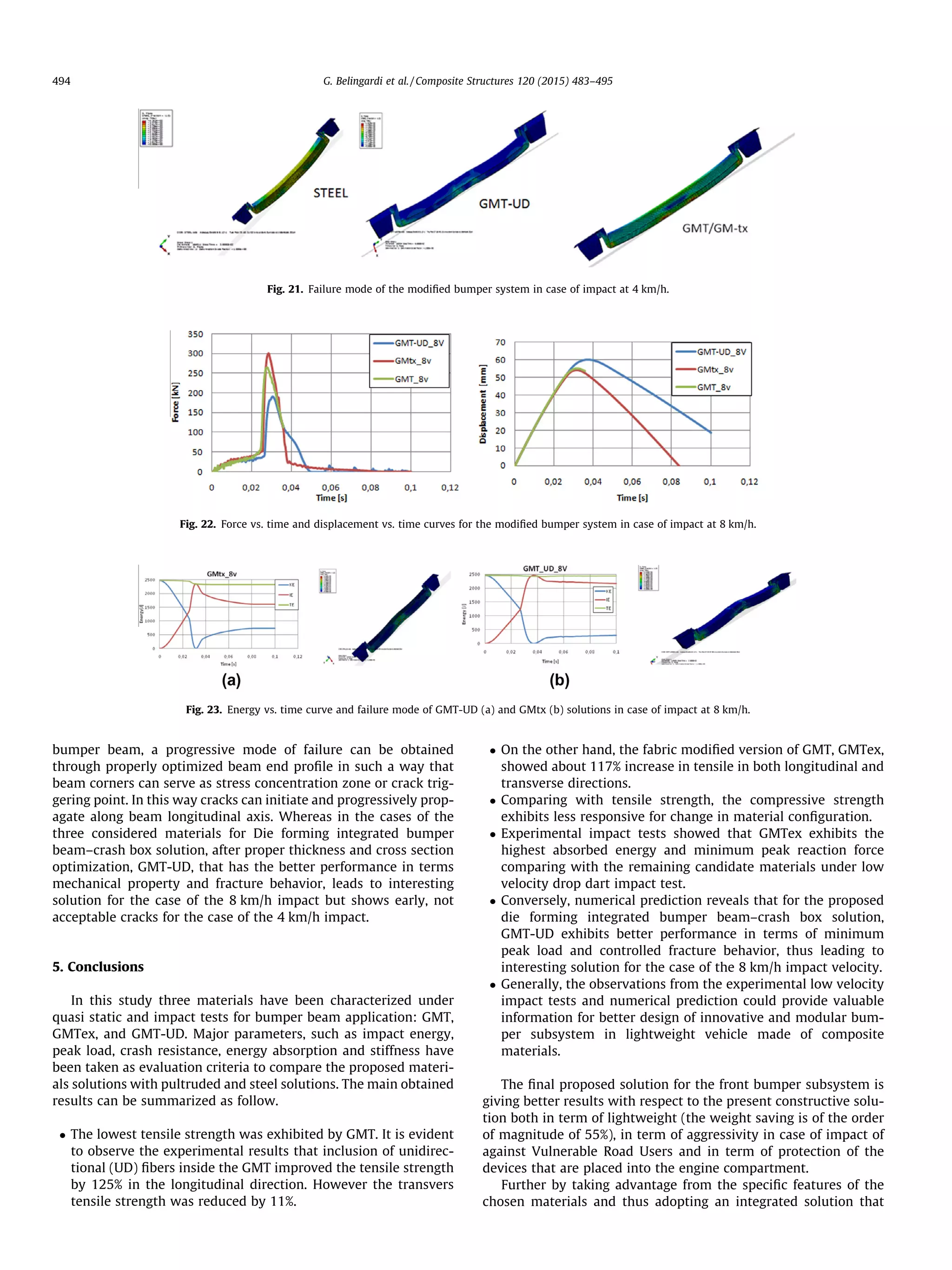
and energy time–history curves in Figs. 18 and 20. Failure mode
are shown in Fig. 21. For 4 km/h impact velocity, which is close
to parking load, the bumper has to operate within elastic range,
therefore besides bumping and, eventually, a minor cosmetic dam-
age, a complete fracture, as we observed on GMT-UD solution, is
not acceptable. Therefore, with the proposed beam configuration
and for the considered loading conditions (i.e. at low velocity
impact) the wall thickness obtained from Eq. (6) i.e. using equal
stiffness approach, leads to acceptable results only for GMT and
GMtx and can be considered for material replacement with signif-
icant weight saving but for GMT-UD the beam is fractured and
therefore the wall thickness asks for further changes.
The above proposed solutions have been also cheeked at higher
impact velocity, i.e. at 8 km/h. From force vs. time curve of Fig. 22,
it can be observed that there are two modes of deformation at this
higher velocity, after the initial phase of elastic deformation up to
25–40 kN, which is a behavior similar that observed at lower
velocity impact (at 4 km/h), a complete fracture of GMT and GMtx
beams at their central part comes out. Finally the other portions of
the fractured beam impact against the rigid wall but without fur-
ther material fracture. This phenomenon yields relatively higher
peak loads i.e. 265 kN, and 300 kN for GMT and GMtx solutions
Fig. 15. Reaction force vs. displacement and energy vs. displacement for the three materials considered [8].
Fig. 16. Force vs. time and force vs. displacement curves for the design solutions in steel and in equal thickness of the three considered materials.
Table 4
Thickness and mass of the combined beam–crash-box.
Material Steel GMT GMtx GMT-UD
Thickness [mm] 2.2 7.1 6.1 5.8
Mass [kg] 7.67 3.72 3.32 3.2
492 G. Belingardi et al. / Composite Structures 120 (2015) 483–495](https://image.slidesharecdn.com/j-210913145700/75/J-compstruct-2014-10-007-10-2048.jpg)
![respectively. Whereas, GMT-UD solution shows symptom of
further fractures during the second phase of the impact which
are definitely due to fractures along the width of the plate. This
results in relatively smaller peak load i.e. 170 kN. The failure
behaviors of the two solutions based on GMT-UD and GMTex can
be observed in Fig. 23.
In general, the modification made on classical GMT is indeed
improving both the tensile and impact performance of the original
material and can be used for structural purposes in some
application in place of steel and aluminum. However, coming to
energy absorbing components, having the composite materials a
completely different failure behavior than the conventional metal-
lic materials, the energy absorbing performance is strongly
affected by the geometry of the component. The direct adoption
of the traditional metallic energy absorbing geometry may lead
to a catastrophic failure and yield higher peak loads. As it has been
pointed out in the previous study [8] in the case of transversally
loaded energy absorbing composite components, like automotive
Fig. 17. Force vs. time and displacement vs. time curve for the modified bumper system.
Fig. 18. Energy vs. displacement and force vs. displacement curves for the modified bumper system in case of impact at 4 km/h.
Fig. 19. Energy curve for (a) steel and (b) GMT-UD solutions in case of impact at 4 km/h.
Fig. 20. Energy curve for (a) GMtx and (b) GMT solutions in case of impact at 4 km/h.
G. Belingardi et al. / Composite Structures 120 (2015) 483–495 493](https://image.slidesharecdn.com/j-210913145700/75/J-compstruct-2014-10-007-11-2048.jpg)
![includes into one single part both the bumper transverse beam and
the two crash-boxes, a great simplification of the manufacturing
process is achieved.
References
[1] Campbell FC. Manufacturing processes for advanced composites. Elsevier;
2004.
[2] Cheon SS, Choi JH, Lee DG. Development of the composite bumper beam for
passenger cars. Compos Struct 1995;32:491–9.
[3] Kim KJ, Won ST. Effect of structural variables on automotive body bumper
impact beams. Int J Automot Technol 2008;6:713–7.
[4] Jimenez A, Miravete A, Larrode E, Revuelta D. Effect of trigger geometry on
energy absorption in composite profiles. Compos Struct 2004;48:107–11.
[5] Davoodi MM, Sapuan SM, Ahmad Aidy D, Khalina A, Jonoobi M. Concept
selection of car bumper beam with developed hybrid bio-composite material.
Mater Des 2011:4857–65.
[6] Tabiei A, Svenson A, Hargarvec M, Bankd L. Impact performance of pultruded
beams for highway safety applications. Compos Struct 1998;42:231–7.
[7] Boria S, Belingardi G. Numerical investigation of energy absorbers in composite
materials for automotive applications. Int J Crashworthiness 2012:345–56.
[8] Belingardi G, Beyene AT, Koricho EG. Geometrical optimization of bumper
beam profile made of pultruded composite by numerical simulation. Compos
Struct 2013;102:217–25. http://dx.doi.org/10.1016/j.compstruct.2013.02.013.
[9] Belingardi G, Koricho EG, Martorana B. Implementation of composite and
recyclable thermoplastic materials for automotive bumper subsystem. Int J
Automot Compos 2013.
[10] Bank LC, Gentry TR. Development of a pultruded composite material highway
guardrail. Composite: Part A 2001;32:1329–38.
[11] Palmer DW, Bank LC, Gentry TR. Progressive tearing failure of pultruded
composite box beams: experiment and simulation. Compos Sci Technol
1998;58(8):1353–9.
[12] Belingardi G, Vadori R. Low velocity impact tests of laminate glass–fiber–
epoxy matrix composite material plates. Int J Impact Eng 2002;27:213–29.
G. Belingardi et al. / Composite Structures 120 (2015) 483–495 495](https://image.slidesharecdn.com/j-210913145700/75/J-compstruct-2014-10-007-13-2048.jpg)


![[IJET V2I5P22] Authors: Gangasani Ravikumar Reddy, M.Suneetha](https://cdn.slidesharecdn.com/ss_thumbnails/ijet-v2i5p22-161107145137-thumbnail.jpg?width=640&height=640&fit=bounds)


