Downloaded 17 times
![IJSRD - International Journal for Scientific Research & Development| Vol. 3, Issue 10, 2015 | ISSN (online): 2321-0613
All rights reserved by www.ijsrd.com 720
Design and Analysis of Nose Landing Gear Supportive Bracket by
Varying Stress Concentration Area, Based on ANSYS
Raviteja B1
Srinivas Prasad S2
P.S Subrahmanyam3
N.V.S.Anil Babu Javaji4
Chethana.K.Y5
1,2,3,4
Department Of Mechanical Engineering
1,2,3
NOVA College of Engineering and Technology, Department of mechanical Engineering,Jupudi(V),
Ibrahimpatnam(M), Krishna(DT), Andhra Pradesh – India
4
AMC Engineering College, Department of mechanical Engineering, Bangalore -560072, India
Abstract— Nose landing gear support bracket is one of the
main parts in the nose landing gear assembly, whose
function is to maintain the stability of the landing gear
during the movements. This work is focused on the FEA
analysis of support bracket by varying the stress
concentration area, The objective of this work is to
determine the static and modal analysis of support bracket
with different stress concentration areas, then analysis is
done using ANSYS WORKBENCH, These results could
provide some useful suggestions for design and
improvement for the better component
.Key words: Nose landing gear support bracket, Stress
concentration area, FEA, Static analysis, Modal analysis,
ANSYS WORKBENCH.
I. INTRODUCTION
Engineering machines and structure in service, experiences
stress, strain vibration, and their design generally requires
consideration of their dynamic behavior. The type of input
forces experienced by different components of aerospace in
service is dynamic. The progressive, localized and
permanent structure change that occurs in a material
subjected to stress concentration area and fluctuating strains
at nominal stresses that have maximum values less than the
tensile strength of the material which may culminates in
cracks and causes fracture after a sufficient number of
fluctuations.
Durability design of any component of an
aerospace structure plays an important role to ensure
reliability. The total damage and life of a structure is due to
a combination of static and dynamic loads arising from
engine vibrations, service load. The basic aim is to enable
stress strain and deformation calculations to be done at the
design stage of a development process. It is necessary to
clarify the modal analysis to obtain the natural frequency of
the component or structure.
Ravi Kumar [1] investigates the fatigue analysis of nose
landing gear support bracket with 4mm rectangular slot by
taking into the x direction loading and z direction loading to.
In their work they attempt to establish a comprehensive
mathematical model for obtaining the static analysis and
fatigue results.
Prasad kabade and Ravi ligannanavar [2] investigates design
and analysis of landing gear lug attachment in an airframe
by considering the standard passenger planes of 150-200
seating capacity the approximate specification and obtained
the failure of the lug,failure of the pin by considering the
axial and Transeverse loads,FEA is used to carryout and
compare the design calculations and determine the stress
concentration factor in order to estimate the maximum local
tensile stress.
Norman s.Currey[3] shows the aircraft landing gear
design.
Anil kumar.Matta[4] investigates the design optimization of
landing gear’s leg for unmanned aerial vehicle he obtained
the optimized leg’s weight and thickness results by
kinematic analysis
II. COMPONENTS USED FOR TEST
For the present study, Four models are used for
analysis.SAE1045 Steel is the material, Model with
rectangular 4mm slot as the present working
component[1],by changing the slots like circular, single
Double V slots another three models are designed.
III. FINITE ELEMENT ANALYSIS OF COMPONENT
The component is modeled using CATIA V5 software.
Manufacture of the component and geometric dimensions
there on are used to model the component. Using the cross
sectional area, the part is extruded. Displacement boundary
conditions on the model with all degree of freedom
constrained on the surfaces.
Also the evaluated engineering properties of the
component are given in Table 1
Property Unit
Density Kg/m3
7870
Modulus of Elasticity
GPa
202
Poisson’s ratio 0.3
Yield strength MPa 380
Ultimate strength MPa 724
Table 1: Engineering Properties of SAE 1045 Steel
component
IV. FINITE ELEMENT ANALYSIS OF COMPONENT
The component is modeled using solid edge
software. Manufacture of the component and geometric
dimensions there on are used to model the component.
Using the cross sectional area, the part is extruded.
Displacement boundary conditions on the model with all
degree of freedom constrained on the surfaces
Fig. 1: Meshed model with rectangular slot component](https://image.slidesharecdn.com/ijsrdv3i100327-160125105338/75/Design-and-Analysis-Nose-Landing-Gear-Support-1-2048.jpg)
![Design and Analysis of Nose Landing Gear Supportive Bracket by Varying Stress Concentration Area, Based on ANSYS
(IJSRD/Vol. 3/Issue 10/2015/154)
All rights reserved by www.ijsrd.com 722
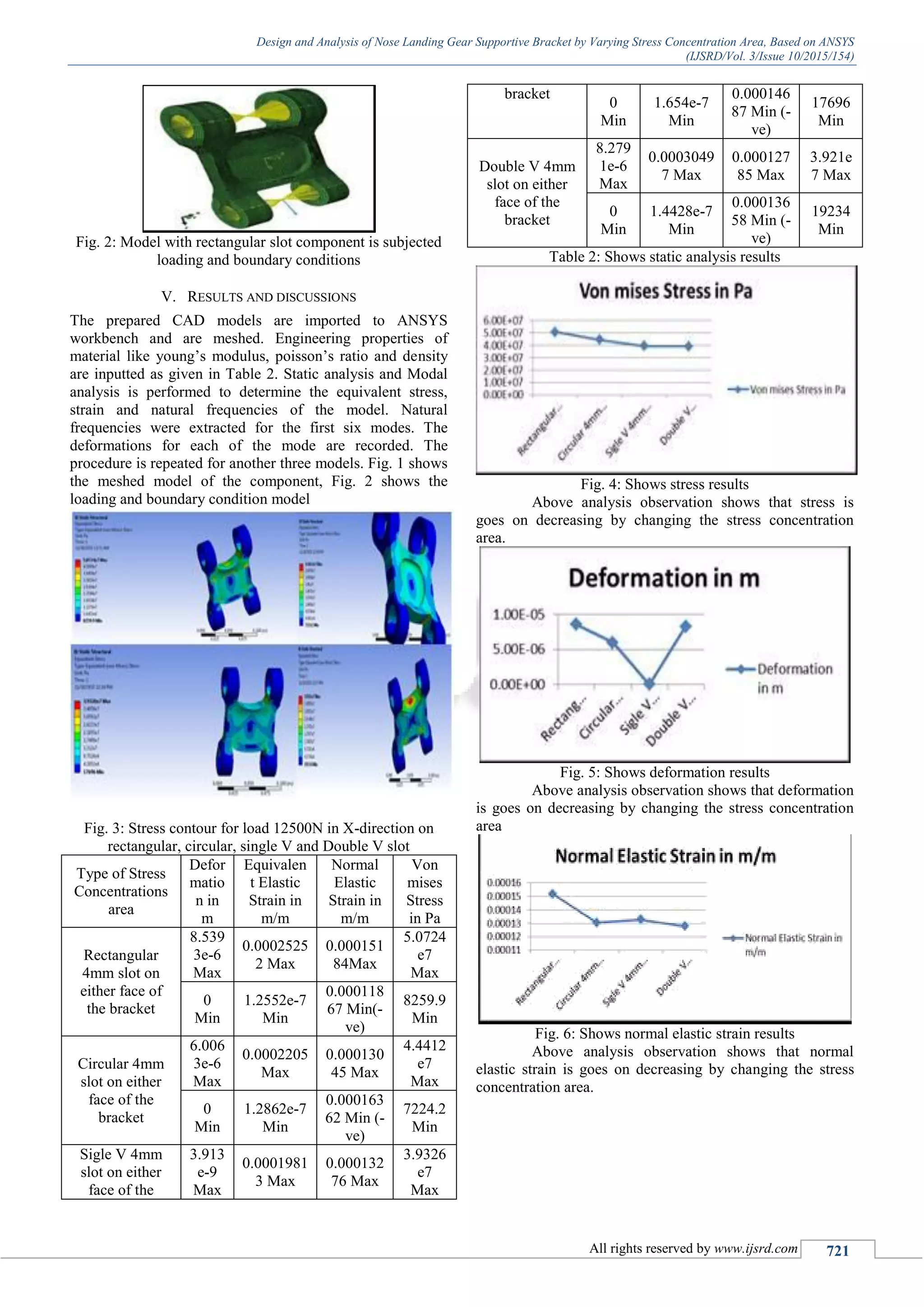
Fig. 7: Shows modal analysis results of rectangular, circular,
single V, double V components
Type of Stress
Concentration area
M
OD
E 1
M
OD
E 2
M
OD
E 3
M
OD
E 4
M
OD
E 5
M
OD
E 6
Rectangular 4mm
slot on either face of
the bracket
832
1
130
38
137
28
143
57
165
91
181
53
Circular 4mm slot on
either face of the
bracket
865
2.6
135
24
135
81
138
35
166
26
193
26
single V 4mm slot
on either face of the
bracket
843
8.7
132
07
137
24
140
49
174
89
179
89
Double V 4mm slot
on either face of the
bracket
840
9.6
130
72
138
62
147
91
175
17
187
72
Table 3: Shows Modal analysis results
Fig. 8: Shows Modal analysis results
Above observation shows that by changing the
stress concentration area natural frequency of the models
will not much varies in these components
VI. CONCLUSIONS
Deformation goes on decreases by changing the stress
concentration area in the order of circular, single v slot,
double v slot. Stress and strains also decreases by changing
the stress concentration area in the order of circular, single v
slot, double v slot.
Changing of the stress concentration area is not
much effect on the natural frequency of the component
obtained frequencies are of same order
REFERENCES
[1] Marcelino P, Nascimento, Herman J.C, Voorwald, Joao
da C, Payao Filho, “Fatigue strength of tungsten
inert gas repaired weld joints in airplane critical
structures”, Journal of Material processing
Technology, Vol.211, 2011, pp 1126-1135.
[2] Ossa E.A, “Failure Analysis of civil aircraft landing
gear”, Engineering Failure Analysis, Vol.13, 2006, pp
1177-83.
[3] Joy Xiaoya Tao, Steve Smith, Andrew Duff “The effect
of overloading sequences on landing gear fatigue
damage”, International Journal of Fatigue, Vol.31, 2009
pp 1837-1847.
[4] De Farias Azevedo CR, Hippert E, “Fracture of an
aircrafts landing gear”, Engineering Failure Analysis,
Vol.9, 2002, pp 265-75.](https://image.slidesharecdn.com/ijsrdv3i100327-160125105338/75/Design-and-Analysis-Nose-Landing-Gear-Support-3-2048.jpg)

This document presents a design and finite element analysis of a nose landing gear supportive bracket, focusing on varying stress concentration areas. The analysis, conducted using ANSYS, aims to understand the effects on static and modal performance, revealing that changes in stress concentration areas decrease deformation, stress, and strain without significantly affecting natural frequencies. Various models with different slot designs were tested, demonstrating a systematic reduction in these parameters with circular slots yielding the best results.