Booming demand for electricity, especially in the developing countries, has raised power generation technologies in the headlines. At the same time the discussion about causes of global warming has focused on emissions originating from power generation and on CO2 reduction technologies such as:
(1) Alternative primary energy sources,
(2) Capture and storage of CO2,
(3) Increasing the efficiency of converting primary energy content into electricity.
In the dissertation, the thermal efficiency of the power plant is improved when Control of furnace draft (nearer to balanced draft). Oxygen level decreases percentage of flue gases. Above this level heat losses are increases & below this carbon mono-oxide is formed. Steam power plant is using fuel to generate electrical power. The used of the fuel must be efficient so the boiler can generate for the maximum electrical power. By the time the steam cycle in the boiler, it also had heat losses through some parts and it effect on the efficiency of the boiler. This project will analyze about the parts of losses and boiler efficiency. to find excess air which effect heat losses in boiler. By using the 27 MW coal fired thermal power plant of Birla Corporation Limited, Satna (M.P.) the data is collect by using types of Combustion & heat flow in boiler. Result of the analysis show that the efficiency of boiler depends on mass of coal burnt & type of combustion .This study is fulfilling the objective of analysis to find the boiler efficiency and heat losses in boiler for 27 MW thermal power plant of Birla Corporation Limited, Satna (M.P.)
HPGCL Thermal power plant Summer Training reportRakesh Gothwal
Thermal power plant summer training report at Rajiv Gandhi Thermal Power plant at khedar Hisar (Haryana) which provides 2×600 Mw power . Haryana state would be able to provide additional 288 lac units per day to its consumers.
the water that reaches the surface is not hot enough to produce steam, it can still be used to produce electricity by feeding it into a Binary Power Plant. The hot water is fed into a heat exchanger. The heat from the water is absorbed by a liquid such as isopentane which boils at a lower temperature. The isopentane steam is used to drive turbines, producing electricity. The isopentane then condenses back to its liquid state and is used again.
The Thermal Power Station burns fuel & uses the resultant to make the steam, which derives the turbo generator. The Fuel i.e. coal is burnt in pulverized from. The pressure energy of the steam produce is converted into mechanical energy with the help of turbine. The mechanical energy is fed to the generator where the magnet rotate inside a set of stator winding & thus electricity is produced in India 65% of total power is generated by thermal power stations. To understand the working of the Thermal Power Station plant, we can divide the whole process into following parts.
Detailed Internship Report about RAJIV GANDHI COMBINED CYCLE POWER PLANT-NTPC LTD. Includes information about Thermodynamic Cycles, Combined Cycle, HRSG (Heat Recovery Steam Generator), and various components of a Combined Cycle Power Plant.
Water Efficiency in Thermal power PlantAtanu Maity
Ministry of Environment, Forest and Climate Change (MoEF)
in its recent notification dated December 07, 2015 on
Environment (Protection) Amendment Rules, 2015 have
notified the following:
I. All plants with Once Through Cooling (OTC) shall install Cooling Tower (CT) and achieve specific water consumption upto maximum of 3.5m3/MWh within a period of two years from the date of publication of this notification.
II. All existing CT-based plants shall have to reduce specific water consumption upto maximum of 3.5m3/MWh within a period of two years from the date of publication of this notification.
III. New plants to be installed after 1st January, 2017 shall have to meet specific water consumption upto maximum of 2.5 m3/MWh and achieve zero waste water discharged.
In light of the above a presentation on water consumption in cooling towers / Air Cooled Condensers and other comparisons.
Now a day’s power generation is most important for
every country. This power is generated by some thermal
cycles. But single cycle cannot be attain complete power
requirements and its efficiency also very low so that to fulfill
this requirements to combine two or more cycles in a single
power plant then we can increase the efficiency of the power
plant. Its increased efficiency is more than that of if the plant
operated on single cycle. In which we are using two different
cycles and these two cycles are operated by means of different
working mediums. These type of power plants we can called
them like combined cycle power plants. In combined cycle
power plants above cycle is known as topping cycle and below
cycle is known as bottoming cycle. The above cycle generally
brayton cycle which uses air as a working medium. When the
power generation was completed the exhaust gas will passes
in to the waste heat recovery boiler. Another cycle also
involved in bottoming cycle. This cycle works on the basis on
rankine cycle. In which steam is used as working medium.
The main component in bottoming cycle is waste heat
recovery boiler. It will receive exhaust heat from the gas
turbine and converts water in to steam. The steam used for
generating power by expansion on steam turbine. Combined
cycle power plants are mostly used in commercial power
plants.
In this paper we are analyzing one practical
combined cycle power plant. In practical conditions due to
some losses it can not be generates complete power. So that
we are invistigated why it is not give that much of power and
the effect of various operating parameters such as maximum
temperature and pressure of rankine cycle, gas turbine inlet
temperature and pressure ratio of Brayton cycle on the net
output work and thermal efficiency of the combine cycle
power plant.
The outcome of this work can be utilized in order to
facilitate the design of a combined cycle with higher efficiency
and output work. Mathematical calculations and simple
graphs in ms excel, and auto cad has been carried out to
study the effects and influences of the above mentioned
parameters on the efficiency and work output.
Thermal Power Plant Boiler Efficiency ImprovementAnkur Gaikwad
Boiler is one of the central equipment used in power generation & chemical process industries. Consequently, improving boiler efficiency is instrumental in bringing down costs substantially with a few simple measures. Some of these measures are discussed in this presentation
introduction to thermal powerplant,type of thermal powerplant,captive powerplant,rankin cycle,co-generation powerplant,subcritical powerplant,supercritical powerplant,theory of operation,working principle,parts of powerplant,boiler,turbine,etc
This paper of finite element analysis of the rib cage model is applied to recognize stress distributions and to determine the rate of bone fractures(especially for pathologically changed bones). Also to determine the load and stress to occurs on the human rib cage at any accident. Also find the maximum load sustain capacity of human rib cage and according to the load sustain capacity of the human rib cage by finite element analysis and search a material as like a bone cement and it take on a rib fracture and see the result . This paper is only of to nullify the rib fracture as present medical treatment give the elastic belt but due to respiration, the human ribs are contract and relax that’s the rib fracture are only minimize not a nullify. The human models are considered in between age 15 to 40 year. The Simulation result shows a good agreement with the cadaver test data.
Vibration control of newly designed Tool and Tool-Holder for internal treadi...IJMER
Machining processes are manufacturing methods for ensuring processing quality, usually within
relatively short periods and at low cost. Several machining parameters, such as cutting speed, feed rate, work
piece material, and cutting tool geometry have significant effects on the process quality. Many researchers have
studied the impact of these factors. The cutting tool overhang affects the surface quality, especially during the
internal turning process, but this has not been reviewed much [9].
The Effect of insertion of different geometries on heat transfer performance ...IJMER
Under turbulent flow conditions, the increase in heat transfer rate is more significant than
that under laminar flow conditions. The turbulent effects become a dominant factor over secondary flow
at higher Reynolds number. The turbulent flow can be produced by inserting different geometries in the
circular pipe. This study focuses on the various methods or geometries used to produce turbulent
geometries and its effect on the heat transfer. The turbulent generators with different geometrical
configurations have been used as one of the passive heat transfer enhancement techniques and are the
most widely used in tubes in several heat transfer applications. Insertion of such geometries may lead to
increase the friction factor and pressure drop which directly enhances the heat transfer characteristics.
MK-Prototypes: A Novel Algorithm for Clustering Mixed Type Data IJMER
Clustering mixed type data is one of the major research topics in the area of data mining. In
this paper, a new algorithm for clustering mixed type data is proposed where the concept of distribution
centroid is used to represent the prototype of categorical variables in a cluster which is then combined
with the mean to represent the prototype of clusters with mixed type variables. In the method, data is
observed from different views and the variables are grouped into different views. Those instances that
can be viewed differently from different viewpoints can be defined as multiview data. During clustering
process the differences among views are ignored in usual cases. Here, both views and variables weights
are computed simultaneously. The view weight is used to determine the closeness or density of view and
variable weight is used to identify the significance of each variable. With the intention of determining
the cluster of objects both these weights are used in the distance function. In the proposed method,
enhancement to the k-prototypes is done so that it automatically computes both view and variable
weights. The proposed algorithm MK-Prototypes algorithm is compared with two other clustering
algorithms.
Evaluation of Tensile and Flexural Properties of Polymer Matrix CompositesIJMER
International Journal of Modern Engineering Research (IJMER) is Peer reviewed, online Journal. It serves as an international archival forum of scholarly research related to engineering and science education.
Tracking of Maximum Power from Wind Using Fuzzy Logic Controller Based On PMSGIJMER
Wind energy has gained a growing worldwide interest due to the nonstop rise in fuel cost. The main aim of the wind-energy system is to extract the maximum power present in the wind stream. In order to extract the highest power, the maximum power point tracking (MPPT) algorithm is used. This paper proposes the fuzzy logic MPPT controller to track the maximum power from the wind generation
system. The maximum power is achieved based on the rotor speed of the wind system which consists of
wind turbine and PMSG. The error and change in error is given as input to the fuzzy logic and its output
is connected to the boost converter. The voltage from the dc link is controlled by the Voltage Source
Inverter (VSI), and it is placed in grid side converter control. The proposed system is designed and evaluated in MATLAB/SIMULINK. Simulation results show the good dynamic performance of the proposed system.
This presentation was given to the master class Environment and Development (ENP 33306) under the Social Sciences Group at the Wageningen University (April 22,2015). The core of the topic is upgrading in the value chain. The elements in the vertical and horizontal dimensions of the value chain and the capabilities literature are the theoretical lens used to gain a deeper understanding of upgrading. The theory has been applied to the cases of Philippine tuna fishery.
Scope of Improving Energy Utilization in Coal Based Co-Generation on Thermal ...IJMER
International Journal of Modern Engineering Research (IJMER) is Peer reviewed, online Journal. It serves as an international archival forum of scholarly research related to engineering and science education.
Energy Based Analysis of a Thermal Power Station for Energy Efficiency Improv...IJMER
Despite of growth of renewable energy stations installations like wind, solar, Tidal power, the energy for the world depends heavily on fossil fuels for electricity generation. It is also expected to continue the dependence on fossil fuels for next few decades. Therefore, given the continued reliance on the fossil fuels for some time, it is important to note these plants must reduce their environmental impact by operating fossil fuels more efficiently. Two types of analysis namely, energy and exergy analysis can be developed for the system. Energy analysis based on first law of thermodynamics cannot be applied as it cannot justify the real useful energy loss because it does not differentiate between the quality and quantity of energy within the system. Whereas, exergy analysis will characterize the work potential of a system based on the second law of thermodynamics and the maximum work that can be obtained from the system when its state is brought to the reference or dead state (standard atmospheric conditions).This technical paper presents the results of exergy and energy analysis carried out on 62 MW coal-based thermal power plant to evaluate the performance. The performance of the plant was estimated by a component-wise modeling followed by a system simulation. A parametric study is conducted for the thermal plant under various operating conditions, including different operating condenser pressures, temperatures and flow rates of cooling water across the condenser etc, in order to determine which parameter that maximizes plant performance. Energy loss distribution to find out the amount and source of irreversibilities generated in boiler and turbine in a plant so that any process in the system having largest energy destruction can be identified and that helps the designer to re design the system components.
GENERATION OF POWER THROUGH HYDROGEN – OXYGEN FUEL CELLSinventy
Research Inventy : International Journal of Engineering and Science is published by the group of young academic and industrial researchers with 12 Issues per year. It is an online as well as print version open access journal that provides rapid publication (monthly) of articles in all areas of the subject such as: civil, mechanical, chemical, electronic and computer engineering as well as production and information technology. The Journal welcomes the submission of manuscripts that meet the general criteria of significance and scientific excellence. Papers will be published by rapid process within 20 days after acceptance and peer review process takes only 7 days. All articles published in Research Inventy will be peer-reviewed.
Investigating The Performance of A Steam Power PlantIJMERJOURNAL
ABSTRACT: The performance analysis of Shobra El-Khima power plant in Cairo, Egypt is presented based on energy and exergy analysis to determine the causes , the sites with high exergy destruction , losses and the possibilities of improving the plant performance. The performance of the plant was evaluated at different loads (Full, 75% and, 50 %). The calculated thermal efficiency based on the heat added to the steam was found to be 41.9 %, 41.7 %, 43.9% , while the exergetic efficiency of the power cycle was found to be 44.8%, 45.5% and 48.8% at max, 75% and, 50 % load respectively. The condenser was found to have the largest energy losses where (54.3%, 55.1% and 56.3% at max, 75% and, 50 % load respectively) of the added energy to the steam is lost to the environment. The maximum exergy destruction was found to be in the turbine where the percentage of the exergy destruction was found to be (42%, 59% and 46.1% at max, 75% and, 50 % load respectively). The pump was found to have the minimum exergy destruction. It was also found that the exergy destruction in feed water heaters and in the condenser together represents the maximum exergy destruction in the plant (about 52%). This means that the irreversibilities in the heat transfer devices in the plant have a significant role on the exergy destruction. So, it is thought that the improvement in the power plant will be limited due to the heat transfer devices.
Flexible operation and heat rate in thermal power plant.pptxAbhishekVerma847053
thermal power plant flexible operation and optimization in heat rate during flexible operation in thermal power plant from national power training institute, NPTI NAGPUR
its a short introduction of pollution due to power generation and thermal power impact and analyse of hydro power plant its equation use in producing electric energy by Seminar Report
pollution due to non conventional energy of power generation
A Study on Translucent Concrete Product and Its Properties by Using Optical F...IJMER
- Translucent concrete is a concrete based material with light-transferring properties,
obtained due to embedded light optical elements like Optical fibers used in concrete. Light is conducted
through the concrete from one end to the other. This results into a certain light pattern on the other
surface, depending on the fiber structure. Optical fibers transmit light so effectively that there is
virtually no loss of light conducted through the fibers. This paper deals with the modeling of such
translucent or transparent concrete blocks and panel and their usage and also the advantages it brings
in the field. The main purpose is to use sunlight as a light source to reduce the power consumption of
illumination and to use the optical fiber to sense the stress of structures and also use this concrete as an
architectural purpose of the building
Developing Cost Effective Automation for Cotton Seed DelintingIJMER
A low cost automation system for removal of lint from cottonseed is to be designed and
developed. The setup consists of stainless steel drum with stirrer in which cottonseeds having lint is mixed
with concentrated sulphuric acid. So lint will get burn. This lint free cottonseed treated with lime water to
neutralize acidic nature. After water washing this cottonseeds are used for agriculter purpose
Study & Testing Of Bio-Composite Material Based On Munja FibreIJMER
The incorporation of natural fibres such as munja fiber composites has gained
increasing applications both in many areas of Engineering and Technology. The aim of this study is to
evaluate mechanical properties such as flexural and tensile properties of reinforced epoxy composites.
This is mainly due to their applicable benefits as they are light weight and offer low cost compared to
synthetic fibre composites. Munja fibres recently have been a substitute material in many weight-critical
applications in areas such as aerospace, automotive and other high demanding industrial sectors. In
this study, natural munja fibre composites and munja/fibreglass hybrid composites were fabricated by a
combination of hand lay-up and cold-press methods. A new variety in munja fibre is the present work
the main aim of the work is to extract the neat fibre and is characterized for its flexural characteristics.
The composites are fabricated by reinforcing untreated and treated fibre and are tested for their
mechanical, properties strictly as per ASTM procedures.
Hybrid Engine (Stirling Engine + IC Engine + Electric Motor)IJMER
Hybrid engine is a combination of Stirling engine, IC engine and Electric motor. All these 3 are
connected together to a single shaft. The power source of the Stirling engine will be a Solar Panel. The aim of
this is to run the automobile using a Hybrid engine
Fabrication & Characterization of Bio Composite Materials Based On Sunnhemp F...IJMER
The present day technology demands eco-friendly developments. In this era the
composite material are playing a vital roal in different field of Engineering .The composite materials
are using as a principle materials. Nowaday the composite materials are utilizing as a important
component of engineering field .Where as the importance of the applications of composites is well
known, but thrust on the use of natural fibres in it for reinforcement has been given priority for some
times. But changing from synthetic fibres to natural fibres provides only half green-composites. A
partial green composite will be achieved if the matrix component is also eco-friendly. Keeping this in
view, a detailed literature surveyed has been carried out through various issues of the Journals
related to this field. The material systems used are sunnhemp fibres. Some epoxy and hardener has
been also added for stability and drying of the bio-composites. Various graphs and bar-charts are
super-imposed on each other for comparison among themselves and Graphs is plotted on MAT LAB
and ORIGIN 6.0 software. To determining tensile strengths, Various properties for different biocomposites
have been compared among themselves. Comparison of the behaviour of bio-composites of
this work has been also compare with other works. The bio-composites developed in this work are
likely to get applications in fall ceilings, partitions, bio-degradable packagings, automotive interiors,
sports things (e.g. rackets, nets, etc.), toys etc.
Geochemistry and Genesis of Kammatturu Iron Ores of Devagiri Formation, Sandu...IJMER
The Greenstone belts of Karnataka are enriched in BIFs in Dharwar craton, where Iron
formations are confined to the basin shelf, clearly separated from the deeper-water iron formation that
accumulated at the basin margin and flanking the marine basin. Geochemical data procured in terms of
major, trace and REE are plotted in various diagrams to interpret the genesis of BIFs. Al2O3, Fe2O3 (T),
TiO2, CaO, and SiO2 abundances and ratios show a wide variation. Ni, Co, Zr, Sc, V, Rb, Sr, U, Th,
ΣREE, La, Ce and Eu anomalies and their binary relationships indicate that wherever the terrigenous
component has increased, the concentration of elements of felsic such as Zr and Hf has gone up. Elevated
concentrations of Ni, Co and Sc are contributed by chlorite and other components characteristic of basic
volcanic debris. The data suggest that these formations were generated by chemical and clastic
sedimentary processes on a shallow shelf. During transgression, chemical precipitation took place at the
sediment-water interface, whereas at the time of regression. Iron ore formed with sedimentary structures
and textures in Kammatturu area, in a setting where the water column was oxygenated.
Experimental Investigation on Characteristic Study of the Carbon Steel C45 in...IJMER
In this paper, the mechanical characteristics of C45 medium carbon steel are investigated
under various working conditions. The main characteristic to be studied on this paper is impact toughness
of the material with different configurations and the experiment were carried out on charpy impact testing
equipment. This study reveals the ability of the material to absorb energy up to failure for various
specimen configurations under different heat treated conditions and the corresponding results were
compared with the analysis outcome
Non linear analysis of Robot Gun Support Structure using Equivalent Dynamic A...IJMER
Robot guns are being increasingly employed in automotive manufacturing to replace
risky jobs and also to increase productivity. Using a single robot for a single operation proves to be
expensive. Hence for cost optimization, multiple guns are mounted on a single robot and multiple
operations are performed. Robot Gun structure is an efficient way in which multiple welds can be done
simultaneously. However mounting several weld guns on a single structure induces a variety of
dynamic loads, especially during movement of the robot arm as it maneuvers to reach the weld
locations. The primary idea employed in this paper, is to model those dynamic loads as equivalent G
force loads in FEA. This approach will be on the conservative side, and will be saving time and
subsequently cost efficient. The approach of the paper is towards creating a standard operating
procedure when it comes to analysis of such structures, with emphasis on deploying various technical
aspects of FEA such as Non Linear Geometry, Multipoint Constraint Contact Algorithm, Multizone
meshing .
Static Analysis of Go-Kart Chassis by Analytical and Solid Works SimulationIJMER
This paper aims to do modelling, simulation and performing the static analysis of a go
kart chassis consisting of Circular beams. Modelling, simulations and analysis are performed using 3-D
modelling software i.e. Solid Works and ANSYS according to the rulebook provided by Indian Society of
New Era Engineers (ISNEE) for National Go Kart Championship (NGKC-14).The maximum deflection is
determined by performing static analysis. Computed results are then compared to analytical calculation,
where it is found that the location of maximum deflection agrees well with theoretical approximation but
varies on magnitude aspect.
In récent year various vehicle introduced in market but due to limitation in
carbon émission and BS Séries limitd speed availability vehicle in the market and causing of
environnent pollution over few year There is need to decrease dependancy on fuel vehicle.
bicycle is to be modified for optional in the future To implement new technique using change in
pedal assembly and variable speed gearbox such as planetary gear optimise speed of vehicle
with variable speed ratio.To increase the efficiency of bicycle for confortable drive and to
reduce torque appli éd on bicycle. we introduced epicyclic gear box in which transmission done
throgh Chain Drive (i.e. Sprocket )to rear wheel with help of Epicyclical gear Box to give
number of différent Speed during driving.To reduce torque requirent in the cycle with change in
the pedal mechanism
Integration of Struts & Spring & Hibernate for Enterprise ApplicationsIJMER
The proposal of this paper is to present Spring Framework which is widely used in
developing enterprise applications. Considering the current state where applications are developed using
the EJB model, Spring Framework assert that ordinary java beans(POJO) can be utilize with minimal
modifications. This modular framework can be used to develop the application faster and can reduce
complexity. This paper will highlight the design overview of Spring Framework along with its features that
have made the framework useful. The integration of multiple frameworks for an E-commerce system has
also been addressed in this paper. This paper also proposes structure for a website based on integration of
Spring, Hibernate and Struts Framework.
Microcontroller Based Automatic Sprinkler Irrigation SystemIJMER
Microcontroller based Automatic Sprinkler System is a new concept of using
intelligence power of embedded technology in the sprinkler irrigation work. Designed system replaces
the conventional manual work involved in sprinkler irrigation to automatic process. Using this system a
farmer is protected against adverse inhuman weather conditions, tedious work of changing over of
sprinkler water pipe lines & risk of accident due to high pressure in the water pipe line. Overall
sprinkler irrigation work is transformed in to a comfortableautomatic work. This system provides
flexibility & accuracy in respect of time set for the operation of a sprinkler water pipe lines. In present
work the author has designed and developed an automatic sprinkler irrigation system which is
controlled and monitored by a microcontroller interfaced with solenoid valves.
On some locally closed sets and spaces in Ideal Topological SpacesIJMER
In this paper we introduce and characterize some new generalized locally closed sets
known as
δ
ˆ
s-locally closed sets and spaces are known as
δ
ˆ
s-normal space and
δ
ˆ
s-connected space and
discussed some of their properties
Intrusion Detection and Forensics based on decision tree and Association rule...IJMER
This paper present an approach based on the combination of, two techniques using
decision tree and Association rule mining for Probe attack detection. This approach proves to be
better than the traditional approach of generating rules for fuzzy expert system by clustering methods.
Association rule mining for selecting the best attributes together and decision tree for identifying the
best parameters together to create the rules for fuzzy expert system. After that rules for fuzzy expert
system are generated using association rule mining and decision trees. Decision trees is generated for
dataset and to find the basic parameters for creating the membership functions of fuzzy inference
system. Membership functions are generated for the probe attack. Based on these rules we have
created the fuzzy inference system that is used as an input to neuro-fuzzy system. Fuzzy inference
system is loaded to neuro-fuzzy toolbox as an input and the final ANFIS structure is generated for
outcome of neuro-fuzzy approach. The experiments and evaluations of the proposed method were
done with NSL-KDD intrusion detection dataset. As the experimental results, the proposed approach
based on the combination of, two techniques using decision tree and Association rule mining
efficiently detected probe attacks. Experimental results shows better results for detecting intrusions as
compared to others existing methods
Natural Language Ambiguity and its Effect on Machine LearningIJMER
"Natural language processing" here refers to the use and ability of systems to process
sentences in a natural language such as English, rather than in a specialized artificial computer
language such as C++. The systems of real interest here are digital computers of the type we think of as
personal computers and mainframes. Of course humans can process natural languages, but for us the
question is whether digital computers can or ever will process natural languages. We have tried to
explore in depth and break down the types of ambiguities persistent throughout the natural languages
and provide an answer to the question “How it affects the machine translation process and thereby
machine learning as whole?” .
Today in era of software industry there is no perfect software framework available for
analysis and software development. Currently there are enormous number of software development
process exists which can be implemented to stabilize the process of developing a software system. But no
perfect system is recognized till yet which can help software developers for opting of best software
development process. This paper present the framework of skillful system combined with Likert scale. With
the help of Likert scale we define a rule based model and delegate some mass score to every process and
develop one tool name as MuxSet which will help the software developers to select an appropriate
development process that may enhance the probability of system success.
Material Parameter and Effect of Thermal Load on Functionally Graded CylindersIJMER
The present study investigates the creep in a thick-walled composite cylinders made
up of aluminum/aluminum alloy matrix and reinforced with silicon carbide particles. The distribution
of SiCp is assumed to be either uniform or decreasing linearly from the inner to the outer radius of
the cylinder. The creep behavior of the cylinder has been described by threshold stress based creep
law with a stress exponent of 5. The composite cylinders are subjected to internal pressure which is
applied gradually and steady state condition of stress is assumed. The creep parameters required to
be used in creep law, are extracted by conducting regression analysis on the available experimental
results. The mathematical models have been developed to describe steady state creep in the composite
cylinder by using von-Mises criterion. Regression analysis is used to obtain the creep parameters
required in the study. The basic equilibrium equation of the cylinder and other constitutive equations
have been solved to obtain creep stresses in the cylinder. The effect of varying particle size, particle
content and temperature on the stresses in the composite cylinder has been analyzed. The study
revealed that the stress distributions in the cylinder do not vary significantly for various combinations
of particle size, particle content and operating temperature except for slight variation observed for
varying particle content. Functionally Graded Materials (FGMs) emerged and led to the development
of superior heat resistant materials.
Energy Audit is the systematic process for finding out the energy conservation
opportunities in industrial processes. The project carried out studies on various energy conservation
measures application in areas like lighting, motors, compressors, transformer, ventilation system etc.
In this investigation, studied the technical aspects of the various measures along with its cost benefit
analysis.
Investigation found that major areas of energy conservation are-
1. Energy efficient lighting schemes.
2. Use of electronic ballast instead of copper ballast.
3. Use of wind ventilators for ventilation.
4. Use of VFD for compressor.
5. Transparent roofing sheets to reduce energy consumption.
So Energy Audit is the only perfect & analyzed way of meeting the Industrial Energy Conservation.
An Implementation of I2C Slave Interface using Verilog HDLIJMER
The focus of this paper is on implementation of Inter Integrated Circuit (I2C) protocol
following slave module for no data loss. In this paper, the principle and the operation of I2C bus protocol
will be introduced. It follows the I2C specification to provide device addressing, read/write operation and
an acknowledgement. The programmable nature of device provide users with the flexibility of configuring
the I2C slave device to any legal slave address to avoid the slave address collision on an I2C bus with
multiple slave devices. This paper demonstrates how I2C Master controller transmits and receives data to
and from the Slave with proper synchronization.
The module is designed in Verilog and simulated in ModelSim. The design is also synthesized in Xilinx
XST 14.1. This module acts as a slave for the microprocessor which can be customized for no data loss.
Discrete Model of Two Predators competing for One PreyIJMER
This paper investigates the dynamical behavior of a discrete model of one prey two
predator systems. The equilibrium points and their stability are analyzed. Time series plots are obtained
for different sets of parameter values. Also bifurcation diagrams are plotted to show dynamical behavior
of the system in selected range of growth parameter
Immunizing Image Classifiers Against Localized Adversary Attacksgerogepatton
This paper addresses the vulnerability of deep learning models, particularly convolutional neural networks
(CNN)s, to adversarial attacks and presents a proactive training technique designed to counter them. We
introduce a novel volumization algorithm, which transforms 2D images into 3D volumetric representations.
When combined with 3D convolution and deep curriculum learning optimization (CLO), itsignificantly improves
the immunity of models against localized universal attacks by up to 40%. We evaluate our proposed approach
using contemporary CNN architectures and the modified Canadian Institute for Advanced Research (CIFAR-10
and CIFAR-100) and ImageNet Large Scale Visual Recognition Challenge (ILSVRC12) datasets, showcasing
accuracy improvements over previous techniques. The results indicate that the combination of the volumetric
input and curriculum learning holds significant promise for mitigating adversarial attacks without necessitating
adversary training.
Explore the innovative world of trenchless pipe repair with our comprehensive guide, "The Benefits and Techniques of Trenchless Pipe Repair." This document delves into the modern methods of repairing underground pipes without the need for extensive excavation, highlighting the numerous advantages and the latest techniques used in the industry.
Learn about the cost savings, reduced environmental impact, and minimal disruption associated with trenchless technology. Discover detailed explanations of popular techniques such as pipe bursting, cured-in-place pipe (CIPP) lining, and directional drilling. Understand how these methods can be applied to various types of infrastructure, from residential plumbing to large-scale municipal systems.
Ideal for homeowners, contractors, engineers, and anyone interested in modern plumbing solutions, this guide provides valuable insights into why trenchless pipe repair is becoming the preferred choice for pipe rehabilitation. Stay informed about the latest advancements and best practices in the field.
NO1 Uk best vashikaran specialist in delhi vashikaran baba near me online vas...Amil Baba Dawood bangali
Contact with Dawood Bhai Just call on +92322-6382012 and we'll help you. We'll solve all your problems within 12 to 24 hours and with 101% guarantee and with astrology systematic. If you want to take any personal or professional advice then also you can call us on +92322-6382012 , ONLINE LOVE PROBLEM & Other all types of Daily Life Problem's.Then CALL or WHATSAPP us on +92322-6382012 and Get all these problems solutions here by Amil Baba DAWOOD BANGALI
#vashikaranspecialist #astrologer #palmistry #amliyaat #taweez #manpasandshadi #horoscope #spiritual #lovelife #lovespell #marriagespell#aamilbabainpakistan #amilbabainkarachi #powerfullblackmagicspell #kalajadumantarspecialist #realamilbaba #AmilbabainPakistan #astrologerincanada #astrologerindubai #lovespellsmaster #kalajaduspecialist #lovespellsthatwork #aamilbabainlahore#blackmagicformarriage #aamilbaba #kalajadu #kalailam #taweez #wazifaexpert #jadumantar #vashikaranspecialist #astrologer #palmistry #amliyaat #taweez #manpasandshadi #horoscope #spiritual #lovelife #lovespell #marriagespell#aamilbabainpakistan #amilbabainkarachi #powerfullblackmagicspell #kalajadumantarspecialist #realamilbaba #AmilbabainPakistan #astrologerincanada #astrologerindubai #lovespellsmaster #kalajaduspecialist #lovespellsthatwork #aamilbabainlahore #blackmagicforlove #blackmagicformarriage #aamilbaba #kalajadu #kalailam #taweez #wazifaexpert #jadumantar #vashikaranspecialist #astrologer #palmistry #amliyaat #taweez #manpasandshadi #horoscope #spiritual #lovelife #lovespell #marriagespell#aamilbabainpakistan #amilbabainkarachi #powerfullblackmagicspell #kalajadumantarspecialist #realamilbaba #AmilbabainPakistan #astrologerincanada #astrologerindubai #lovespellsmaster #kalajaduspecialist #lovespellsthatwork #aamilbabainlahore #Amilbabainuk #amilbabainspain #amilbabaindubai #Amilbabainnorway #amilbabainkrachi #amilbabainlahore #amilbabaingujranwalan #amilbabainislamabad
About
Indigenized remote control interface card suitable for MAFI system CCR equipment. Compatible for IDM8000 CCR. Backplane mounted serial and TCP/Ethernet communication module for CCR remote access. IDM 8000 CCR remote control on serial and TCP protocol.
• Remote control: Parallel or serial interface.
• Compatible with MAFI CCR system.
• Compatible with IDM8000 CCR.
• Compatible with Backplane mount serial communication.
• Compatible with commercial and Defence aviation CCR system.
• Remote control system for accessing CCR and allied system over serial or TCP.
• Indigenized local Support/presence in India.
• Easy in configuration using DIP switches.
Technical Specifications
Indigenized remote control interface card suitable for MAFI system CCR equipment. Compatible for IDM8000 CCR. Backplane mounted serial and TCP/Ethernet communication module for CCR remote access. IDM 8000 CCR remote control on serial and TCP protocol.
Key Features
Indigenized remote control interface card suitable for MAFI system CCR equipment. Compatible for IDM8000 CCR. Backplane mounted serial and TCP/Ethernet communication module for CCR remote access. IDM 8000 CCR remote control on serial and TCP protocol.
• Remote control: Parallel or serial interface
• Compatible with MAFI CCR system
• Copatiable with IDM8000 CCR
• Compatible with Backplane mount serial communication.
• Compatible with commercial and Defence aviation CCR system.
• Remote control system for accessing CCR and allied system over serial or TCP.
• Indigenized local Support/presence in India.
Application
• Remote control: Parallel or serial interface.
• Compatible with MAFI CCR system.
• Compatible with IDM8000 CCR.
• Compatible with Backplane mount serial communication.
• Compatible with commercial and Defence aviation CCR system.
• Remote control system for accessing CCR and allied system over serial or TCP.
• Indigenized local Support/presence in India.
• Easy in configuration using DIP switches.
Forklift Classes Overview by Intella PartsIntella Parts
Discover the different forklift classes and their specific applications. Learn how to choose the right forklift for your needs to ensure safety, efficiency, and compliance in your operations.
For more technical information, visit our website https://intellaparts.com
Industrial Training at Shahjalal Fertilizer Company Limited (SFCL)MdTanvirMahtab2
This presentation is about the working procedure of Shahjalal Fertilizer Company Limited (SFCL). A Govt. owned Company of Bangladesh Chemical Industries Corporation under Ministry of Industries.
Courier management system project report.pdfKamal Acharya
It is now-a-days very important for the people to send or receive articles like imported furniture, electronic items, gifts, business goods and the like. People depend vastly on different transport systems which mostly use the manual way of receiving and delivering the articles. There is no way to track the articles till they are received and there is no way to let the customer know what happened in transit, once he booked some articles. In such a situation, we need a system which completely computerizes the cargo activities including time to time tracking of the articles sent. This need is fulfilled by Courier Management System software which is online software for the cargo management people that enables them to receive the goods from a source and send them to a required destination and track their status from time to time.
Final project report on grocery store management system..pdfKamal Acharya
In today’s fast-changing business environment, it’s extremely important to be able to respond to client needs in the most effective and timely manner. If your customers wish to see your business online and have instant access to your products or services.
Online Grocery Store is an e-commerce website, which retails various grocery products. This project allows viewing various products available enables registered users to purchase desired products instantly using Paytm, UPI payment processor (Instant Pay) and also can place order by using Cash on Delivery (Pay Later) option. This project provides an easy access to Administrators and Managers to view orders placed using Pay Later and Instant Pay options.
In order to develop an e-commerce website, a number of Technologies must be studied and understood. These include multi-tiered architecture, server and client-side scripting techniques, implementation technologies, programming language (such as PHP, HTML, CSS, JavaScript) and MySQL relational databases. This is a project with the objective to develop a basic website where a consumer is provided with a shopping cart website and also to know about the technologies used to develop such a website.
This document will discuss each of the underlying technologies to create and implement an e- commerce website.
Water scarcity is the lack of fresh water resources to meet the standard water demand. There are two type of water scarcity. One is physical. The other is economic water scarcity.
To Improve Thermal Efficiency of 27mw Coal Fired Power Plant
1. International
OPEN ACCESS Journal
Of Modern Engineering Research (IJMER)
| IJMER | ISSN: 2249–6645 | www.ijmer.com | Vol. 4 | Iss. 2 | Feb. 2014 |35|
“To Improve Thermal Efficiency of 27mw Coal Fired Power
Plant”
Amit Kumar Vishwakarma1
, Gopal Kumar Choudhary2
, Rajendra Prasad Sahu3
1,2,3
Assistant Professor, Department of Mechanical Engineering, Technocrats Institute of Technology, Bhopal,
M.P 462021
I. INTRODUCTION
Thermal power plants convert heat (via mechanical energy) into electrical energy. The most important
types are coal, gas and nuclear power stations. Thermal power plants are the backbone of our electricity system.
Their efficiency is typically between 30 and 50%. Based on this, it is often concluded that thermal power
stations are inadequate, waste energy, and need to be replaced by ’better’ facilities. To evaluate this conclusion,
one needs to look at the physical properties of heat energy, as well as at the fine-print in efficiency calculations,
defined by man.
Rapid growth of electrical energy demand, not only in developing countries, discussions on fossil fuel
reserves and the impact of thermal power generation on global warming, have increased the focus on alternative
primary energy sources and the efficiency improvement techniques for the conversion of the fossil fuels into
electricity. Development efforts are ongoing to reduce, capture and/or store CO2 emitted from burning fossil
fuels. The following is a quote from the McKinsey report of May 2007 ―Curbing the energy demand growth‖.
QUOTE Reducing current losses from electricity generation and distribution is another substantial
opportunity. Power generation used 155 QBTUs (Quad =1015) – representing a hefty 37% of global energy use
– to generate 57 QBTUs of deliverable electricity in 2003. In short, close to two-thirds of the energy put to the
process is lost before it reaches the final end user.
UNQUOTE In this essay, we will look at some of the auxiliary load in fossil-fueled power stations and
see what can be done to reduce this part of the losses. Thermal power stations use 3% to 10 % of their gross
generation capacity for auxiliary processes. A conventional coal-fired thermal power plant uses slightly more (5
– 10%) of the electricity it produces for the auxiliary load. For a combined-cycle power plant, the auxiliary
consumption can be less than 3.5 %. Auxiliary processes are required to keep the generator running; they are,
ABSTRACT: Booming demand for electricity, especially in the developing countries, has raised
power generation technologies in the headlines. At the same time the discussion about causes of global
warming has focused on emissions originating from power generation and on CO2 reduction
technologies such as:
(1) Alternative primary energy sources,
(2) Capture and storage of CO2,
(3) Increasing the efficiency of converting primary energy content into electricity.
In the dissertation, the thermal efficiency of the power plant is improved when Control of furnace draft
(nearer to balanced draft). Oxygen level decreases percentage of flue gases. Above this level heat
losses are increases & below this carbon mono-oxide is formed. Steam power plant is using fuel to
generate electrical power. The used of the fuel must be efficient so the boiler can generate for the
maximum electrical power. By the time the steam cycle in the boiler, it also had heat losses through
some parts and it effect on the efficiency of the boiler. This project will analyze about the parts of
losses and boiler efficiency. to find excess air which effect heat losses in boiler. By using the 27 MW
coal fired thermal power plant of Birla Corporation Limited, Satna (M.P.) the data is collect by using
types of Combustion & heat flow in boiler. Result of the analysis show that the efficiency of boiler
depends on mass of coal burnt & type of combustion .This study is fulfilling the objective of analysis to
find the boiler efficiency and heat losses in boiler for 27 MW thermal power plant of Birla Corporation
Limited, Satna (M.P.)
Keywords: Rankine Cycle, AFBC Boiler, Ash Handling System, Coal Fired Thermal Power Plant
2. “To Improve Thermal Efficiency of 27mw Coal Fired Power Plant”
| IJMER | ISSN: 2249–6645 | www.ijmer.com | Vol. 4 | Iss. 2 | Feb. 2014 |36|
for instance, conveying fuel coal to coal mills and maintaining the cooling water flowing through the condenser.
Most of the auxiliary power demand, up to 80%, is used by large electric motors that are typically connected to
the medium voltage switchboard, supplied through auxiliary transformers. The increasing demand for ―clean
coal‖ and CO2 emission capture and storage technologies will increase the auxiliary electricity consumption of
electric power generation. Power stations, especially base-load ones, are running at full load all the time. It is
easy to imagine that not much change or control is needed for the auxiliary processes in such cases. The fact is
however, that very few power stations run at their maximum capacity throughout the year; instead the capacity
is being adjusted all the time to match demand and various operation conditions and parameters. See Figure 1
illustrating a one year capacity utilization curve and Figure 2 for the corresponding operating hours of a 27 MW
steam generator
Fig 1: CAPACITY UTILIZATION CURVE OF A 27 MW STEAM GENERATOR.
Fig 2: OPERATING HOURS AT VARIOUS LOAD RANGES OF A 27 MW STEAM GENERATOR.
1.1 EFFICIENCY:
The efficiency of a power station is indicated with the Greek character n, and is defined
as follows:
η =
𝑜𝑢𝑡𝑝𝑢𝑡 𝑜𝑓 𝑠𝑡𝑎𝑡𝑖𝑜𝑛
𝑖𝑛𝑝𝑢𝑡 𝑜𝑓 𝑠𝑡𝑎𝑡𝑖𝑜𝑛
X100
This definition applies to any power plant. It seems to be straight forward, but in practice, a few
problems arise with it. First, power plants themselves use electricity for their operation (lighting, pumps, etc.).
Using the total amount of electricity generated yields the ’gross Efficiency’, while subtracting the power plants
own use gives ’net efficiency’. Comparisons are only meaningful based on net efficiency.
The energy efficiency of a conventional thermal power station, considered as salable energy as a
percent of the heating value of the fuel consumed, is typically 33% to 48%. This efficiency is limited as all heat
engines are governed by the laws of thermodynamics. The rest of the energy must leave the plant in the form of
heat. This waste heat can go through a condenser and be disposed of with cooling water or incooling towers. If
the waste heat is instead utilized for district heating, it is called co-generation. An important class of thermal
power station are associated with desalination facilities; these are typically found in desert countries with large
supplies of natural gas and in these plants, freshwater production and electricity are equally important co-
3. “To Improve Thermal Efficiency of 27mw Coal Fired Power Plant”
| IJMER | ISSN: 2249–6645 | www.ijmer.com | Vol. 4 | Iss. 2 | Feb. 2014 |37|
products. The outstanding efficiency of variable speed fans has been discussed in this paper. The fan input
power varies as the cube of the speed and while satisfying the system requirements at maximum continuous
rating or at lower loads, power savings are maximized as compared to any other method of flow control.
Sometimes it is difficult to match all three parameters (flow, pressure and speed) at the maximum efficiency
point. To select a fan at maximum efficiency, sometimes the fan needs to be selected at a speed other than
synchronous speed, which becomes possible with a variable speed drive. Also, a fan has higher efficiency when
inlet vanes or inlet dampers are totally eliminated. Through the energy efficiency of variable speed fan,
investment in electric variable speed drives can typically prove to be the most economical choice in all cases
with longer than few years operating period. This is especially the situation in cases where investment must be
split over several years and the alternative is to install and operate a heavily throttled fixed speed fan
dimensioned to future demand.
Fig 3 : A Rankine Cycle With A Two-Stage Steam Turbine And A Single Feed Water Heater.
Above the critical point for water of 374 °C and 22.06 MPa there is no phase transition from water to
steam, but only a gradual decrease in density. Boiling does not occur and it is not possible to remove impurities
via steam separation. In this case a super critical steam plant is required to utilize the increased thermodynamic
efficiency by operating at higher temperatures. These plants, also called once-through plants because boiler
water does not circulate multiple times, require additional water purification steps to ensure that any impurities
picked up during the cycle will be removed. This purification takes the form of high pressure ion exchange units
called condensate polishers between the steam condenser and the feed water heaters. Sub-critical fossil fuel
power plants can achieve 36–40% efficiency. Super critical designs have efficiencies in the low to mid 40%
range, with new "ultra critical" designs using pressures of 30.3 MPa and dual stage reheat reaching about 48%
efficiency.
Current nuclear power plants operate below the temperatures and pressures that coal-fired plants do.
This limits their thermodynamic efficiency to 30–32%. Some advanced reactor designs being studied, such as
the Very high temperature reactor, Advanced gas-cooled reactor and Super critical water reactor, would operate
at temperatures and pressures similar to current coal plants, producing comparable thermodynamic efficiency.
1.2 ELECTRICITY COST:
The direct cost of electric energy produced by a thermal power station is the result of
(1) Cost of fuel,
(2) Capital cost for the plant,
(3) Operator labour,
(4) Maintenance,
(5) Ash handling and disposal.
Indirect, social or environmental costs such as the economic value of environmental impacts, or
environmental and health effects of the complete fuel cycle and plant decommissioning, are not usually assigned
4. “To Improve Thermal Efficiency of 27mw Coal Fired Power Plant”
| IJMER | ISSN: 2249–6645 | www.ijmer.com | Vol. 4 | Iss. 2 | Feb. 2014 |38|
to generation costs for thermal stations in utility practice, but may form part of an environmental impact
assessment.
1.3 WHY POWER PLANT EFFICIENCY IS IMPORTANT:
Increased efficiency implies :
Same MW / Electricity from less quantity of coal
1%efficiency improvement implies:
~3%reduction in coal consumption and
~3% reduction CO2/GHG & particulate emission
Generation efficiency : percentage energy content of the fuel being converted into electrical energy. Focus
needed on technology options to improve generation efficiency of existing & new power stations.
Efficiency of modern coal power plant = 34-36%
Efficiency of old power plant = 20-30%
II. LITERATURE REVIEW
2.1 INTRODUCTION:
In this chapter, all the important information related of this project is stated. Besides that, the literature
review can give a brief explanation about the steam power plant and its operation also the effect of the excess air
& unburnt carbon loss. Some of the points in this chapter can give extra information which is useful while doing
this project.
2.2 THE USE OF THE STEAM:
Steam is a critical recourse in today's industrial world. It is essential for cooling and heating of large
buildings, driving equipment such as pump and compressors and for powering ships. However, its most
importance priority remains as source of power for the production of electricity. Steam is extremely valuable
because it can be produced anywhere in this world by using the heat that comes from the fuels that are available
in this area. Steam also has unique properties that are very important in producing energy. Steam is basically
recycled, from a steam to water and then back to steam again, all in manner that is nontoxic in nature. The steam
plant of today are a combination of complex engineered system that work to produce steam in the most efficient
manner that is economically feasible. Whether the end product of this steam is electricity, heat or a steam
process required to develop a needed product such as paper, the goal is to have that product produced at the
lowest cost possible. The heat required to produce the steam is a significant operating cost that affects the
ultimate cost of the end product. (Everett,
2005)
2.3 STEAM IS EFFICIENT AND ECONOMIC TO GENERATE:
Water is plentiful and inexpensive. It is non-hazardous to health and environmentally, sound. In its
gaseous form, it is a safe and efficient energy carrier. Steam can hold five or six times as much potential 'energy
as an equivalent mass of water. When water is heated in a boiler, it begins to absorb energy. Depending on the
pressure in the boiler, the water will evaporate at a certain temperature to form steam. The steam contains a
large quantity of stored energy which will eventually be transferred to the process or the space to be heated. It
can be generated at high pressures to give high steam temperatures. The higher the pressure, the higher the
temperature. More heat energy is contained within high temperature steam so its potential to do work is greater.
Modern shell boilers are compact and efficient in their design, using multiple passes and efficient burner
technology to transfer a very high proportion of the energy contained in the fuel to the water, with
minimum emissions.
The boiler fuel may be chosen from a variety of options, including combustible waste, which makes the
steam boiler an environmentally sound option amongst the choices available for providing heat. Centralized
boiler plant can take advantage of low interruptible gas tariffs, because any suitable standby fuel can be
stored for use when the gas supply is interrupted.
Highly effective heat recovery systems can virtually eliminate blow down costs, return valuable condensate
to the boiler house and add to the overall efficiency of the steam and condensate loop.
The increasing popularity of Combined Heat and Power (CHIP) systems demonstrates the high regard for
steam systems in today's environment and energy conscious industries. (Everett, 2005)
2.4 ENERGY IS EASILY TRANSFERRED TO THE PROCESS:
Steam provides excellent heat transfer. When the steam reaches the plant, the condensation process
efficiently transfers the heat to the product being heated. Steam can surround or be injected into the product
being heated. It can fill any space at a uniform temperature and will supply heat by condensing at a constant
temperature; this eliminates temperature gradients which may be found along any heat transfer surface - a
problem which is so often a feature of high temperature oils or hot water heating, and may result in quality
5. “To Improve Thermal Efficiency of 27mw Coal Fired Power Plant”
| IJMER | ISSN: 2249–6645 | www.ijmer.com | Vol. 4 | Iss. 2 | Feb. 2014 |39|
problems, such as distortion of materials being dried. Because the heat transfer properties of steam are so high,
the required heat transfer area is relatively small. This enables the use of more compact plant, which is easier to
install and takes up less space in the plant. A modern packaged unit for steam heated hot water rated to 1200 kW
and incorporating a steam plate heat exchanger and all the controls, requires only 0.7 rn2 floor spaces. In
comparison, a packaged unit incorporating a shell and tube heat exchanger would typically cover an area of two
to three times that size.
2.5 THE STEAM PLANT CYCLE:
The simplest steam cycle of practical value is called the Rankine cycle, which originated around the
performance of the steam engine. The steam cycle is important because it connects processes that allow heat to
be converted to work on a Continuous basis. This simple cycle was based on dry saturated steam being supplied
by a boiler to a power unit such as a turbine that drives an electric generator. Dry saturated steam is at the
temperature that corresponds to the boiler pressure, is not superheated, and does not contain moisture. The steam
from the turbine exhausts to a condenser, from which the condensed steam is pumped back into the boiler. It is
also called a condensing cycle, and a simple schematic of the system is shown in Fig. 4.
Fig 4 : Steam Plant Cycle
Fig 5: Rankine Thermal Cycle
This schematic also shows heat (Qin) being supplied to the boiler and a generator connected to the
turbine for the production of electricity. Heat (Qout) is removed by the condenser, and the pump supplies energy
(Wp) to the feed water in the form of a pressure increase to allow it to flow through the boiler. A higher plant
efficiency is obtained if the steam is initially superheated, and this means that less steam and less fuel are
required for a specific output. (Superheated steam has a temperature that is above that of dry saturated steam at
the same pressure and thus contains more heat content, called enthalpy, Btu/1b.) If the steam is reheated and
passed through a second turbine, cycle efficiency also improves, and moisture in the steam is reduced as it
passes through the turbine. This moisture reduction minimizes erosion on the turbine blades. When saturated
steam is used in a turbine, the work required rotating the turbine results in the steam losing energy, and a portion
of the steam condenses as the steam pressure drops. The amount of work that can be done by the turbine is
limited by the amount of moisture that it can accept without excessive turbine blade erosion. This steam
moisture content generally is between 10 and 15 percent. Therefore, the moisture content of the steam is a
limiting factor in turbine design. With the addition of superheat, the turbine transforms this additional energy
into work without forming moisture, and this energy is basically all recoverable in the turbine. A reheater often
is used in a large utility. (Kenneth, 2005).
2.6 FEEDWATER:
The feed water system requires accessories to supply the correct amount of water in the proper
condition to the boiler. A feed water accessory is equipment that is not directly attached to the boiler that
controls the quantity, pressure, and/or tore of water supplied to the boiler. Maintaining the correct level of water
in the boiler is critical for safety and efficiency. If the water level in the boiler is too high, water can be carried
over into steam lines, which can lead to water hammer and line rupture. If the water level in the boiler is too
low, heat from the furnace cannot be properly transferred to the water. This can cause overheating and damage
6. “To Improve Thermal Efficiency of 27mw Coal Fired Power Plant”
| IJMER | ISSN: 2249–6645 | www.ijmer.com | Vol. 4 | Iss. 2 | Feb. 2014 |40|
to boiler tubes and heating surfaces. Significant damage from over heating can lead to a boiler explosion.
Feedwater is treated and regulated automatically to meet the demand for steam. Valves are installed in feedwater
lines to permit access for maintenance and repair. The feedwater system must be capable of supplying water to
the boiler in all circumstances and includes feedwater accessories required for the specific boiler application, In
a steam heating system.) Heat necessary for providing comfort in the building starts at the boiler. Water in the
boiler is heated and turns to steam. Steam leaves the boiler through the main steam line (boiler outlet) where it
enters the main steam header-. From the main steam header, main branch lines direct the steam up a riser to the
heating unit (heat exchanger). Heat is released to the building space as steam travels through the heating unit,
Steam in the heating unit coals and turns into condense. The condensate is separated from the steam by a steam
trap that allows condensate, but not steam to pass. The condensate is directed through the condenser return line
to the condensate return tank. The feed water pump pumps the condensate and/or water back to the boiler
through check valves and stop valves on the feed water line. Feed water enters the boiler and is turned to steam
to repeat the process. (Kenneth, 2005)
2.7 BOILER EFFICIENCY:
Boiler Efficiency may be indicated by
1. Combustion Efficiency indicates the burners ability to burn fuel measured by unburned fuel and excess air
in the exhaust
2. Thermal Efficiency - indicates the heat exchangers effectiveness to transfer heat from the combustion
process to the water or steam in the boiler, exclusive radiation and convection losses
3. Fuel to Fluid Efficiency - indicates the overall efficiency of the boiler inclusive thermal efficiency of the
heat exchanger, radiation and convection losses - output divided by input. Boiler Efficiency is in general
indicated by either Thermal Efficiency or Fuel to Fluid Efficiency depending the context. (Chattopadhyay,
2005)
2.8 BOILER LOSSES:
1. Dry flue gas loss.
2. Moisture in combustion air loss
3. Unburnt carbon loss – carbon in ash loss.
4. Unburnt gas loss, due to incomplete combustion of carbon,
5. Wet flue gas loss loss due to moisture in fuel & due to moisture formed by combustion of H2 in fuel
6. Radiation & Unaccounted losses. (Dr. V.K. Sethi,2011)
III. MAJOR ENERGY SAVING POTENTIAL AREAS IN THERMAL POWER PLANT
Thermal power plant is designated sector as per EC act 2001. Most thermal power plant uses 30-40%
of energy value of primary fuels. The remaining 60-70% is lost during generation, transmission and distribution
of which major loss is in the form of heat. Thermal power consist of various sub cycles / systems like air & flue
gas cycle, main steam, feed water & condensate cycle , fuel & ash cycle, Equipment cooling water (ECW),
auxiliary cooling water (ACW) system, Compressed air system, Electrical auxiliary power & lighting system,
HVAC system etc.. There is tremendous scope of energy saving potential in each system/cycle which is given
below.
3.1 AIR & FLUE GAS CYCLE:
(i) Optimizing excess air ratio: - It reduces FD fan & ID fan loading.
(ii) Replacement of oversize FD and PA fan: - Many thermal power plants have oversize fan causing huge
difference between design & operating point leads to lower efficiency. Hence fan efficiency can be
improved by replacing correct size of fan. If replacement is not possible, Use of HT VFD for PA & ID fan
can be the solution.
(iii) Attending the air & flue gas leakages: - Leakages in air & flue gas path increases fan loading. Use of
Thermo vision monitoring can be adopted to identify leakages in flue gas path.
(iv) Air preheater performance is one crucial factor in leakage contribution. If APH leakage exceeds design
value then it requires corrective action.
3.2 STEAM FEEDWATER &CONDENSATE CYCLE:
(i) BFP scoop operation in three element mode instead of DP mode: - In three element mode throttling losses
across FRS valve reduces leads to reduction in BFP power.
(ii) Optimization of level set point in LP & HP heater: - Heater drip level affects TTD & DCA of heater
which finally affect feed water O/L temp. Hence it requires setting of drip level set point correctly.
(iii) Charging of APRDS from CRH line instead of MS line: - APRDS charging from cold reheat (CRH) is
always more beneficial than from MS line charging.
(iv) Isolation of steam line which is not in use: - It is not advisable to keep steam line unnecessary charge if
steam is not utilized since there energy loss occurred due to radiation. For example deareator extraction
7. “To Improve Thermal Efficiency of 27mw Coal Fired Power Plant”
| IJMER | ISSN: 2249–6645 | www.ijmer.com | Vol. 4 | Iss. 2 | Feb. 2014 |41|
can be charged from turbine Extraction/CRH or from APRDS. In normal running APRDS Extraction is
not used so same can be kept isolated.
(v) Replacement of BFP cartridge: - BFP draws more current If Cartridge is wore out, causing short circuit of
feed water Flow inside the pump. It affects pump performance. Hence cartridge replacement is necessary.
(vi) Attending passing recirculation valve of BFP: - BFP Power consumption Increases due to passing of R/C
valve. It requires corrective action.
(vii)Installation of HT VFD for CEP: - CEP capacity is underutilized and also there is pressure loss occurs
across Deareator level control valve. There is large scope of energy saving which can be accomplished by
use of HT VFD for CEP or impeller trimming.
3.3 FUEL & ASH CYCLE:
(i) Optimized ball loading in Ball tube mill :- Excessive ball loading increases mill power. Hence ball
loading is to be Optimized depending upon coal fineness report.
(ii) Use of Wash Coal or Blending with A- grade coal : - F-grade coal has high ash content. Overall
performance can be improved by using Wash coal or blending of F-grade coal with A- grade coal instead
of only using F- grade coal.
(iii) Avoiding idle running of conveyors & crusher in CHP
(iv) Use of Dry ash Evacuation instead of WET deashing System: - Dry deashing system consumes less
power & also minimizes waste reduction.
(v) Optimize mill maintenance:- Mill corrective/preventive maintenance is to be optimized depending
parameter like- running hrs, mill fineness, bottom ash unburnt particle, degree of reject pipe chocking etc.
3.4 ELECTRICAL & LIGHTING SYSTEM:
(i) Optimizing Voltage level of distribution transformer: - It is found that Operating voltage level is on
higher side than required causing more losses. It is required to reduce the voltage level by tap changing.
(ii) Use of Auto star/delta/star converter for under loaded motor Lighting: - Use of electronic chock instead
of conventional use copper Chock, Use of CFL, Replacement of mercury vapor lamp by metal Halide
lamp. Use of timer for area lighting is the methods can be used. Lighting has tremendous potential of
saving.
3.5 ECW & ACW SYSTEM:
(i) Isolating ECW supply of standby auxiliaries: - Many times standby coolers are kept charged from
ECW side. Also Standby equipment’s auxiliaries like Lube oil system kept running for reliability. We can
isolate Standby cooler from ECW system & switching of standby auxiliaries, doing trade off between
return & reliability.
(ii) Improving condenser performance by condenser tube cleaning & use of highly efficient debris
filter: Tube cleaning by bullet shot method increases condenser performance, condenser tube cleaning is
necessary which is to be carried out in overhaul. Also highly advanced debris filter contribute condenser
performance.
(iii) Application of special coating on CW pump impeller: - It improves pump impeller profile condition,
increasing pump performance.
3.6 COMPRESSED AIR SYSTEM:-
(i) Optimizing discharge air pressure by tuning loading/unloading cycle: - It helpful to reduce sp. Power
consumption.
(ii) Use of heat of compression air dryer instead of electrically heated air dryer: - Heat of compression
air dryer use heat generated in compression cycle, thus reduces sp. Power consumption.
(iii) Use of screw compressor instead reciprocating compressor: - Sp. Power consumption of screw
compressor is less than reciprocating air compressor leads to reduce aux. power consumption.
3.7 HVAC SYSTEM:
(i) Cooling tower performance improvement
(ii) Installing absorption refrigeration system instead of vapor compression system Use of wind turbo
ventilators instead of conventional motor driven exhauster
IV. OBJECTIVES OF THE STUDY
To increase the thermal efficiency of 27 MW coal fired power plant.
To identify and bring forth the operation and working of a typical thermal power plant with special
reference to Birla Corporation Limited, Satna (M.P.).
To explore the various avenues and areas, where the waste related to energy consumption can be
minimized.
To identify and study the key factors for improving the energy efficiency of a thermal power.
8. “To Improve Thermal Efficiency of 27mw Coal Fired Power Plant”
| IJMER | ISSN: 2249–6645 | www.ijmer.com | Vol. 4 | Iss. 2 | Feb. 2014 |42|
To study the various environmental issues in relation to the working efficiency of the thermal power
plants.
V. DESCRIPTION OF COAL FIRED POWER PLANT
(1) Pulverized coal
(2) Fluidized Bed Combustion
(3) Atmospheric Fluidized Bed Combustion Boiler
(4) Ash Handling System
(5) Super heater
(6) Economizer
5.1 PULVERIZED COAL:
A pulverized coal-fired boiler is an industrial or utility boiler that generates thermal energy by burning
pulverized coal (also known as powdered coal or coal dust since it is as fine as face powder in cosmetic
makeup) that is blown into the firebox.
The basic idea of a firing system using pulverized fuel is to use the whole volume of the furnace for the
combustion of solid fuels. Coal is ground to the size of a fine grain, mixed with air and burned in the flue gas
flow. Biomass and other materials can also be added to the mixture. Coal contains mineral matter which is
converted to ash during combustion. The ash is removed as bottom ash and fly ash. The bottom ash is removed
at the furnace bottom. This type of boiler dominates the electric power industry, providing steam to drive large
turbines. Pulverized coal provides the thermal energy which produces about 50% of the world's electric supply.
Pulverized coal power plants account for about 97% of the world's coal-fired capacity. The conventional types
of this technology have an efficiency of around 35%. For a higher efficiency of the technology supercritical and
ultra-supercritical coal-fired technologies have been developed. These technologies can combust pulverized coal
and produce steam at higher temperatures and under a higher pressure, so that an efficiency level of 45% can be
reached (ultra-supercritical plants). Supercritical power plants have become the system of choice in most
industrialized countries, while ultra-supercritical plant technology is still in the process of demonstration.
Supercritical and ultra-supercritical plants are more expensive (because of the higher requirements to the steel
needed to stand the higher pressure and temperature) but the higher efficiency results in cost savings during the
technical lifetime of the plants.
In a pulverized coal-fired boiler of a large power plant, an oxygen analyzer is essential for combustion
ontrol. A pulverized coal-fired boiler is an industrial or utility boiler that generates thermal energy by burning
pulverized coal (also known as powdered coal or coal dust). This type of boiler dominates the electric power
industry, providing steam to drive large turbines. Pulverized coal provides the thermal energy which roduces
about 50% of the world's electric supply. Exhaust gases from the pulverized coal boiler contain a large quantity
of dust and flow very fast. Oxygen analyzers that employ a sampling method may be subject to wear or
clogging, resulting in increased maintenance workload and cost. A solution to this problem is the ZR22/ZR402
Direct In-Situ Zirconia Oxygen Analyzer that has no sampling system and utilizes a long-life sensor. A probe
protector is attached to protection it against wear.
5.1.1: PROCESS: Coal is inexpensive and readily available. coal produces a large quantity of ashes when it is
burned; necessitating pulverized coal-fired boilers to be equipped with an ash removal system such as a cyclone.
Exhaust gases from these boilers contain a large quantity of dust (10 to 30 g/Nm3) and flow very fast as the
result of the large volume of air being blown into the boiler. For oxygen measurement in large ducts, a probe
with a long insertion length is used.
Fig 7: Pulverized Coal Boiler
9. “To Improve Thermal Efficiency of 27mw Coal Fired Power Plant”
| IJMER | ISSN: 2249–6645 | www.ijmer.com | Vol. 4 | Iss. 2 | Feb. 2014 |43|
5.1.2: COMBUSTION EFFICIENCY
Operating your boiler with an optimum amount of excess air will minimize heat loss up the stack and
improve combustion efficiency. Combustion efficiency is a measure of how effectively the heat content of a fuel
is transferred into usable heat. The stack temperature and flue gas oxygen (or carbon dioxide) concentrations are
primary indicators of combustion efficiency.
Given complete mixing, a precise or stoichiometric amount of air is required to completely react with a
given quantity of fuel. In practice, combustion conditions are never ideal, and additional or ―excess‖ air must be
supplied to completely burn the fuel.
The correct amount of excess air is determined from analyzing flue gas oxygen or carbon dioxide
concentrations. Inadequate excess air results in unburned combustibles (fuel, soot, smoke, and carbon
monoxide), while too much results in heat lost due to the increased flue gas flow—thus lowering the overall
boiler fuel-to-steam efficiency. The table relates stack readings to boiler performance
5.1.3: FLUE GAS ANALYZER:
The percentage of oxygen in the flue gas can be measured by inexpensive gas-absorbing test kits. More
expensive (ranging in cost from $500 to $1,000) hand-held, computer-based analyzers display percent oxygen,
stack gas temperature, and boiler efficiency. They are a recommended investment for any boiler system with
annual fuel costs exceeding $50,000.
5.1.4: OXYGEN TRIM SYSTEM:
When fuel composition is highly variable (such as refinery gas, hog fuel, or multi-fuel boilers), or
where steam flows are highly variable, an online oxygen analyzer should be considered. The oxygen ―trim‖
system provides feedback to the burner controls to automatically minimize excess combustion air and optimize
the air-to-fuel ratio.
To ensure complete combustion of the fuel used, combustion chambers are supplied with excess air.
Excess air increase the amount of oxygen and the probability of combustion of all fuel.
when fuel and oxygen in the air are in perfectly balance - the combustion is said to be stoichiometric
The combustion efficiency will increase with increased excess air, until the heat loss in the excess air is larger
than the heat provided by more efficient combustion.
Fig 8 : COBUSTION EFFICIENCY
Typical excess air to achieve highest efficiency for different fuels are 15 - 60% for coal
Carbon dioxide - CO2 - is a product of the combustion and the content in the flue gas is an important indication
of the combustion efficiency.
Fig 9: EXCESS AIR VS O2&CO2 IN FLUE GAS (% BY VOLUME)
10. “To Improve Thermal Efficiency of 27mw Coal Fired Power Plant”
| IJMER | ISSN: 2249–6645 | www.ijmer.com | Vol. 4 | Iss. 2 | Feb. 2014 |44|
An optimal content of carbon dioxide - CO2 - after combustion is approximately 10% for natural gas
and approximately 13% for lighter oils.
5.2 FLUIDIZED BED COMBUSTION:
The major portion of the coal available in India is of low quality, high ash content and low calorific
value. The traditional grate fuel firing systems have got limitations and are techno-economically unviable to
meet the challenges of future. Fluidized bed combustion has emerged as a viable alternative and has significant
advantages over conventional firing system and offers multiple benefits – compact boiler design, fuel flexibility,
higher combustion efficiency and reduced emission of noxious pollutants such as SOx and NOx. The fuels burnt
in these boilers include coal, washery rejects, rice husk, bagasse & other agricultural wastes. The fluidized bed
boilers have a wide capacity range- 0.5 T/hr to over 100 T/hr.
FIG 10 : MECHANISM OF FLUIDISED BED COMBUSTION
When an evenly distributed air or gas is passed upward through a finely divided bed of solid particles
such as sand supported on a fine mesh, the particles are undisturbed at low velocity. As air velocity is gradually
increased, a stage is reached when the individual particles are suspended in the air stream – the bed is called
―fluidized‖. With further increase in air velocity, there is bubble formation, vigorous turbulence, rapid mixing
and formation of dense defined bed surface. The bed of solid particles exhibits the properties of a boiling liquid
and assumes the appearance of a fluid – ―bubbling fluidized bed‖.
At higher velocities, bubbles disappear, and particles are blown out of the bed. Therefore, some
amounts of particles have to be recirculated to maintain a stable system – ―circulating fluidized bed‖. This
principle of fluidization is illustrated in Figure1.
Fluidization depends largely on the particle size and the air velocity. The mean solids velocity increases
at a slower rate than does the gas velocity, as illustrated in Figure 6.2. The difference between the mean solid
velocity and mean gas velocity is called as slip velocity. Maximum slip velocity between the solids and the gas
is desirable for good heat transfer and intimate contact. If sand particles in a fluidized state is heated to the
ignition temperatures of coal, and coal is injected continuously into the bed, the coal will burn rapidly and bed
attains a uniform temperature. The fluidized bed combustion (FBC) takes place at about 840
O
C to 950
O
C. Since
this temperature is much below the ash fusion temperature, melting of ash and associated problems are avoided.
The lower combustion temperature is achieved because of high coefficient of heat transfer due to rapid mixing
in the fluidized bed and effective extraction of heat from the bed through in-bed heat transfer tubes and walls of
the bed. The gas velocity is maintained between minimum fluidization velocity and particle entrainment
velocity. This ensures stable operation of the bed and avoids particle entrainment in the gas stream.
11. “To Improve Thermal Efficiency of 27mw Coal Fired Power Plant”
| IJMER | ISSN: 2249–6645 | www.ijmer.com | Vol. 4 | Iss. 2 | Feb. 2014 |45|
Fig 11: Relation Between Gas Velocity And Solid Velocity
Combustion process requires the three ―T‖s that is Time, Temperature and Turbulence. In FBC,
turbulence is promoted by fluidisation. Improved mixing generates evenly distributed heat at lower temperature.
Residence time is many times greater than conventional grate firing. Thus an FBC system releases heat more
efficiently at lower temperatures.
Fig 12: Velocity Vs Increasing Expansion
Firing. Thus an FBC system releases heat more efficiently at lower temperatures.
Since limestone is used as particle bed, control of sulfur dioxide and nitrogen oxide emissions in the combustion
chamber is achieved without any additional control equipment. This is one of the major advantages over
conventional boilers.
5.3 ATMOSPHERIC FLUIDIZED BED COMBUSTION:
In AFBC, coal is crushed to a size of 1 – 10 mm depending on the rank of coal, type of fuel feed and
fed into the combustion chamber. The atmospheric air, which acts as both the fluidization air and combustion
air, is delivered at a pressure and flows through the bed after being preheated by the exhaust flue gases. The
velocity of fluidising air is in the range of 1.2 to 3.7 m /sec. The rate at which air is blown through the bed
determines the amount of fuel that can be reacted. Almost all AFBC/ bubbling bed boilers use in-bed evaporator
tubes in the bed of limestone, sand and fuel for extracting the heat from the bed to maintain the bed temperature.
The bed depth is usually 0.9 m to 1.5 m deep and the pressure drop averages about 1 inch of water per inch of
bed depth. Very little material leaves the bubbling bed – only about 2 to 4 kg of solids are recycled per ton of
fuel burned. Typical fluidized bed combustors of this type are shown in Figures 9.1 and 9.2
12. “To Improve Thermal Efficiency of 27mw Coal Fired Power Plant”
| IJMER | ISSN: 2249–6645 | www.ijmer.com | Vol. 4 | Iss. 2 | Feb. 2014 |46|
Fig 13: Bubbling Bed Boiler
The combustion gases pass over the super heater sections of the boiler, flow past the economizer, the
dust collectors and the air preheaters before being exhausted to atmosphere.
The main special feature of atmospheric fluidized bed combustion is the constraint imposed by the relatively
narrow temperature range within which the bed must be operated. With coal, there is risk of clinker formation in
the bed if the temperature exceeds 950
o
C and loss of combustion efficiency if the temperature falls below
800
o
C. For efficient sulphur retention, the temperature should be in the range of 800
o
C to 850
o
C.
5.3.1 GENERAL ARRANGEMENTS OF AFBC BOILER
AFBC boilers comprise of following systems:
i) Fuel feeding system
ii) Air Distributor
iii) Bed & In-bed heat transfer surface
iv) Ash handling system
5.3.2 MANY OF THESE ARE COMMON TO ALL TYPES OF FBC BOILERS :
1. FUEL FEEDING SYSTEM
For feeding fuel, sorbents like limestone or dolomite, usually two methods are followed: under bed pneumatic
feeding over-bed feeding.
5.2.4.1 UNDER BED PNEUMATIC FEEDING :
If the fuel is coal, it is crushed to 1-6 mm size and pneumatically transported from feed hopper to the combustor
through a feed pipe piercing the distributor. Based on the capacity of the boiler, the number of feed points is
increased, as it is necessary to distribute the fuel into the bed uniformly.
5.4.4.2 OVER-BED FEEDING :
The crushed coal, 6-10 mm size is conveyed from coal bunker to a spreader by a screw conveyor. The spreader
distributes the coal over the surface of the bed uniformly. This type of fuel feeding system accepts over size fuel
also and eliminates transport lines, when compared to under-bed feeding system.
5.4.3 AIR DISTRIBUTOR :
The purpose of the distributor is to introduce the fluidizing air evenly through the bed cross section thereby
keeping the solid particles in constant motion, and preventing the formation of defluidization zones within the
bed. The distributor, which forms the furnace floor, is normally constructed from metal plate with a number of
perforations in a definite geometric pattern. The perforations may be located in simple nozzles or nozzles with
bubble caps, which serve to prevent solid particles from flowing back into the space below the distributor.
The distributor plate is protected from high temperature of the furnace by:
i) Refractory Lining
ii) A Static Layer of the Bed Material or
iii) Water Cooled Tubes.
5.3.3 BED & IN-BED HEAT TRANSFER SURFACE:
5.3.3.1 BED
The bed material can be sand, ash, crushed refractory or limestone, with an average size of about 1 mm.
Depending on the bed height these are of two types: shallow bed and deep bed.
At the same fluidizing velocity, the two ends fluidise differently, thus affecting the heat transfer to an immersed
heat transfer surfaces. A shallow bed offers a lower bed resistance and hence a lower pressure drop and lower
fan power consumption. In the case of deep bed, the pressure drop is more and this increases the effective gas
velocity and also the fan power.
13. “To Improve Thermal Efficiency of 27mw Coal Fired Power Plant”
| IJMER | ISSN: 2249–6645 | www.ijmer.com | Vol. 4 | Iss. 2 | Feb. 2014 |47|
5.3.3.2 IN-BED HEAT TRANSFER SURFACE :
In a fluidized in-bed heat transfer process, it is necessary to transfer heat between the bed material and an
immersed surface, which could be that of a tube bundle, or a coil. The heat exchanger orientation can be
horizontal, vertical or inclined. From a pressure drop point of view, a horizontal bundle in a shallow bed is more
attractive than a vertical bundle in a deep bed. Also, the heat transfer in the bed depends on number of
parameters like (i) bed pressure (ii) bed temperature (iii) superficial gas velocity (iv) particle size (v) Heat
exchanger design and (vi) gas distributor plate design.
5.3.4ADVANTAGES OF FLUIDIZED BED COMBUSTION BOILERS
1. HIGH EFFICIENCY
FBC boilers can burn fuel with a combustion efficiency of over 95% irrespective of ash content. FBC boilers
can operate with overall efficiency of 84% (plus or minus 2%).
2. REDUCTION IN BOILER SIZE
High heat transfer rate over a small heat transfer area immersed in the bed result in overall size reduction of the
boiler.
3. FUEL FLEXIBILITY
FBC boilers can be operated efficiently with a variety of fuels. Even fuels like flotation slimes, washer rejects,
agro waste can be burnt efficiently. These can be fed either independently or in combination with coal into the
same furnace.
4. ABILITY TO BURN LOW GRADE FUEL
FBC boilers would give the rated output even with inferior quality fuel. The boilers can fire coals with ash
content as high as 62% and having calorific value as low as 2,500 kcal/kg. Even carbon content of only 1% by
weight can sustain the fluidised bed combustion.
5. ABILITY TO BURN FINES
Coal containing fines below 6 mm can be burnt efficiently in FBC boiler, which is very difficult to achieve in
conventional firing system.
6. POLLUTION CONTROL
SO
2
formation can be greatly minimised by addition of limestone or dolomite for high sulphur coals. 3%
limestone is required for every 1% sulphur in the coal feed. Low combustion temperature eliminates NO
x
formation.
7. LOW CORROSION AND EROSION
The corrosion and erosion effects are less due to lower combustion temperature, softness of ash and low particle
velocity (of the order of 1 m/sec).
8. EASIER ASH REMOVAL – NO CLINKER FORMATION
Since the temperature of the furnace is in the range of 750 – 900
o
C in FBC boilers, even coal of low ash fusion
temperature can be burnt without clinker formation. Ash removal is easier as the ash flows like liquid from the
combustion chamber. Hence less manpower is required for ash handling.
9. LESS EXCESS AIR – HIGHER CO
2
IN FLUE GAS
The CO
2
in the flue gases will be of the order of 14 – 15% at full load. Hence, the FBC boiler can operate at low
excess air - only 20 – 25%.
10. SIMPLE OPERATION, QUICK START-UP
High turbulence of the bed facilitates quick start up and shut down. Full automation of start up and operation
using reliable equipment is possible.
11. FAST RESPONSE TO LOAD FLUCTUATIONS
Inherent high thermal storage characteristics can easily absorb fluctuation in fuel feed rates. Response to
changing load is comparable to that of oil fired boilers.
12. NO SLAGGING IN THE FURNACE-NO SOOT BLOWING
In FBC boilers, volatilisation of alkali components in ash does not take place and the ash is non sticky. This
means that there is no slagging or soot blowing.
13 PROVISIONS OF AUTOMATIC COAL AND ASH HANDLING SYSTEM
Automatic systems for coal and ash handling can be incorporated, making the plant easy to operate comparable
to oil or gas fired installation.
14 PROVISION OF AUTOMATIC IGNITION SYSTEM
Control systems using micro-processors and automatic ignition equipment give excellent control with minimum
manual supervision.
15 HIGH RELIABILITY
14. “To Improve Thermal Efficiency of 27mw Coal Fired Power Plant”
| IJMER | ISSN: 2249–6645 | www.ijmer.com | Vol. 4 | Iss. 2 | Feb. 2014 |48|
The absence of moving parts in the combustion zone results in a high degree of reliability and low maintenance
costs.
16 REDUCED MAINTENANCE
Routine overhauls are infrequent and high efficiency is maintained for long periods.
17 QUICK RESPONSES TO CHANGING DEMAND
A fluidized bed combustor can respond to changing heat demands more easily than stoker fired systems. This
makes it very suitable for applications such as thermal fluid heaters, which require rapid responses.
18 HIGH EFFICIENCY OF POWER GENERATION
By operating the fluidized bed at elevated pressure, it can be used to generate hot pressurized gases to power a
gas turbine. This can be combined with a conventional steam turbine to improve the efficiency of electricity
generation and give a potential fuel savings of at least 4%.
5.4. ASH HANDLING SYSTEM:
5.4.1: BOTTOM ASH REMOVAL:
In the FBC boilers, the bottom ash constitutes roughly 30 - 40 % of the total ash, the rest being the fly ash. The
bed ash is removed by continuous over flow to maintain bed height and also by intermittent flow from the
bottom to remove over size particles, avoid accumulation and consequent defluidization. While firing high ash
coal such as washery rejects, the bed ash overflow drain quantity is considerable so special care has to be taken.
5.4.2 FLY ASH REMOVAL:
The amount of fly ash to be handled in FBC boiler is relatively very high, when compared to conventional
boilers. This is due to elutriation of particles at high velocities. Fly ash carried away by the flue gas is removed
in number of stages; firstly in convection section, then from the bottom of air preheater/economizer and finally a
major portion is removed in dust collectors. The types of dust collectors used are cyclone, bagfilters,
electrostatic precipitators (ESP’s) or some combination of all of these. To increase the combustion efficiency,
recycling of fly ash is practiced in some of the units.
Fig 15: Fly Ash Removal
5.5 SUPERHEATER:
Steam superheaters are widely used in steam generators and heat-recovery steam generators (HRSGs).
Their purpose is to raise steam temperature from saturation conditions to the desired final temperature, which
can be as high as 5500
C in some cases. When used in steam turbines, superheated steam decreases steam heat
rate of the turbine and thus improves the turbine and overall plant power output and efficiency. Also, steam
conditions at the steam turbine exit will have little or no moisture, depending on the pressure ratio; moisture in
the last few stages of a steam turbine can damage the turbine blades. This article outlines some of the design
considerations and performance aspects of super heater. A superheater is a device used to convert saturated
steam or wet steam into dry steam used for power generation or processes. There are three types of superheaters
namely: radiant, convection, and separately fired. A superheater can vary in size from a few tens of feet to
several hundred feet.
A radiant superheater is placed directly in the combustion chamber.
A convection superheater is located in the path of the hot gases.
A separately fired superheater, as its name implies, is totally separated from the boiler.
A superheater is a device in a steam engine, when considering locomotives, that heats the steam
generated by the boiler again, increasing its thermal energy and decreasing the likelihood that it will condense
inside the engine. Superheaters increase the efficiency of the steam engine, and were widely adopted. Steam
which has been superheated is logically known as superheated steam; non-superheated steam is called saturated
steam or wet steam. Superheaters were applied to steam locomotives in quantity from the early 20th century, to
15. “To Improve Thermal Efficiency of 27mw Coal Fired Power Plant”
| IJMER | ISSN: 2249–6645 | www.ijmer.com | Vol. 4 | Iss. 2 | Feb. 2014 |49|
most steam vehicles, and to stationary steam engines. This equipment is still an integral part of power generating
stations throughout the world.
Fig 16: A Water Tube Boiler With A Superheater
5.5.1 ADVANTAGE & DISADVANTAGES:
The main advantages of using a superheater are reduced fuel and water consumption but there is a price to pay
in increased maintenance costs. In most cases the benefits outweighed the costs and superheaters were widely
used. An exception was shunting locomotives (switchers). British shunting locomotives were rarely fitted with
superheaters. In locomotives used for mineral traffic the advantages seem to have been marginal. For example,
the North Eastern Railway fitted superheaters to some of its NER Class P mineral locomotives but later began to
remove them.
Without careful maintenance superheaters are prone to a particular type of hazardous failure in the tube bursting
at the U-shaped turns in the superheater tube. This is difficult to both manufacture, and test when installed, and a
rupture will cause the superheated high-pressure steam to escape immediately into the large flues, then back to
the fire and into the cab, to the extreme danger of the locomotive crew.
5.6 ECONOMIZER:
In boilers, economizers are heat exchange devices that heat fluids, usually water, up to but not normally beyond
the boiling point of that fluid. Economizers are so named because they can make use of the enthalpy in fluid
streams that are hot, but not hot enough to be used in a boiler, thereby recovering more useful enthalpy and
improving the boiler's efficiency. They are a device fitted to a boiler which saves energy by using the exhaust
gases from the boiler to preheat the cold water used to fill it.
A feedwater economizer reduces steam boiler fuel requirements by transferring heat from the flue gas
to incoming feedwater. Boiler flue gases are often rejected to the stack at temperatures more than 100°F to
150°F higher than the temperature of the generated steam. Generally, boiler efficiency can be increased by 1%
for every 40°F reduction in flue gas temperature. By recovering waste heat, an economizer can often reduce
fuel requirements by 5% to 10% and pay for itself in less than 2 years. The table provides examples of the
potential for heat recovery.Economizers or economisers are mechanical devices intended to reduce energy
consumption, or to perform another useful function like preheating a fluid. The term economizer is used for
other purposes as well. Boiler, powerplant, and heating, ventilating, and air-conditioning (HVAC). In boilers,
economizers are heat exchange devices that heat fluids, usually water, up to but not normally beyond the boiling
point of that fluid. Economizers are so named because they can make use of the enthalpy in fluid streams that
are hot, but not hot enough to be used in a boiler, thereby recovering more useful enthalpy and improving the
boiler's efficiency. They are a device fitted to a boiler which saves energy by using the exhaust gases from the
boiler to preheat the cold water used to fill it (the feed water).
METHODOLOGY:
(1) I adopted for the conduct of my Project study was basically Survey and Observation.
(2) it was relatively easy for me to understand the working and operations of the plant, but still there were
many areas
(3) I was quite unacquainted with and hence had to take help and assistance from text books, journals ,
magazines and reference material provided by Birla Corporation Llimited, Birla vikas cement.27MW
thermal power plant.
(4) I studied the operations of the power plant 1x27, and was able to explore and identify the various
avenues and areas related to energy conservation and waste reduction.
16. “To Improve Thermal Efficiency of 27mw Coal Fired Power Plant”
| IJMER | ISSN: 2249–6645 | www.ijmer.com | Vol. 4 | Iss. 2 | Feb. 2014 |50|
(5) My focus of study was to enhance the Thermal efficiency of Boiler at different stages of working
cycle by unburnt carbon .
(6) I went on to studying the various aspects of the working of a Thermal Power Plant. Keeping in mind
the need of today that is the methods and measures adopted by Organizations and Government
initiatives.
(7) I thought why not study the factors responsible for achieving and improving thermal efficiency in
27MW coal fired power plants.
A NOTE ON THERMAL ENERGY CONSUMPTION
SATNA CEMENT WORKS :
Specific fuel consumption depend on various factors like Coal quality with respect to
(1) Calorific value,
(2) Ash content and
(3) Moisture content.
Specific Fuel consumption in terms of Kcal/kg Clinker was more during the year 2008-2009, while
percentage consumption of coal was lowest.This is due to more UHV and low coal ash content in coal during
this year, as compared to other two years. In 2009-2010, fuel consumption was more than 2008-2009, due to
low UHV of coal than previous and manufacturing Low Alkali sulphate resistant Cement for Export.To Produce
Low Alkali Clinker, Fuel consumption increases due to running of Alkali By-pass System to extract Alkali dust
from Kiln inlet at 1000 0
C. A Comaprative table below confirms above statement.
Unit 2009-2010 2010-2011 2011-2012
Specific Heat
Consumption
Kcal/kg Clkr 754 760 746
Coal Consumption Kg/hr 20209 20152 20082
Specific Heat of Coal
(UHV)
Kcal/kg coal 4089 4223 4145
Ash Content % 31.97 30.97 31.22
Moisture Content % 2.89 2.92 3.24
Coal Consumption Tons/day 14459245 14459152 14459040
CASE STUDY:
ECONOMIZER:
Specification Box Econ. Rev.1, 04.04.2012
Boiler Economizer Specification – Rectangular Design
This specification defines the minimum requirements that must be met for the design and fabrication of vertical
gas flow, horizontal tube economizers. No deviation from this specification is permissible without documented
approval.
I. Description of Operation
The purpose of the equipment is to recover waste heat using the established principle of a gas to liquid heat
exchanger. The economizer should be a bare, welded, or extruded finned tube coil assembly installed either
inside or parallel to the boiler exhaust stack or duct. Feedwater under pressure will circulate in the tubes of the
coil and heat will be transferred from the flue gases to the water.
II. The Heat Exchanger
Furnish economizer, as described below, to recover waste heat from the boiler exhaust stack.
The economizer shall be a rectangular box type, completely packaged unit, utilizing bare tube or
extended surface.
The economizer shall be counterblow type arranged to allow the boiler exhaust gas to travel vertically
upward, while the feed water travels vertically downward (or vice versa).
Structural steel, inlet and outlet transitions, when required, shall be provided with the economizer. The
structural steel shall be designed to support the economizer, inlet and outlet transition, and stack.
III. Construction Features
All pressure parts shall conform to the applicable provisions of the current ASME Power Boiler Code.
The economizer shall be properly name plated and code stamped. The design pressure shall meet or
exceed the design pressure of the boiler.
Tubes shall of the welded type, 2‖ O.D. with a minimum wall thickness of .120‖.
17. “To Improve Thermal Efficiency of 27mw Coal Fired Power Plant”
| IJMER | ISSN: 2249–6645 | www.ijmer.com | Vol. 4 | Iss. 2 | Feb. 2014 |51|
Return bends shall be cold bent or manufactured by a forging process. Cold bends shall be assumed to
have a 30% thin out or less for code calculation purposes; hot forged bends shall have no thin out of
wall thickness. Headers shall be SA 106 B material, Sch. 80 minimum. Vent, drain, and safety relief
valve connections shall be a minimum of ¾‖ npt and shall include a plug.
The method of tube-to-header attachment shall be welded. Compression fittings, as they are not an
accepted Section I joint, shall not be used.
All coils shall be completely drainable by gravity.
Method of tube supports shall allow for free flow of hot gases
around the welds, return bends and manifolds. The outlet feedwater temperatures shall be at least 30°F
below the saturation temperature. The tubes shall be arranged for tube internal acid cleaning, and tube
external soot blowing (for fuels other than natural gas).
For fuels other than natural gas, the economizer shall be provided with a soot blower lane, soot blower
wall box (es), and distal bearings. Soot blowers shall be installed transverse to the tubes.
A gas tight inner seal welded 10 Ga. steel shall be insulated and covered with 30 Ga. thick corrugated,
galvanized, carbon steel metal lagging.
Finned tubes:
1. The tube pitch shall be square to ensure ease in cleaning for fuels other than natural gas or the equivalent in
which case triangular (staggered) tube pitch is allowable.
2. Fin pitch shall be: 6 fins/inch for natural gas, 4 fins/inch for #2 ,fuel oil, and 3 fins/inch for #6 fuel oil. For
solid fuels such as coal or wood, a maximum of 2 fins/inch shall be used.
3. The fin attachment shall be by high frequency weld process. Tension wrapped, embedded, or brazed finned
tubes are not acceptable.
4. The fin material shall be carbon steel.
All exterior surfaces not galvanized shall be painted with high temperature black paint.
Economizer shall be protected to prevent damage during shipping.
Maximum allowable pressure drops will be 15 PSIG for the feedwater and 1.5‖ W. C. for the flue gas.
Insulation shall be 8 lb density mineral wool and of sufficient thickness to yield a skin temperature no
greater than 140°F.
As a minimum, 10% of the tube to tube welds will be radiographed.
The economizer’s performance, while in a commercially clean condition, shall be guaranteed by the
manufacturer.
Three sets of operating and instruction manuals shall be furnished at time of shipment to include: ASME
Code Report; material test reports; nameplate facsimile; economizer assembly drawings; other as
required by customer or engineering specifications.
Economizer shall be designed to operate at 100 percent load without bypassing any flue gas or
feedwater.
TECHNICAL DATA
OBSERVATION
27MW Coal Fired Tharmal Power Plant
(1) Capacity of boiler = 65 TPH X 2 = 130 TPH
(2) Type of Boiler = Coal Fired, Semi door, Natural draught, Balanced
draft, Single drum, Water Tube
(3) Type of Combustion = Atmospheric Fluidized Bed Combustion
(4) Pressure of superheated steam = 86.4 Bar
(5) Temperature of superheated steam = 5050
C
(6) Temperature of feed water = 1880
C
(7) G.C.V. of Coal = 16568.64 KJ /Kg (3960Kcal/kg)
(8) N.C.V. of Coal = 15878.28 KJ/Kg
(9) Gas plenum Pressure At furnace = - 1.8 mm WC
(10) Oxygen level = 4.8%
(11) Ash content in coal = 45-52%
(12) Temperature of Flue Gases leaving in chimney = 138 0
C
(13) Temperature of Boiler house = 320
C
(14) Total steam generated (ms)=103416 Kg/Hr
(15) Total coal consumption (mf)= 20082 Kg/Hr
(16) Output of station = 24.33 MW
18. “To Improve Thermal Efficiency of 27mw Coal Fired Power Plant”
| IJMER | ISSN: 2249–6645 | www.ijmer.com | Vol. 4 | Iss. 2 | Feb. 2014 |52|
(17) FOR ECONOMIZER
a. Inlet temperature of feed water = 1880
C
b. Outlet temperature of feed water = 2930
C
c. Inlet temperature of Flue gases = 5500
C
d. Outlet temperature of Flue gases = 2430
C
e. Inlet draught = -4 mmWC
f. Outlet draft = - 34.8 mmWC
(18) FOR SUPERHEATER
a. Inlet temperature of flue gases = 5750
C
b. outlet temperature of flue gases = 5500
C
c. primary heat transfer = pendent convective type
d. secondary heat transfer = radiant type
(19) FOR REHEATER
a. inlet temperature of steam = 4230
C
b. outlet temperature of superheated steam = 5020
C
c.
pressure of superheated steam = 84.4 kg/cm2
(20) FOR STEAM CONDENSER
a. inlet pressure of steam = -0.88 mmWC
b. outlet pressure of steam = -0.88 mmWC
c. inlet temperature of steam = 48.26 kg/cm2
d. outlet temperature of steam = 490
C
(21) FOR STEAM TURBINE
a. inlet pressure of superheated steam = 82.88 kg/cm2
b. exit pressure of steam = 0.43 kg/cm2
c. inlet temperature of superheated steam = 5000
C
d. inlet temperature of superheated steam = 480
C
e. steam turbine heat rate = 2631 kcal/kwh
f. speed of steam turbine = 7059 rpm (rated)
(22) speed of generator = 1500 rpm (rated)
(23) FOR BOILER NO. 1
a) Mass of steam (ms )= 1343 T/day=55958 Kg/Hr
b) Mass of Coal consumption (mf)= 260.8 T/day= 10866 Kg/Hr
c) Mass of Gases formed = 76392 Kg/Hr
d) Mass of Unburnt Coal = 472 Kg/ Hr
e) Excess air for combustion = 61 T/hr to 56 T/Hr
(24) FOR BOILER NO 2
a) Mass of steam (ms )= 1139 T/day=47458 Kg/Hr
b) Mass of Coal consumption (mf)= 221.2 t/day= 9216Kg/Hr
c) Mass of Gases formed = 70534 Kg/Hr
d) Mass of Unburnt Coal = 390 Kg/ Hr
e) Excess air for combustion = 60 T/hr to 55 T/Hr
CALCULATION:
FOR BOILER NO 1
We know that
1. Pressure of superheated steam (P) = 86.4 kg/cm2
2. Temperature of superheated steam (T) = 5050
C
3. Mass of steam (ms) =55958 Kg/Hr
4. Mass of coal (mf) = 10866 Kg/hr
5. C.V. of Coal = 16568.64 KJ/Kg
To calculate
1. Equivalent evaporation (E)= ?
2. Boiler Efficiency = ?
3. Heat Balance Sheet=?
We know that:
Equivalent evaporation (E)=
𝑚𝑒 (ℎ𝑠𝑢𝑝 −ℎ𝑓1)
2257
kg /kg of coal
19. “To Improve Thermal Efficiency of 27mw Coal Fired Power Plant”
| IJMER | ISSN: 2249–6645 | www.ijmer.com | Vol. 4 | Iss. 2 | Feb. 2014 |53|
Boiler efficiency (ηboiler) =
𝑚𝑠 (ℎ𝑠𝑢𝑝 −ℎ𝑓1)
𝑚𝑓 𝑋 𝐶𝑉 𝑜𝑓 𝑐𝑜𝑎𝑙
X100
From steam table
For superheated steam at P= 86.4 bar , Temperature =5050
C
Enthalpy of steam (hsup) = 3390.5 KJ/Kg
Enthalpy of feed water at 1880
C
hf1= 1x 4.184 (188-0)
hf1 = 786.59 KJ/Kg
Equivalent mass (me)
me =
𝑚𝑎𝑠𝑠 𝑜𝑓 𝑠𝑡𝑒𝑎𝑚
𝑚𝑎𝑠𝑠 𝑜𝑓 𝑐𝑜𝑎𝑙
kg/kg of coal
me =
55958
10866
me = 5.149 kg/kg of coal
(1) EQUIVALENT EVAPORATION (E)
Equivalent evaporation (E)=
𝑚𝑒 (ℎ𝑠𝑢𝑝 −ℎ𝑓1)
2257
kg /kg of coal
E =
5.149 (3390.5−786.59)
2257
E=
5.149𝑋2603.91
2257
E= 5.94 Kg/Kg of coal
BOILER (1)EFFICIENCY (ηboiler)
Boiler efficiency (ηboiler) =
𝑚𝑠 (ℎ𝑠𝑢𝑝 −ℎ𝑓1)
𝑚𝑓 𝑋 𝐶𝑉 𝑜𝑓 𝑐𝑜𝑎𝑙
X100
ηboiler =
55958 (3390.5−786.59)
10866 𝑋 16568 .64
X100
ηboiler =
55958 𝑋2603.91
180034842 .24
X100
ηboiler =
145709595 .78
180034842 .24
X100
ηboiler= 80.93 %
(2) HEAT BALANCE SHEET :
HEAT
SUPPLIE
D
KJ HEAT UTILISATION KJ %
UTILISATIO
N
Heat
supplied
by coal
(Kg / hr)
QS = mf X CV of coal
Qs = 180034842.24
(1)heat utilized to generate
superheated steam
Q1= ms (hsup- hf1)
= 145709595.78
80.93%
(2)heat carried by dry flue
gases
Q2 = 8907074 4.94%
(3)heat lost due to unburnt
coal
Q3 = 7820398 4.34%
(4)heat lost due to
convection & radiation
Q4 = 17597774.14 9.77%
(1) Heat supplied :
Qs = mf X CV of coal
Qs = 10866 X 16568.64
Qs = 180034842.24 KJ
(2) Heat utilized to generate superheated steam
Q1 = ms (hsup – hf1)
Q1 = 55958 (3390.5 – 786.59)
Q1= 145709595.78 KJ
(3) Heat carried by dry flue gases
Q2 = mg X Cpg (Tg – Ta)
= 76390 X 1.1 (138-32)
Q2= 8907074 KJ
(4) Heat lost due to unburnt coal
20. “To Improve Thermal Efficiency of 27mw Coal Fired Power Plant”
| IJMER | ISSN: 2249–6645 | www.ijmer.com | Vol. 4 | Iss. 2 | Feb. 2014 |54|
Q3 = muf X CV of coal
= 472 X 16568.64
Q3= 7820398 KJ
(5) Heat lost due to convection & radiation
Q4 = Qs – (Q1 + Q2 + Q3 )
Q4 = 17597774.14 KJ
FOR BOILER NO 2
We know that:
1. Pressure of superheated steam (P) = 86.4 bar
2. Temperature of superheated steam (T) = 5050
C
3. Mass of superheated steam (ms) = 47458 Kg/hr
4. Mass of coal consumption (mf) = 9216 Kg/hr
5. Temperature of feed water (t 0
C ) = 1880
C
6. C.V. of coal = 16568.64 KJ/Kg
CALCULATION:
(1) Equivalent evaporation (E)=?
(2) Boiler efficiency (ηboiler) =?
(3) Heat balance sheet = ?
From steam table for superheated steam
At P=86.4 bar , T=5050
C
Enthalpy of superheated steam (hsup ) = 3390.5 kJ/Kg
At feed water temperature =1880
C
Enthalpy of feed water (hf1) = 1 x 4.184 (188-0)
hf1= 786.59 KJ/Kg
me =
𝑚𝑠
𝑚𝑓
=
𝑚𝑎𝑠𝑠 𝑜𝑓 𝑠𝑡𝑒𝑎𝑚
𝑚𝑎𝑠𝑠 𝑜𝑓 𝑐𝑜𝑎𝑙
me =
47458
9216
me = 5.149 Kg/kg of coal
hsup = 3390.5 kJ/Kg
hf1= 786.59 KJ/Kg
(1) EQUIVALENT EVAPORATION (E)
E =
𝒎𝒆 (𝒉𝒔𝒖𝒑−𝒉𝒇𝟏)
𝟐𝟐𝟓𝟕
E =
5.149(3390.5−786.59)
2257
E = 5.94 kg/kg of coal
(2) BOILER(2) EFFICIENCY (ηboiler)
ηboiler =
𝑚𝑠 (ℎ𝑠𝑢𝑝 −ℎ𝑓1)
𝑚𝑓 𝑥 𝐶𝑉 𝑜𝑓 𝑐𝑜𝑎𝑙
X 100
ηboiler =
47458 (3390.5−786.59)
9216 𝑥 16568 .64
X 100
ηboiler =
47458 𝑥 2603.91
152696586 .24
X 100
ηboiler =
123576360 .78
152696586 .24
X 100
nboiler = 80.93%
21. “To Improve Thermal Efficiency of 27mw Coal Fired Power Plant”
| IJMER | ISSN: 2249–6645 | www.ijmer.com | Vol. 4 | Iss. 2 | Feb. 2014 |55|
(3) HEAT BALANCE SHEET :
Heat Supplied KJ Heat utilized KJ % Utilised
Heat supplied by
coal
(Kg per hour)
Qs = mf x CV of
coal
=152696586.24
1.Heat utilized to
generate
superheated steam
=123576360.78 80.93%
2.Heat carried by
dry flue gases
Q2 =
mg x Cpg(Tg- Ta)
=8224264.4
5.38%
3.Heat lost due to
unburnt coal
Q3 = muf x CV of
coal
=6461769.60
4.235%
4.Heat lost due to
convection &
radiation
Q4 = Qs-
(Q1+Q2+Q3)
=14434191.46
9.46%
Heat supplied by coal
Qs = mf x CV of coal
Qs = 9216 x 16568.64
Qs = 152696586.24 KJ
(1) Heat utilized to generate superheated steam
Q1 = ms (hsup=hf1)
Q1 = 47458 X (3390.5-786.59)
Q1 = 47458 X 2603.61
Q1=123576360.78KJ
(2) Heat carried by dry flue gases
Q2 = mg X Cpg(Tg- Ta)
Q2 = 70534 X 1.1 (138-32)
Q2 = 8224264.4KJ
(3) Heat lost due to unburnt coal
Q3 = mufx CV of coal
Q3= 390 X 16568.64
Q3= 6461769.60 KJ
(4) Heat lost due to convection & radiation
Q4 = Qs-(Q1+Q2+Q3)
Q4= 152696586.24 + 123576360.78+ 8224264.4 + 6461769.60
Q4=14434191.46 KJ
COAL SAMPLE GAVES BY WEIGHT PER KG OF COAL (PER KG OF COAL/HR) :
PERCENTAGE VOLUMETRIC ANALYSIS OF SAMPLE OF FLUE GASES OF 27 MW COAL
FIRED POWER PLANT OF BCL,SATNA
CO2 = 12%
CO = 0.7%
O2 = 7.8%
N2 = 79.5% (by difference)
& GRAVEMETRIC % ANALYSIS OF COAL PER HR
C= 55%
H2 = 3.5%
O2 = 4.7%
Incombustible = 36.8% (by difference)
CALCULATION :
(1) Weight of dry flue gases per kg of coal per hr
(2) Weight of excess air per kg of coal per hr
WEIGHT OF EXCESS AIR PER KG OF COAL PER HR
22. “To Improve Thermal Efficiency of 27mw Coal Fired Power Plant”
| IJMER | ISSN: 2249–6645 | www.ijmer.com | Vol. 4 | Iss. 2 | Feb. 2014 |56|
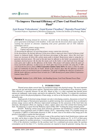
ELEMENT ,WT (kg) O2 used DRY PRODUCT
C= 0.55 0.55 x 8/3 = 1.47 0.55 x 11/3 = 2.017(CO2)
H2 = 0.035 0.035 x8 =0.28
O2 = 0.047 ----------------------
Total O2 = 1.75 kg
(i) Minimum weight of air needed for combustion =
= 1.75 x 100/23
Min. air = 7.61 Kg
Excess air supplied is about 10%
= 7.61 x 0.10
= 0.761 kg
Total air supplied for combustion = Min. air + Excess air
= 7.61 + 0.761
= 8.371 Kg
Weight of N2 in flue gases
= 8.371 x 77/100
= 6.44 kg
Minimum weight of air needed = (1.75-0.047) x 100/23
= 7.404 Kg
WEIGHT OF DRY FLUE GASES PER KG OF COAL PER HR:
Name of gas Volume per m3
of
DFG
(x)
Molecular wt
(y)
Relative volume
Z= xy
Wt. per kg of DFG
Z=Z/ ∑Z
CO2 0.12 44 5.28 0.1746
CO 0.007 28 0.196 0.00648
N2 0.795 28 22.26 0.7364
O2 0.078 32 2.496 0.08257
∑Z = 30.23
Amount of carbon present per kg of gases=
Amount of carbon in 0.1746 kg of CO2 + Amount of carbon in 0.00648 kg of CO
= 3/11 x 0.1746 + 3/7 x 0.00648
= 0.04762 + 0.00278
= 0.0504 kg
Also,
Carbon in coal = 0.55 kg
Weight of DFG per kg of coal/hr
= [wt of C in 1 kg of coal] / [wt of C in 1 kg of flue gas]
= 0.55 / 0.0504
= 10.91 kg
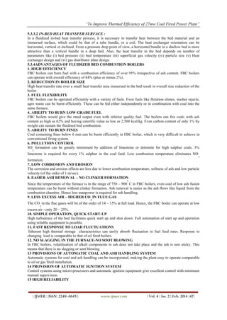
Weight of excess oxygen per kg of DFG
= 0.09524 - 4/7 x 0.00648
= 0.09524 – 0.0037
= 0.9154 kg [allowing for unburnt carbon monoxide]
Weight of excess oxygen = 10.91 x 0.09154
= 0.9987 ≈1 kg
Weight of excess air = 1 x 100/23
Weight of excess air= 4.35 kg
OVERALL PLANT EFFICIENCY :
At full load on turbine =24330 kW ,& total coal burnt = 20082 kg/hr
Total mass of coal = 47458 +9216 =20082 Kg/hr
ηoverall =
𝑜𝑢𝑡𝑝𝑢𝑡 𝑜𝑓 𝑠𝑡𝑎𝑡𝑖𝑜𝑛 𝑥 860
𝑐𝑜𝑎𝑙 𝑏𝑢𝑟𝑛𝑡 𝑋 𝑐𝑣 𝑜𝑓 𝑐𝑜𝑎𝑙
X100
23. “To Improve Thermal Efficiency of 27mw Coal Fired Power Plant”
| IJMER | ISSN: 2249–6645 | www.ijmer.com | Vol. 4 | Iss. 2 | Feb. 2014 |57|
ηoverall =
24330 𝑋860
20082 𝑋 3960
X100
𝜂overall = 26.31 %
Where 860 is the conversion factor which makes both numerator & denominator in same unit
But in the Birla Corporation Limited 27MW Thermal power Plant
Power generation is 24330 KW
Total coal burnt = 20082 – (472+390)
= 20082 - 862
mf = 19220 kg/hr
ηoverall =
𝑜𝑢𝑡𝑝𝑢𝑡 𝑜𝑓 𝑠𝑡𝑎𝑡𝑖𝑜𝑛 𝑥 860
𝑐𝑜𝑎𝑙 𝑏𝑢𝑟𝑛𝑡 𝑋 𝑐𝑣 𝑜𝑓 𝑐𝑜𝑎𝑙
X100
𝜂overall =
24330 𝑋 860
20082 𝑋3960
X100
𝜂overall l =
20923800
79409880
X100
𝜂overall =26.34%
MODIFICATION:
For Boiler No. 1
Total combustion of coal = 10866 - (unburnt coal X 0.01)
mf = 10866 – (472 x 0.01)
mf = 10866 – 47.2
mf =10861.287 kg/hr
Increases in boiler efficiency
ηboiler =
𝑚𝑠 (ℎ𝑠𝑢𝑝 −ℎ𝑓1)
𝑚𝑓 𝑋 𝐶𝑉 𝑜𝑓 𝑐𝑜𝑎𝑙
X100
ηboiler =
55958 (3390.5−786.59)
10861 .287𝑋 16568 .64
X100
ηboiler =
145709595 .78
179956638 .3
X100
ηboiler = 80.96 %
Increase s in boiler (1) efficiency
Increase s in boiler efficiency= 80.96 - 80.93
Increases in boiler (1) efficiency=0.03% to 0.06%
Incresease in efficiency upto 0.03 % to 0.06%
In Boiler No. 2
Total combustion of coal = 9216 - (unburnt coal X 0.01)
mf = 9216 – (390 x 0.01)
mf = 9216 – 3.9
mf =9212.1 kg/hr
Increases in boiler efficiency
ηboiler =
𝑚𝑠 (ℎ𝑠𝑢𝑝 −ℎ𝑓1)
𝑚𝑓 𝑋 𝐶𝑉 𝑜𝑓 𝑐𝑜𝑎𝑙
X 100
ηboiler =
47458 (3390.5−786.59)
9212.1 𝑋 16568 .64
X 100
ηboiler =
123576360 .8
152631968 .5
X 100
ηboiler = 80.96 %
Increase s in boiler (2) efficiency:
Increase s in boiler efficiency= 80.96 - 80.93
Increases in boiler (2) efficiency=0.03% to 0.06%
INCREASES IN OVERALL PLANT EFFICINCY
24. “To Improve Thermal Efficiency of 27mw Coal Fired Power Plant”
| IJMER | ISSN: 2249–6645 | www.ijmer.com | Vol. 4 | Iss. 2 | Feb. 2014 |58|
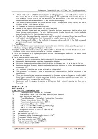
𝜂overall =
𝑜𝑢𝑡𝑝𝑢𝑡 𝑜𝑓 𝑠𝑡𝑎𝑡𝑖𝑜𝑛 𝐾𝑊 𝑥 860
𝑐𝑜𝑎𝑙 𝑏𝑢𝑟𝑛𝑡 𝑥 𝐶𝑉 𝑜𝑓 𝑐𝑜𝑎𝑙
X100
𝜂overall =
24330 𝑥 860
20073 .38 𝑋 3960
X 100
𝜂overall =
20923800
79490584 .8
X 100
𝜼overall = 26.32%
Increase in Overall plant Efficiency in %
increase in overall efficiency= 26.32 – 26.31
increase in overall plant efficiency= 0.01% to 0.02%
RESULT & DISCUSSION
RESULT:
(1) Efficiency of boiler (1) = 80.93%
(2) Efficiency of boiler (2) = 80.93 %
(3) Overall plant efficiency = 26.31 %
After modification
(1) Efficiency of boiler (1) = 80.93% to 80.99%
(2) Efficiency of boiler (2) = 80.93 % to 80.99%
(3) Overall plant efficiency = 26.31 % to 26.32%
Increase in boiler efficiency is from 0.03 to 0.06%
Increases in overall plant efficiency is 0.01 % to 0.02%
DISCUSSION :
If the excesses air supplied is very large amount then the ignition temperature required for combustion of coal
is decrease which effect the combustion efficiency of coal is reduced and due to this losses in boiler is
maximized & formation of carbon monoxide is increase. So quantity of excess air is to maintained. And furnace
draft pressure is also effect the combustion of coal. The furnace draft pressure is maintained about the balanced
draft.
REFERENCES
[1]. Thermal Power Technology By Dr. V.K. Sethi , First Edition, Chapter3 page no. 23,chapter no. 4,page no.53,
[2]. Energy Conversion System –I, By Bhupendra Gupta, Second Edition Chapter No. 1, page no. 5, page no. 17
[3]. Thermal Engg. By R.K. Rajput, chapter no. 10,page no.496,chapter no.11 page no.555, page no. 558,chapter no.
12,page no. 580, page no. 583
[4]. Power plant Technology by G.D. Rai, edition third(2003), chapter no. 7 page no.241,page no.246 ,chapter no. 3, page
no. 193,page no. 207
[5]. www.birlacorporationlimited.com/27mwtppsatna, paragraph 3
[6]. Data from 27MW thermal power plant of BCL, satna
[7]. Bullock, A., 2010, Ash Handling: Why Dry Bottoms are better than Wet Bottoms, Power-Gen Worldwide, May 1.
[8]. NETL, 2009c, Opportunities to Improve the Efficiency of Existing Coal‐Fired Power Plants, Workshop Report, July
15–16.
[9]. Congressional Research Service, Increasing Efficiency of Coal‐Fired Power Plants, Richard J. Campbell, December
20, 2013
Topper, J. (2011), Status of Coal Fired Power Plants ,World-Wide, Joint IEA-CEA Workshop on High Efficiency,
Low Emission (HELE) Roadmap, New Delhi, India, 29 November,
www.iea.org/media/workshops/2011/cea/Topper.pdf
[10]. Energy Analysis and Efficiency Improvement of a Coal Fired Thermal Power Plant By R. Mahamud, M.M.K. Khan,
M.G. Rasul and M.G. Leinster.