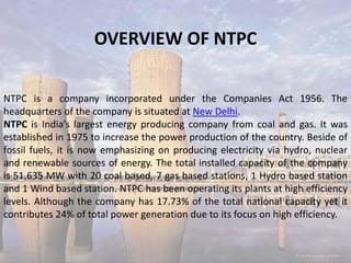
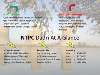
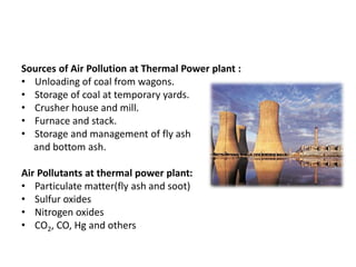
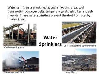
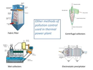
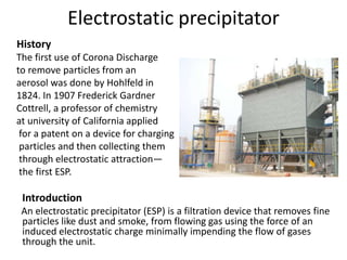
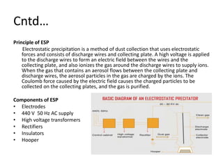
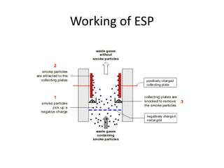
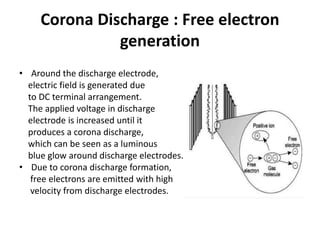
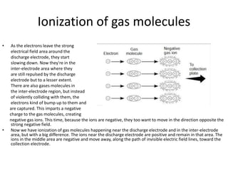
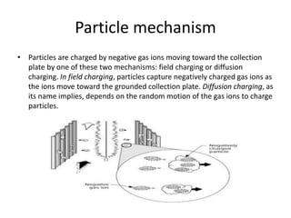
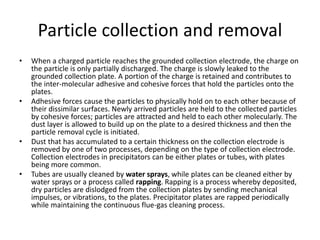
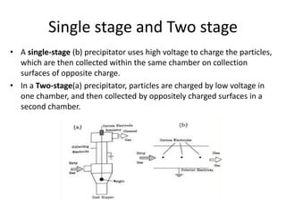
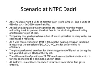
NTPC Dadri is a coal and gas-fired power station located in India. It has a total installed capacity of 2,642 MW from coal, gas, and solar power. An electrostatic precipitator (ESP) is used to remove particulate pollutants from the flue gases of thermal power plants like NTPC Dadri. An ESP works by charging particles using corona discharge and collecting them on oppositely charged plates. Periodically, the collected particles are removed from the plates through rapping or water spraying to maintain continuous cleaning of the flue gases.
Steam turbines and its associated systems(ntpc ramagundam)abdul mohammad
Steam turbine is an excellent prime mover to convert heat energy of steam to mechanical energy. Of all heat engines and prime movers the steam turbine is nearest to the ideal and it is widely used in power plants and in all industries where power is needed for process.
In power generation mostly steam turbine is used because of its greater thermal efficiency and higher power-to-weight ratio. Because the turbine generates rotary motion, it is particularly suited to be used to drive an electrical generator – about 80% of all electricity generation in the world is by use of steam turbines.
Rotor is the heart of the steam turbine and it affects the efficiency of the steam turbine. In this project we have mainly discussed about the working process of a steam turbine. The thermal efficiency of a steam turbine is much higher than that of a steam engine.
The document provides an overview of a coal-based thermal power plant presented by Shivam Kumar. It describes the key components of the plant including the coal handling plant, boiler and auxiliaries like superheaters and economizers, condenser, cooling towers, feedwater heaters, turbines, deaerator, and electrostatic precipitator. The plant has a capacity of 1500MW in stage 1 and is located in Haryana, utilizing coal delivered by rail to generate electricity through the Rankine cycle process in its boilers and turbines.
The document describes the key components and processes involved in a typical coal-fired thermal power plant, including the boiler, turbine, condenser, coal handling equipment, and other auxiliary systems. It also provides diagrams to illustrate the general layout and flow of energy conversion from coal to steam to mechanical power to electricity. Additionally, it briefly mentions some major thermal power plants located in the state of Rajasthan, India.
The document discusses the ash handling system at NTPC Dadri power plant. It has three types of ash handling systems: bottom ash, air preheater ash, and fly ash. Bottom ash is collected in hoppers under the furnace and transported to ash ponds in slurry form after grinding. Fly ash is captured by the air preheater, economizer, and ESP and stored in silos. The ashes are then mixed with water to form slurry and pumped via pipelines to the ash disposal site. Proper ash handling is required as thermal power plants produce a large amount of ash as a byproduct of coal combustion.
The document describes the key systems and processes involved in a typical coal-based power plant. It discusses the various stages from receiving coal, to grinding and feeding it into the boiler to produce steam, to generating electricity via turbines connected to generators, and finally returning water to a liquid state to repeat the process. The power plant relies on integrated systems to handle coal, water, combustion, electricity production, ash removal and emissions control to efficiently and reliably generate power.
kota super thermal Power station training reportEr. Aman Agrawal
it is a practical training report on kota super thermal power station
For any other enquiry u can contact me on +919540278218....
and can join my Page www.facebook.com/engineeringindia
ppt on NTPC kahalgaon ,bhagalpur ( bihar) BY AKHILESH & PRIYESHAKHILESH KUMAR
This document provides an overview of a summer training presentation on the National Thermal Power Plant in Kahalgaon, Bihar, India. It was submitted by an engineering student to their professor. The presentation covers the plant's coal handling system, boiler and auxiliary systems, turbine system, ash handling system, and off-site maintenance departments. It includes descriptions of the equipment used in coal handling, the boiler maintenance department, turbine maintenance, and ash handling. It also provides background on NTPC, the company that operates the plant, and details on the plant's layout and specifications.
1. The presentation summarizes the key features of the Kota Super Thermal Power Station (KSTPS) located in Sakatpura, Kota. KSTPS has a total installed capacity of 1240 MW and uses coal as its primary fuel source.
2. The power station operates via five stages, with the first two units producing 110 MW each and subsequent units producing 210 MW and 195 MW. It utilizes various equipment for coal handling, crushing, pulverizing, steam generation, and power production.
3. KSTPS feeds power into the electrical grid through its switchyard, which includes components like isolators, lightning arresters, busbars, and transformers to handle and distribute the generated electricity
This document provides an overview of a thermal power station. It begins with defining a thermal power station as a generating station that converts the heat energy from coal combustion into electrical energy. It then outlines the main components of a thermal power station in a block diagram and lists the main equipment, including the coal handling plant, pulverizing plant, boiler, turbine, alternator, condenser, and cooling towers. Each of the major equipment is then explained in more detail. Finally, the document discusses the advantages of thermal power stations in being able to use cheap fuel and their disadvantages in polluting the atmosphere.
This document provides an overview of a coal handling plant (CHP). It discusses the key components and processes within a CHP, including:
- Transportation of coal primarily via railways to the plant.
- Analysis of incoming coal to check quality matches agreements.
- The general layout and flow of coal through the plant via wagon tipplers, conveyor belts, crushers, and bunkers.
- The crushing process uses a three stage system to reduce coal size.
- Operational cycles to bunker, stack, or reclaim coal depending on bunker levels and maintenance needs.
- Key equipment used includes wagon tipplers, conveyor belts, double roll crushers, rotary break
The document discusses the main components and working principle of a diesel generator. A diesel generator combines a diesel engine with an electric generator and other auxiliary devices to generate electrical energy. It works by converting the chemical energy of fuel into thermal energy, then mechanical energy through the combustion and expansion of gases in the engine, which is then converted into electrical energy through the generator via electromagnetic induction. The key components are the diesel engine, generator, and auxiliary devices like the cooling system. The diesel engine uses compression ignition to burn fuel injected into the combustion chamber.
A combined cycle power plant generates electricity in two stages. First, a gas turbine burns fuel to drive a generator and produce electricity, with the exhaust heat recovered. This waste heat is then used to create steam to drive a steam turbine and generate additional electricity. Combined cycle power plants can achieve efficiencies as high as 55% and produce up to 50% more electricity than traditional simple-cycle plants from the same fuel. They have advantages of higher efficiency, lower emissions, and ability to run on different fuels, but also have higher costs and are less responsive than other power plant types.
The document provides an overview of thermal power generation. It discusses the need for thermal power, the basic working principles, and classifications by fuel and prime mover. The key steps in the thermal power generation process include heating water to create steam, using the steam to power a turbine connected to a generator to produce electricity, and then condensing the steam to be reused. Thermal power plants have advantages of using widely available fuels but have lower efficiency and higher emissions than other generation methods. Improving plant efficiency and reducing emissions are important areas of ongoing research and development.
The document discusses achieving sustainability through high impact energy efficiency using solar rooftops. It notes that solar rooftops are achieving grid parity due to policy and regulatory support in states like Andhra Pradesh, Tamil Nadu, and Kerala. The document presents case studies on commercial and residential solar rooftop projects in various Indian states and finds internal rates of return for solar rooftop projects in Andhra Pradesh, Tamil Nadu, Karnataka, and Maharashtra to be in the range of 13-33% depending on the state and industry.
This document discusses coal handling plants (CHPs) at thermal power stations. It begins with an introduction to coal and its uses. It then discusses the objectives and general layout of a CHP, including receiving coal via various transportation methods, temporary coal storage, crushing equipment, conveying systems, and auxiliary equipment. Specific equipment like wagon tipplers, conveyor belts, crushers, and feeders are explained. The document concludes with discussing coal analysis, maintenance needs of a CHP, and references.
Thermal power plants generate electricity from heat and are classified by their fuel source. Nuclear power plants use nuclear fission, fossil fuel plants use coal, natural gas, or biomass, and geothermal plants extract steam from underground. The basic operation involves fuel being pulverized and burned to create steam, which spins a turbine connected to a generator. Coal power plants in particular convey and pulverize coal before burning it in a boiler to heat water and create steam to power the turbine generator. The steam then condenses and the water is recycled through the system in a continuous Rankine cycle to generate electricity efficiently from coal.
This document provides a summary of a seminar presentation about the main parts of a thermal power plant. The summary includes:
- An overview of the key components of a thermal power plant, including the coal handling plant, boiler, turbine generator, transformers, and switchyard.
- Descriptions of the main functions of the boiler, including converting coal energy into steam and heating feedwater and steam.
- Explanations of other important systems like the cooling tower, ash handling plant, water treatment plant, and their roles in the power generation process.
TPS training report Gandhinagar, coal base power plant vishal patel
This document provides an overview of a practical training report submitted by two students for their Bachelor of Engineering degree in Mechanical Engineering. It includes an introduction to the power plant where they conducted their training, describing its key components like the boiler, coal mill, draught system and more. Diagrams are provided to illustrate the typical processes used in a coal-fired thermal power station.
This document summarizes a student's study of the boiler system at the NTPC Ramagundam thermal power station in India. Key points:
- The study examines how coal is combusted in the boiler to generate high-pressure steam, which is then used to power turbines and generate electricity.
- The NTPC plant uses high-pressure water tube boilers fueled by pulverized coal. It can generate 2600MW of power through 7 generating units.
- Boiler components like water walls, drums, and superheaters are discussed. Steam is generated at high pressures and temperatures before powering turbines.
- Boiler reliability is critical but failures can occur due to issues like poor design
Thermal power plant Khedr, Hisar, HaryanaEesha Gupta
The document provides information about the Rajiv Gandhi Thermal Power Plant (RGTPP) in Khedar, India. It discusses that RGTPP has two units that generate 600 MW each for a total output of 1200 MW per day. It then describes the basic processes that occur in a coal-based thermal power plant, including how coal is converted to steam to drive turbines and generate electricity. The document outlines the major components of RGTPP, including the coal handling system, boiler, turbines, generators, cooling system and instrumentation.
This document discusses hydroelectric power generation. It begins by providing a brief history, noting that the first hydroelectric power plant began operating in 1882 in the US, while India's first was in 1902. Today hydroelectricity accounts for 21% of India's power and 30% globally.
It then explains the basic process of hydroelectric power generation - using water stored in dams to turn turbines that power generators. The next section lists the top 5 largest hydroelectric power plants in the world by capacity. Three Gorges Dam in China has the largest capacity at 22,500 MW.
The document concludes by discussing advantages such as low operating costs, and disadvantages including high initial costs and requiring plants to be located in
A thermal power station converts heat energy into electrical power by boiling water to produce steam that spins turbines connected to electrical generators. Water is heated in a boiler, turning it into high-pressure steam that drives the turbine, which turns a generator to produce electricity. After passing through the turbine, the steam is condensed back into water and recycled to be heated again in a closed loop system. Thermal power stations use various heat sources like coal, natural gas, nuclear reactions or solar thermal to produce the steam.
Bharat Heavy Electricals Limited (BHEL) is India's largest power equipment manufacturer and 12th largest globally. It has been in operation for over 50 years and has manufactured over 72% of India's total power generation capacity. BHEL exports products and services to over 70 countries. The document discusses BHEL's involvement in the 2x500 MW Durgapur Steel Thermal Power Station located in West Bengal, which it constructed on a turnkey basis for owner Damodar Valley Corporation. It then provides details on the power plant layout and components, including the boiler, turbine, generator, and cooling system.
Thermal Power Plant - Full Detail About Plant and Parts (Also Contain Animate...Shubham Thakur
A thermal power station is a power plant in which the prime mover is steam driven. Water is heated, turns into steam and spins a steam turbine which drives an electrical generator. After it passes through the turbine, the steam is condensed in a condenser and recycled to where it was heated; this is known as a Rankine cycle. The greatest variation in the design of thermal power stations is due to the different fossil fuel resources generally used to heat the water. Some prefer to use the term energy center because such facilities convert forms of heat energy into electrical energy.[1] Certain thermal power plants also are designed to produce heat energy for industrial purposes of district heating, or desalination of water, in addition to generating electrical power. Globally, fossil fueled thermal power plants produce a large part of man-made CO2 emissions to the atmosphere, and efforts to reduce these are varied and widespread.
For Video on Themal Power Plant (Animated Working Video) :- https://www.youtube.com/watch?v=ouWOhk1INjo
Subscribe To Our Youtube Channel For More Videos:-
https://www.youtube.com/TheEngineeringScienc
Click Here To Subscribe:-
http://www.youtube.com/user/TheEngineeringScienc?sub_confirmation=1
This document provides an overview of a thermal power plant. It begins with an introduction explaining that a thermal power plant converts the heat energy from coal into electrical energy. It then describes the main components of a thermal power plant including the coal handling plant, boiler, turbine, condenser, and cooling towers. The document also discusses the waste generated from thermal power plants and methods for controlling waste. Finally, it lists some of the key advantages and disadvantages of thermal power plants.
The document discusses points related to sub critical and super critical boiler design, including boiler design parameters, chemical treatment systems, operation, feedwater systems, boiler control, and startup curves. It provides explanations of sub critical and super critical boiler technologies, comparing drum type sub critical boilers to drumless super critical boilers. Key differences in operation and response to load changes are highlighted.
The document discusses condensers used in thermal power plants. It describes the functions of a condenser as condensing exhaust steam from turbines to be reused in the steam cycle, creating a vacuum to improve turbine efficiency, and removing non-condensable gases. Key aspects covered include the condenser's role in the Rankine cycle, operation, materials used for tubes, sources of air leakage, methods for detecting water leakage into tubes, and cleaning and testing of condenser tubes.
1.1 Layout of thermal power plant - merits and demerits of thermal power plant – pollutants - effects and control – cyclone separator – wet scrubber – electrostatic precipitator – control of No2 and SO2. - fluidised bed combustion.
4 solar refrigeration and elecricity generationMd Irfan Ansari
This document discusses refrigeration and solar energy conversion systems. It describes vapor compression and solar vapor absorption refrigeration cycles. It explains how photovoltaic cells work by converting solar radiation into electricity via the photoelectric effect. Key components of PV systems like solar panels, batteries, and inverters are outlined. Advantages and limitations of solar energy conversion are also summarized. Solar lanterns are provided as a simple application of solar PV technology for rural lighting needs.
Principle, MHD system, open cycle system, closed cycle
system, design problems & developments, advantages,
materials for MHD generators, magnetic field & super
conductivity
Secondary tar cleaning systems and technologiesAyisha586983
Physical separation process will continue to play a very important role for the successful commercial implementation of gasification.
Tar present in producer gas is removed mainly through wet or dry scrubbing, as it could be easily designed and applied depending on the specific need of any gasification process.
Even though in bed tar cracking is feasible in some cases removal of dust particles becomes necessary along with gas cooling
this is the report on Hydrogen Fuel cell. which is the future of vehicles & probably future of electric vehicles.
Hydrogen Fuel cell is the one part or type of fuel cell.
here is the working, advantages, disadvantages of fuel cell vehicles.
as well as there are list of popular fuel cell vehicles recently launched.
23-03-2020
The document discusses green energy sources such as solar and wind power. It notes two main problems with fossil fuels: they are finite and will run out, and their combustion produces polluting gases. It then provides information on various green energy technologies like solar thermal power, photovoltaics, wind turbines, and their advantages and disadvantages. Key green energy sources discussed include solar power, which can be used for daylight, drying crops, heating spaces and water, and generating electricity via concentrated solar power or photovoltaics. Wind power is also summarized, including the power density of wind at different heights and applications of wind turbines.
Atomic absorption spectroscopy measures the absorption of light by ground state atoms. It works by vaporizing a sample using a flame or graphite furnace atomizer and measuring the absorption of light from a hollow cathode lamp at a specific wavelength corresponding to the element of interest. Key components of an atomic absorption spectrometer include the radiation source, atomizer, monochromator, detector, and recorder. It can analyze over 60 elements and provides a sensitive technique for detecting metals in samples. Potential interferences include physical effects that alter nebulization or chemical effects that influence atomization.
The document discusses electrostatic precipitators (ESPs), which are devices that remove dust particles from gas streams using electrostatic forces. ESPs work by charging dust particles using corona discharge and attracting them to oppositely charged collection plates. Key components of an ESP include discharge electrodes, collection electrodes, a rectifier to convert AC to DC power, and a hopper to collect dust. Factors like gas velocity, ESP geometry, and particle residence time impact collection efficiency. ESPs are highly efficient filtration devices that allow gas flow while removing fine particulate matter like dust and smoke.
This document provides an overview of an electrostatic precipitator (ESP) used to remove dust particles from industrial exhaust gases. It discusses how ESPs work by using corona discharge to electrically charge particles, which are then attracted to oppositely charged collection plates. The document also outlines the construction of an ESP including discharge electrodes, collection plates, casing and hopper. It compares dry and wet ESP types and discusses factors that influence ESP performance such as particle size distribution and flue gas temperature.
Electrostatic precipitators and scrubbersNeel Porwal
An electrostatic precipitator (ESP) uses electrostatic forces to remove particles from gases. It works by charging particles as they pass through a corona, or glow zone, then collecting them on oppositely charged plates. ESPs are highly efficient, able to remove over 99% of particles down to 0.1 μm, while minimally slowing gas flow. They have high capital costs but lower maintenance costs than wet scrubbers.
MHD power generation directly converts heat into electricity using magnetohydrodynamics. Hot ionized gas is passed through a magnetic field, inducing a current due to the Lorentz force. There are two main types - open cycle systems that exhaust combustion products and closed cycle systems that recycle the working fluid like seeded inert gas or liquid metal. While more efficient than conventional power, MHD systems require very high temperatures and large magnets, making them expensive. They have applications in spacecraft, experiments, and defense.
A fuel cell converts chemical energy from hydrogen into electricity through an electrochemical reaction with oxygen. It requires a continuous fuel source unlike batteries. There are different types of fuel cells defined by their electrolyte. A fuel cell has an anode, cathode, electrolyte and catalyst. Protons pass through the electrolyte but not electrons, which provide the current. Fuel cells produce electricity and water as byproducts. Problems include hydrogen storage and distribution limitations which can be addressed using fuel reformers.
The document discusses the concept of a space elevator, which would consist of a cable anchored to Earth and extending over 60,000 miles into space. The cable would be made of carbon nanotubes and allow cheaper access to space than current rocket methods. Key components would include the ribbon, anchors on Earth and in space, initial spacecraft to deploy the ribbon, climbers to travel along the ribbon powered by lasers, and overcoming challenges like radiation, debris, and climber malfunctions. The space elevator could enable low-cost delivery of materials and people to space for activities like solar power satellites, space exploration, and telecommunications.
Ultraviolet (UV) radiation and microwaves can be used to initiate organic reactions. UV radiation provides enough energy to homolytically cleave bonds and generate free radicals to propagate reactions. Microwaves are used for heating through interactions with polar molecules. Mass spectrometry, nuclear magnetic resonance (NMR) spectroscopy, infrared (IR) spectroscopy, chromatography, and chemical tests are techniques used to analyze organic compounds and determine molecular structure.
This document provides information on various thin film deposition techniques used in nano electronics, including physical vapor deposition (PVD) methods like evaporation, sputtering, and ion plating. It also discusses chemical vapor deposition (CVD) and its types like atmospheric pressure CVD, low-pressure CVD, plasma-enhanced CVD, as well as epitaxy and molecular beam epitaxy (MBE). Other topics covered include ion implantation equipment and process, radiation damage from implantation, and formation of silicon oxide through thermal oxidation.
Fuel cells convert chemical energy directly into electrical energy through electrochemical reactions. They have various applications including powering vehicles, portable power and stationary power generation. There are several types of fuel cells classified based on electrolyte used such as PEMFC, DMFC, PAFC, MCFC and SOFC. Fuel cells have advantages like high efficiency, reliability and reduced emissions. However, fuel cells also have disadvantages like high manufacturing costs and lack of hydrogen infrastructure currently.
This document discusses direct energy conversion through photovoltaic cells and fuel cells. It provides details on:
1) How photovoltaic cells convert solar energy into electrical energy through a module of approximately 30 cells producing around 15V and 1.5A of current. Applications include water pumping, commercial and residential power, and consumer electronics.
2) What fuel cells are, how they convert hydrogen and oxygen into water and electricity through electrochemical reactions. Types are classified by temperature and electrolyte used, with hydrogen-oxygen and fossil fuel cells discussed in detail.
3) Advantages of fuel cells include high efficiency and low emissions, while disadvantages include higher costs and difficulties with hydrogen production and storage.
Similar to presentation on one month summer training at NTPC Dadri (20)
Presented by The Global Peatlands Assessment: Mapping, Policy, and Action at GLF Peatlands 2024 - The Global Peatlands Assessment: Mapping, Policy, and Action
Optimizing Post Remediation Groundwater Performance with Enhanced Microbiolog...Joshua Orris
Results of geophysics and pneumatic injection pilot tests during 2003 – 2007 yielded significant positive results for injection delivery design and contaminant mass treatment, resulting in permanent shut-down of an existing groundwater Pump & Treat system.
Accessible source areas were subsequently removed (2011) by soil excavation and treated with the placement of Emulsified Vegetable Oil EVO and zero-valent iron ZVI to accelerate treatment of impacted groundwater in overburden and weathered fractured bedrock. Post pilot test and post remediation groundwater monitoring has included analyses of CVOCs, organic fatty acids, dissolved gases and QuantArray® -Chlor to quantify key microorganisms (e.g., Dehalococcoides, Dehalobacter, etc.) and functional genes (e.g., vinyl chloride reductase, methane monooxygenase, etc.) to assess potential for reductive dechlorination and aerobic cometabolism of CVOCs.
In 2022, the first commercial application of MetaArray™ was performed at the site. MetaArray™ utilizes statistical analysis, such as principal component analysis and multivariate analysis to provide evidence that reductive dechlorination is active or even that it is slowing. This creates actionable data allowing users to save money by making important site management decisions earlier.
The results of the MetaArray™ analysis’ support vector machine (SVM) identified groundwater monitoring wells with a 80% confidence that were characterized as either Limited for Reductive Decholorination or had a High Reductive Reduction Dechlorination potential. The results of MetaArray™ will be used to further optimize the site’s post remediation monitoring program for monitored natural attenuation.
Kinetic studies on malachite green dye adsorption from aqueous solutions by A...Open Access Research Paper
Water polluted by dyestuffs compounds is a global threat to health and the environment; accordingly, we prepared a green novel sorbent chemical and Physical system from an algae, chitosan and chitosan nanoparticle and impregnated with algae with chitosan nanocomposite for the sorption of Malachite green dye from water. The algae with chitosan nanocomposite by a simple method and used as a recyclable and effective adsorbent for the removal of malachite green dye from aqueous solutions. Algae, chitosan, chitosan nanoparticle and algae with chitosan nanocomposite were characterized using different physicochemical methods. The functional groups and chemical compounds found in algae, chitosan, chitosan algae, chitosan nanoparticle, and chitosan nanoparticle with algae were identified using FTIR, SEM, and TGADTA/DTG techniques. The optimal adsorption conditions, different dosages, pH and Temperature the amount of algae with chitosan nanocomposite were determined. At optimized conditions and the batch equilibrium studies more than 99% of the dye was removed. The adsorption process data matched well kinetics showed that the reaction order for dye varied with pseudo-first order and pseudo-second order. Furthermore, the maximum adsorption capacity of the algae with chitosan nanocomposite toward malachite green dye reached as high as 15.5mg/g, respectively. Finally, multiple times reusing of algae with chitosan nanocomposite and removing dye from a real wastewater has made it a promising and attractive option for further practical applications.
Improving the viability of probiotics by encapsulation methods for developmen...Open Access Research Paper
The popularity of functional foods among scientists and common people has been increasing day by day. Awareness and modernization make the consumer think better regarding food and nutrition. Now a day’s individual knows very well about the relation between food consumption and disease prevalence. Humans have a diversity of microbes in the gut that together form the gut microflora. Probiotics are the health-promoting live microbial cells improve host health through gut and brain connection and fighting against harmful bacteria. Bifidobacterium and Lactobacillus are the two bacterial genera which are considered to be probiotic. These good bacteria are facing challenges of viability. There are so many factors such as sensitivity to heat, pH, acidity, osmotic effect, mechanical shear, chemical components, freezing and storage time as well which affects the viability of probiotics in the dairy food matrix as well as in the gut. Multiple efforts have been done in the past and ongoing in present for these beneficial microbial population stability until their destination in the gut. One of a useful technique known as microencapsulation makes the probiotic effective in the diversified conditions and maintain these microbe’s community to the optimum level for achieving targeted benefits. Dairy products are found to be an ideal vehicle for probiotic incorporation. It has been seen that the encapsulated microbial cells show higher viability than the free cells in different processing and storage conditions as well as against bile salts in the gut. They make the food functional when incorporated, without affecting the product sensory characteristics.
Microbial characterisation and identification, and potability of River Kuywa ...Open Access Research Paper
Water contamination is one of the major causes of water borne diseases worldwide. In Kenya, approximately 43% of people lack access to potable water due to human contamination. River Kuywa water is currently experiencing contamination due to human activities. Its water is widely used for domestic, agricultural, industrial and recreational purposes. This study aimed at characterizing bacteria and fungi in river Kuywa water. Water samples were randomly collected from four sites of the river: site A (Matisi), site B (Ngwelo), site C (Nzoia water pump) and site D (Chalicha), during the dry season (January-March 2018) and wet season (April-July 2018) and were transported to Maseno University Microbiology and plant pathology laboratory for analysis. The characterization and identification of bacteria and fungi were carried out using standard microbiological techniques. Nine bacterial genera and three fungi were identified from Kuywa river water. Clostridium spp., Staphylococcus spp., Enterobacter spp., Streptococcus spp., E. coli, Klebsiella spp., Shigella spp., Proteus spp. and Salmonella spp. Fungi were Fusarium oxysporum, Aspergillus flavus complex and Penicillium species. Wet season recorded highest bacterial and fungal counts (6.61-7.66 and 3.83-6.75cfu/ml) respectively. The results indicated that the river Kuywa water is polluted and therefore unsafe for human consumption before treatment. It is therefore recommended that the communities to ensure that they boil water especially for drinking.
Climate Change All over the World .pptxsairaanwer024
Climate change refers to significant and lasting changes in the average weather patterns over periods ranging from decades to millions of years. It encompasses both global warming driven by human emissions of greenhouse gases and the resulting large-scale shifts in weather patterns. While climate change is a natural phenomenon, human activities, particularly since the Industrial Revolution, have accelerated its pace and intensity
Epcon is One of the World's leading Manufacturing Companies.EpconLP
Epcon is One of the World's leading Manufacturing Companies. With over 4000 installations worldwide, EPCON has been pioneering new techniques since 1977 that have become industry standards now. Founded in 1977, Epcon has grown from a one-man operation to a global leader in developing and manufacturing innovative air pollution control technology and industrial heating equipment.
ENVIRONMENT~ Renewable Energy Sources and their future prospects.tiwarimanvi3129
This presentation is for us to know that how our Environment need Attention for protection of our natural resources which are depleted day by day that's why we need to take time and shift our attention to renewable energy sources instead of non-renewable sources which are better and Eco-friendly for our environment. these renewable energy sources are so helpful for our planet and for every living organism which depends on environment.
Recycling and Disposal on SWM Raymond Einyu pptxRayLetai1
Increasing urbanization, rural–urban migration, rising standards of living, and rapid development associated with population growth have resulted in increased solid waste generation by industrial, domestic and other activities in Nairobi City. It has been noted in other contexts too that increasing population, changing consumption patterns, economic development, changing income, urbanization and industrialization all contribute to the increased generation of waste.
With the increasing urban population in Kenya, which is estimated to be growing at a rate higher than that of the country’s general population, waste generation and management is already a major challenge. The industrialization and urbanization process in the country, dominated by one major city – Nairobi, which has around four times the population of the next largest urban centre (Mombasa) – has witnessed an exponential increase in the generation of solid waste. It is projected that by 2030, about 50 per cent of the Kenyan population will be urban.
Aim:
A healthy, safe, secure and sustainable solid waste management system fit for a world – class city.
Improve and protect the public health of Nairobi residents and visitors.
Ecological health, diversity and productivity and maximize resource recovery through the participatory approach.
Goals:
Build awareness and capacity for source separation as essential components of sustainable waste management.
Build new environmentally sound infrastructure and systems for safe disposal of residual waste and replacing current dumpsites which should be commissioned.
Current solid waste management situation:
The status.
Solid waste generation rate is at 2240 tones / day
collection efficiently is at about 50%.
Actors i.e. city authorities, CBO’s , private firms and self-disposal
Current SWM Situation in Nairobi City:
Solid waste generation – collection – dumping
Good Practices:
• Separation – recycling – marketing.
• Open dumpsite dandora dump site through public education on source separation of waste, of which the situation can be reversed.
• Nairobi is one of the C40 cities in this respect , various actors in the solid waste management space have adopted a variety of technologies to reduce short lived climate pollutants including source separation , recycling , marketing of the recycled products.
• Through the network, it should expect to benefit from expertise of the different actors in the network in terms of applicable technologies and practices in reducing the short-lived climate pollutants.
Good practices:
Despite the dismal collection of solid waste in Nairobi city, there are practices and activities of informal actors (CBOs, CBO-SACCOs and yard shop operators) and other formal industrial actors on solid waste collection, recycling and waste reduction.
Practices and activities of these actor groups are viewed as innovations with the potential to change the way solid waste is handled.
CHALLENGES:
• Resource Allocation.
Wildlife-AnIntroduction.pdf so that you know more about our environment
presentation on one month summer training at NTPC Dadri
1. Presentation on one month summer
training at NTPC Dadri
Presented by :
Raghav Dagar
MSCE-596-2K16
Working of Electrostatic Precipitator at
NTPC Dadri
2. OVERVIEW OF NTPC
NTPC is a company incorporated under the Companies Act 1956. The
headquarters of the company is situated at New Delhi.
NTPC is India’s largest energy producing company from coal and gas. It was
established in 1975 to increase the power production of the country. Beside of
fossil fuels, it is now emphasizing on producing electricity via hydro, nuclear
and renewable sources of energy. The total installed capacity of the company
is 51,635 MW with 20 coal based, 7 gas based stations, 1 Hydro based station
and 1 Wind based station. NTPC has been operating its plants at high efficiency
levels. Although the company has 17.73% of the total national capacity yet it
contributes 24% of total power generation due to its focus on high efficiency.
3. NTPC Dadri At A Glance
NTPC Dadri Gets
Coal from Piparwar mines, Jharkhand
Gas from GAIL Hajira-Bijapur-
Jagdishpur (HBJ) pipeline
Water from Upper Ganges Canal
NTPC Dadri Distributes To
NCR, U.P, Uttrakhand,
Rajasthan, Delhi, Punjab,
Haryana, Himachal Pradesh,
J&K, Chandigarh & Indian
Railways
Commissioned
In 1991, NTPC Dadri has
three types of Thermal
Power Stations- Coal
based, Gas-fired and Solar.
Responsible
For providing power to
NCR. Hence named
National Capital Power
Station (NCPS)
Capacity
Coal - 820 MW
Gas - 817 MW
Solar - 005 MW
Total - 2642 MW
4. Sources of Air Pollution at Thermal Power plant :
• Unloading of coal from wagons.
• Storage of coal at temporary yards.
• Crusher house and mill.
• Furnace and stack.
• Storage and management of fly ash
and bottom ash.
Air Pollutants at thermal power plant:
• Particulate matter(fly ash and soot)
• Sulfur oxides
• Nitrogen oxides
• CO2, CO, Hg and others
5. Water
Sprinklers
Water sprinklers are installed at coal unloading area, coal
transporting conveyer belts, temporary yards, ash dikes and ash
mounds. These water sprinklers prevent the dust from coal by
making it wet.
Coal unloading area
Coal transporting conveyer belts
Temporary coal yard Ash dike
6. Fabric filter Centrifugal collectors
Wet collectors Electrostatic precipitator
Other methods of
pollution control
used in thermal
power plant
7. Emission Standards
Existing emission standards:
Power generation capacity PM Emission
• Less than 210MW 350 mg/Nm3
• 210MW or more 150 mg/Nm3
New Emission standards:- dated 07.12.2015
TPPs (units) installed before 31.12.2003
• PM 100 mg/Nm3
• SO2 600 mg/Nm3 (<500MW)
200 mg/Nm3 (≥500MW)
• NOx 600 mg/Nm3
• Mercury 0.03 mg/Nm3
TPPs (units) installed after 01.01.2004 upto 31.12.2016
• PM 50 mg/Nm3
• SO2 600 mg/Nm3 (<500MW)
200 mg/Nm3 (≥500MW)
• NOx 300 mg/Nm3
• Mercury 0.03 mg/Nm3
TPPs (units) to be installed from 01.01.2017
• PM 30 mg/Nm3
• SO2 100 mg/Nm3
• NOx 100 mg/Nm3
• Mercury 0.03 mg/Nm3
8. Electrostatic precipitator
History
The first use of Corona Discharge
to remove particles from an
aerosol was done by Hohlfeld in
1824. In 1907 Frederick Gardner
Cottrell, a professor of chemistry
at university of California applied
for a patent on a device for charging
particles and then collecting them
through electrostatic attraction—
the first ESP.
Introduction
An electrostatic precipitator (ESP) is a filtration device that removes fine
particles like dust and smoke, from flowing gas using the force of an
induced electrostatic charge minimally impending the flow of gases
through the unit.
9. Cntd…
Principle of ESP
Electrostatic precipitation is a method of dust collection that uses electrostatic
forces and consists of discharge wires and collecting plate. A high voltage is applied
to the discharge wires to form an electric field between the wires and the
collecting plate, and also ionizes the gas around the discharge wires to supply ions.
When the gas that contains an aerosol flows between the collecting plate and
discharge wires, the aerosol particles in the gas are charged by the ions. The
Coulomb force caused by the electric field causes the charged particles to be
collected on the collecting plates, and the gas is purified.
Components of ESP
• Electrodes
• 440 V 50 Hz AC supply
• High voltage transformers
• Rectifiers
• Insulators
• Hooper
11. Corona Discharge : Free electron
generation
• Around the discharge electrode,
electric field is generated due
to DC terminal arrangement.
The applied voltage in discharge
electrode is increased until it
produces a corona discharge,
which can be seen as a luminous
blue glow around discharge electrodes.
• Due to corona discharge formation,
free electrons are emitted with high
velocity from discharge electrodes.
12. Ionization of gas molecules
• As the electrons leave the strong
electrical field area around the
discharge electrode, they start
slowing down. Now they're in the
inter-electrode area where they
are still repulsed by the discharge
electrode but to a lesser extent.
There are also gases molecules in
the inter-electrode region, but instead
of violently colliding with them, the
electrons kind of bump up to them and
are captured. This imparts a negative
charge to the gas molecules, creating
negative gas ions. This time, because the ions are negative, they too want to move in the direction opposite the
strong negative field.
• Now we have ionization of gas molecules happening near the discharge electrode and in the inter-electrode
area, but with a big difference. The ions near the discharge electrode are positive and remain in that area. The
ions in the middle area are negative and move away, along the path of invisible electric field lines, toward the
collection electrode.
13. Particle mechanism
• Particles are charged by negative gas ions moving toward the collection
plate by one of these two mechanisms: field charging or diffusion
charging. In field charging, particles capture negatively charged gas ions as
the ions move toward the grounded collection plate. Diffusion charging, as
its name implies, depends on the random motion of the gas ions to charge
particles.
14. Particle collection and removal
• When a charged particle reaches the grounded collection electrode, the charge on
the particle is only partially discharged. The charge is slowly leaked to the
grounded collection plate. A portion of the charge is retained and contributes to
the inter-molecular adhesive and cohesive forces that hold the particles onto the
plates.
• Adhesive forces cause the particles to physically hold on to each other because of
their dissimilar surfaces. Newly arrived particles are held to the collected particles
by cohesive forces; particles are attracted and held to each other molecularly. The
dust layer is allowed to build up on the plate to a desired thickness and then the
particle removal cycle is initiated.
• Dust that has accumulated to a certain thickness on the collection electrode is
removed by one of two processes, depending on the type of collection electrode.
Collection electrodes in precipitators can be either plates or tubes, with plates
being more common.
• Tubes are usually cleaned by water sprays, while plates can be cleaned either by
water sprays or a process called rapping. Rapping is a process whereby deposited,
dry particles are dislodged from the collection plates by sending mechanical
impulses, or vibrations, to the plates. Precipitator plates are rapped periodically
while maintaining the continuous flue-gas cleaning process.
15. Types of Electrostatic Precipitator
On the basis of structure and design
• Tubular
• Plate
On the basis of method of charging
• Single stage
• Double stage
On the basis of temperature of operation
• Hot-side
• Cold-side
On the basis of removal of particles from collection surface
• Wet
• Dry
16. Tubular and plate
• Tubular precipitators consist of cylindrical collection electrodes (tubes) with discharge
electrodes (wires) located in the center of the cylinder. Dirty gas flows into the tubes,
where the particles are charged. The charged particles are then collected on the inside
walls of the tubes. Collected dust and/or liquid is removed by washing the tubes with
water sprays located directly above the tubes.
• Plate ESPs have wire, rigid-frame, or plate discharge electrodes. Dirty gas flows into a
chamber consisting of a series of discharge electrodes that are equally spaced along
the center line between adjacent collection plates. Charged particles are collected on
the plates as dust, which is periodically removed by rapping or water sprays.
Tubular type ESP
Plate type ESP
17. Single stage and Two stage
• A single-stage (b) precipitator uses high voltage to charge the particles,
which are then collected within the same chamber on collection
surfaces of opposite charge.
• In a Two-stage(a) precipitator, particles are charged by low voltage in
one chamber, and then collected by oppositely charged surfaces in a
second chamber.
18. Hot-side and Cold-side
• A Hot-side precipitator is located before the combustion air pre-heater in a
boiler. The flue gas temperature for hot-side precipitators is in the range of
320 to 420°C.The use of hot-side precipitators helps reduce corrosion and
hopper plugging.
• Cold-side ESPs have been used where the flue gas temperature is relatively
low ( ≤204°C) and can be used to remove fly ash from boilers that burn high
sulfur coal and also can effectively remove fly ash from boilers burning low-
sulfur coal with the addition of conditioning agents.
19. Wet and Dry
• Wet ESPs are used where the potential for explosion is high or when dust is very
sticky, corrosive, or has very high resistivity. In a circular-plate wet ESP, the circular
collection plates are sprayed with liquid continuously. The liquid provides the
electrical ground for attracting the particles and for removing them from the plates.
• Most electrostatic precipitators are operated Dry and use rappers to remove the
collected particulate matter. The term dry is used because particles are charged and
collected in a dry state and are removed by rapping as opposed to water washing
which is used with wet ESPs.
Wet type ESP
Dry type ESP
20. Scenario at NTPC Dadri
• At NTPC Dadri Plant 4 units of 210MW each (from 1991-94) and 2 units of
490MW each (in 2010) were installed.
• At coal unloading area water sprinkles are installed near the wagon
unloading track to prevent the dust flow in the air during the unloading
and transportation of coal.
• Temporary coal yards also have a line of water sprinklers to spray water on
coal heaps if required.
• As it was commissioned in 1991 it follows the existing emission limits but
it measures the emission of SO2, CO2, NOx, etc for determining its
efficiency.
• The plant performed excellent for the management of fly ash as during the
last year it disposed 205% of the fly ash.
• The all four units of plant have 24 ESPs each connected to 4 ducts which is
further connected to a common outlet in stack.
• All 24 ESpss in a unit are connected to furnace from where flue gas is
entered.
21. Cntd…
• ESPs of Dadri plant are of Plate, Dry, Hot and Two staged type ESPs.
• Id fans are there to create air pressure to carry the flue gas.
• The particulate matter deposit on the walls of electrostatic precipitator is
removed by the on and off action of hammer on the walls.
• Stack height of the plant is 225m and the sampling is done at a height of
110m to analyze continuous emission monitoring system which also
collects samples at intervals.
• Temperature of flue gas is maintained above 150˚C existing from stack
because SO will condense at low temperatures
• Real time emission data of 10th and 11th July of Dadri Plant
NOx SOx PM
10.07.2017 413.49 1020.68 42.11
11.07.2017 421.33 977.29 35.09
all emissions (on average of all stacks) are in milligram per
normal meter cube taken from NTPC Dadri