Downloaded 313 times


This document provides an overview of reservoir rock and fluid properties. It discusses key concepts such as porosity, permeability, fluid interactions, and reservoir drive mechanisms. Porosity refers to the void spaces in rock that can store hydrocarbons. Permeability measures how easily fluids can flow through rock. The document also examines factors that affect porosity and different types of porosity and permeability. Reservoir drive mechanisms like solution gas, gas cap, and water drives are explained. Finally, it briefly discusses secondary and tertiary recovery methods used to improve oil extraction rates.
Introduction to the module focusing on reservoir rock characteristics, porosity, permeability, and fluid interactions.
Key characteristics for hydrocarbons reservoirs include storage capacity and fluid transmissibility.
Porosity defines void space in rocks, ranging from 5% to 30%. Distinguishes total, effective, primary, and secondary porosity.
Permeability measures fluid flow ease in rocks, characterized in darcy units. Methods include liquid and gas permeameters.
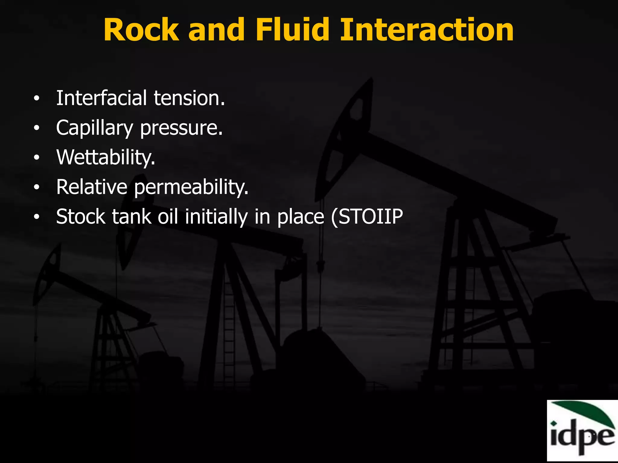
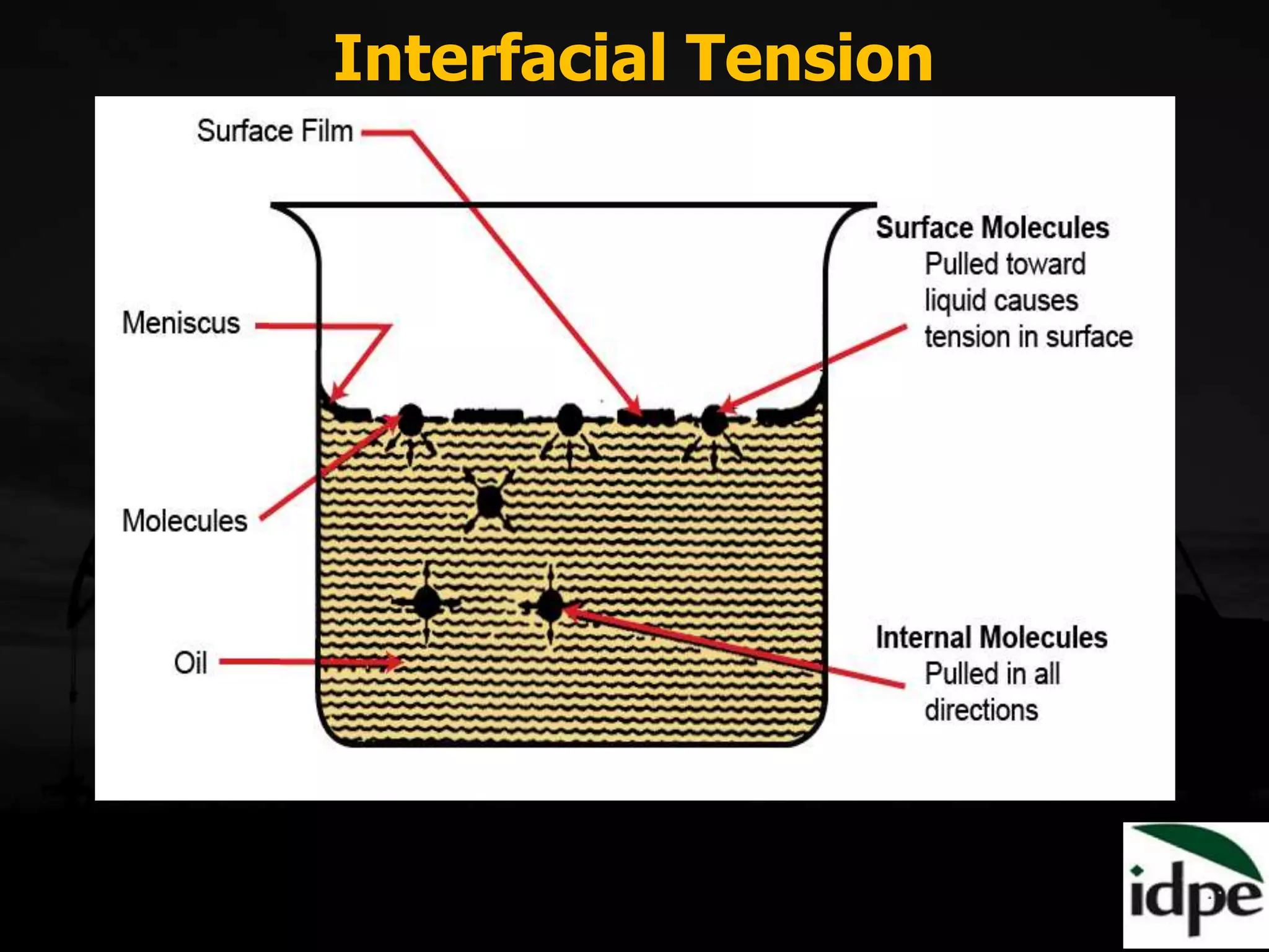
Interactions include interfacial tension and surface tension effects, relevant to fluid behavior in rocks.
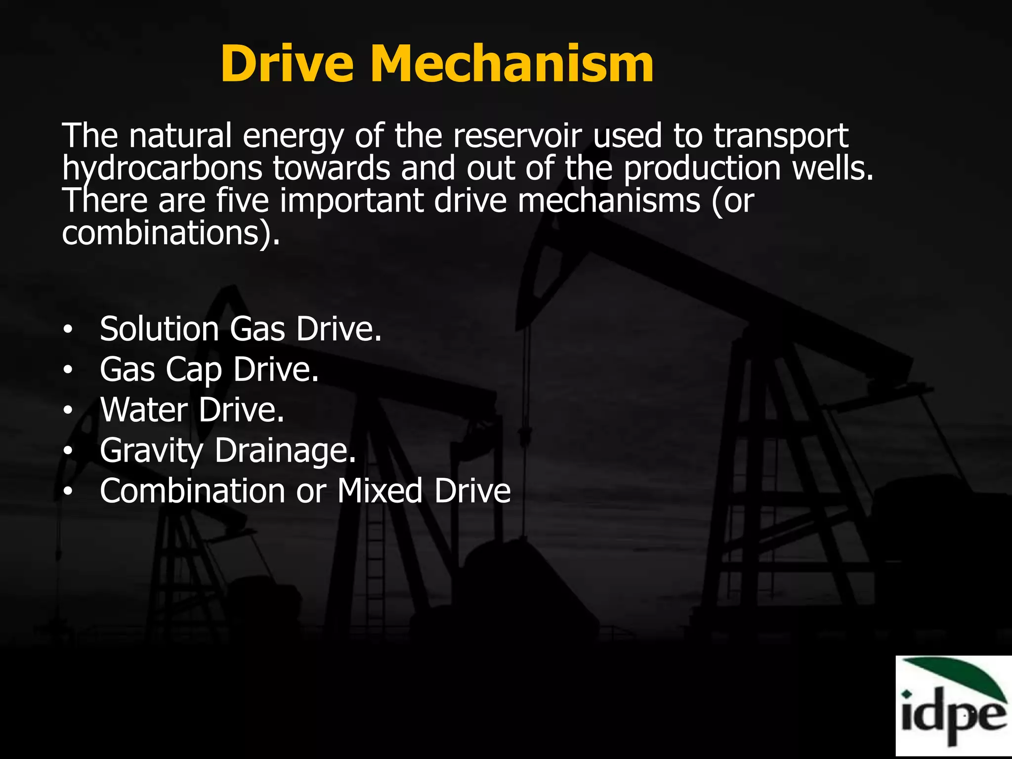
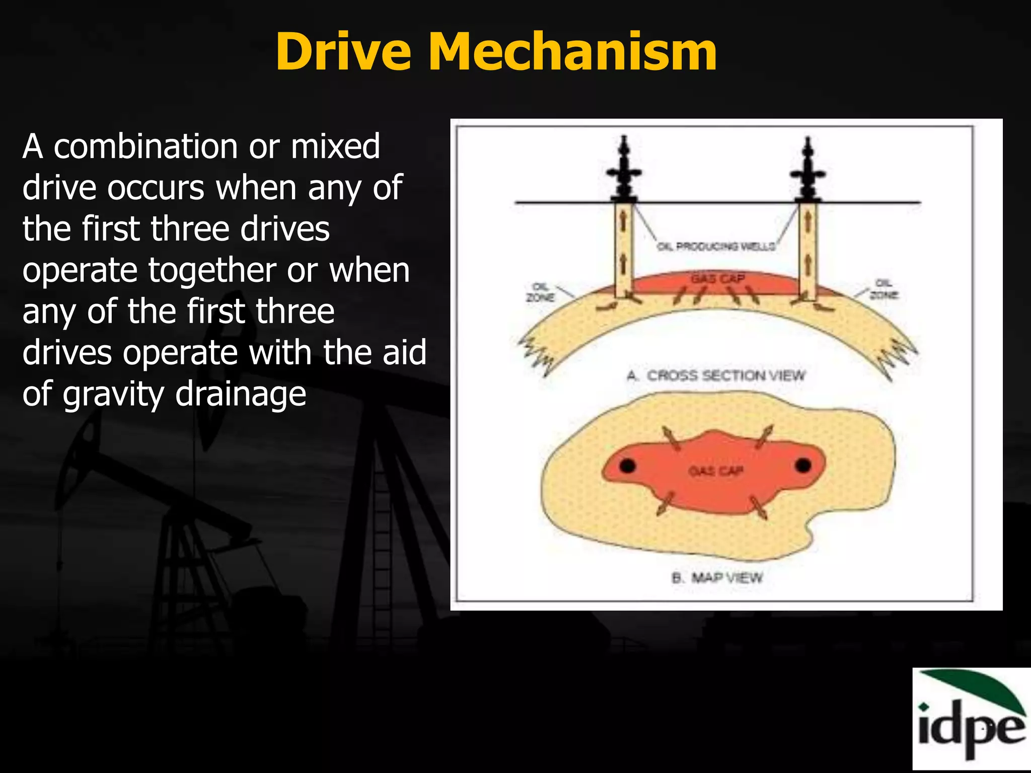
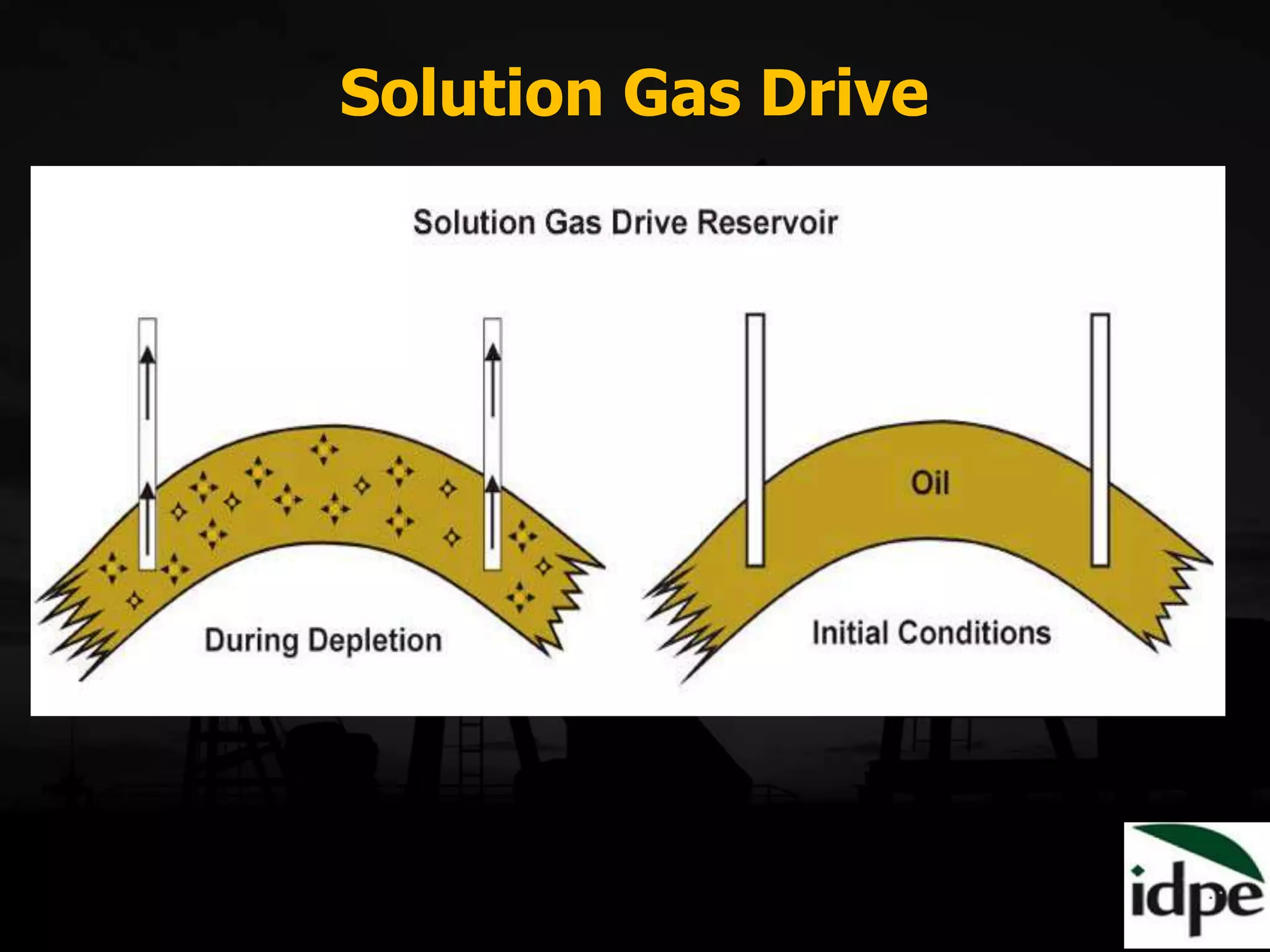
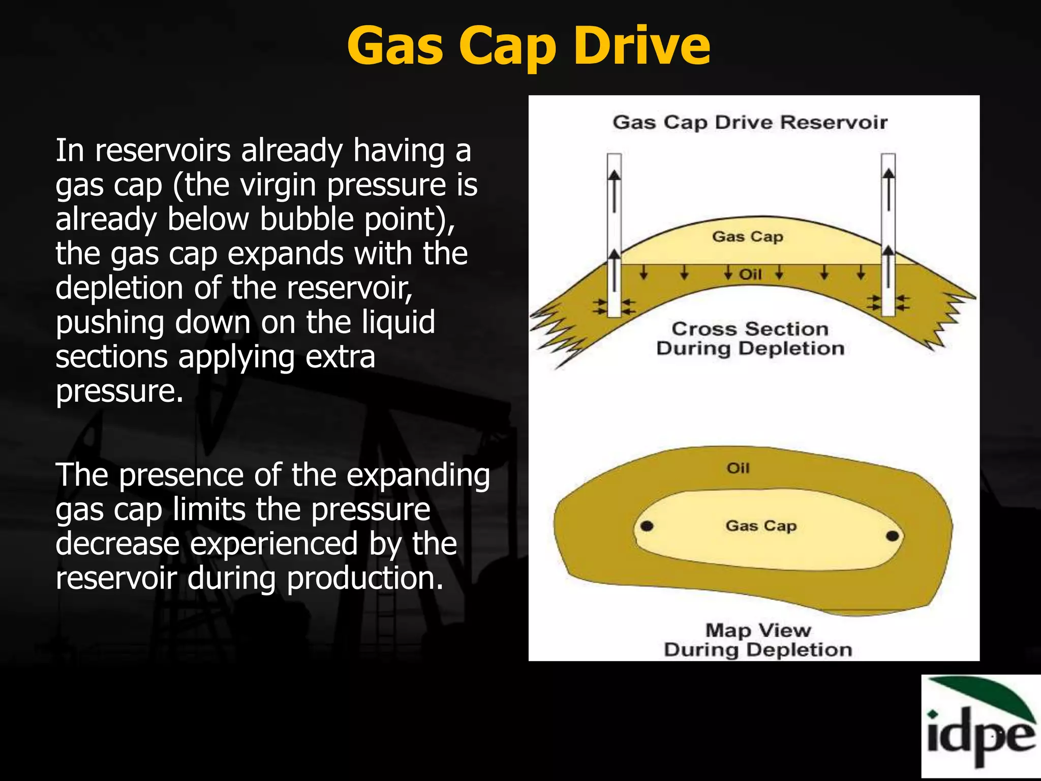
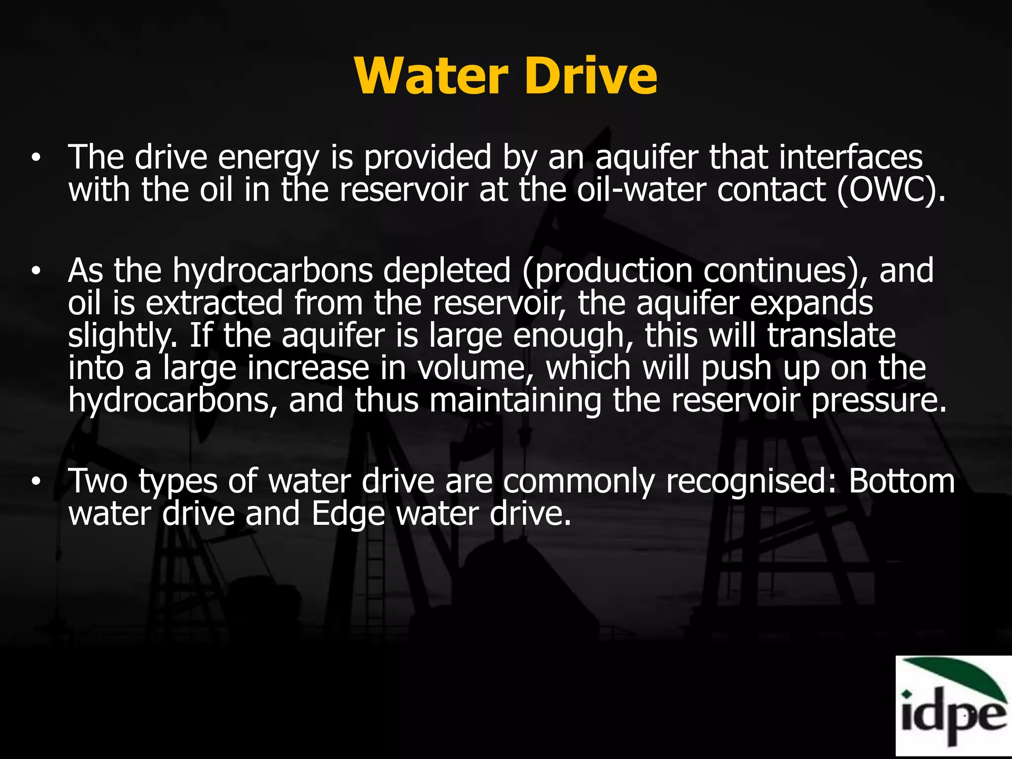
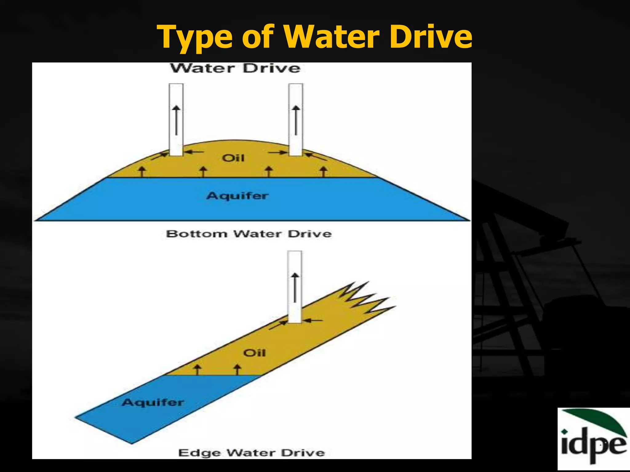
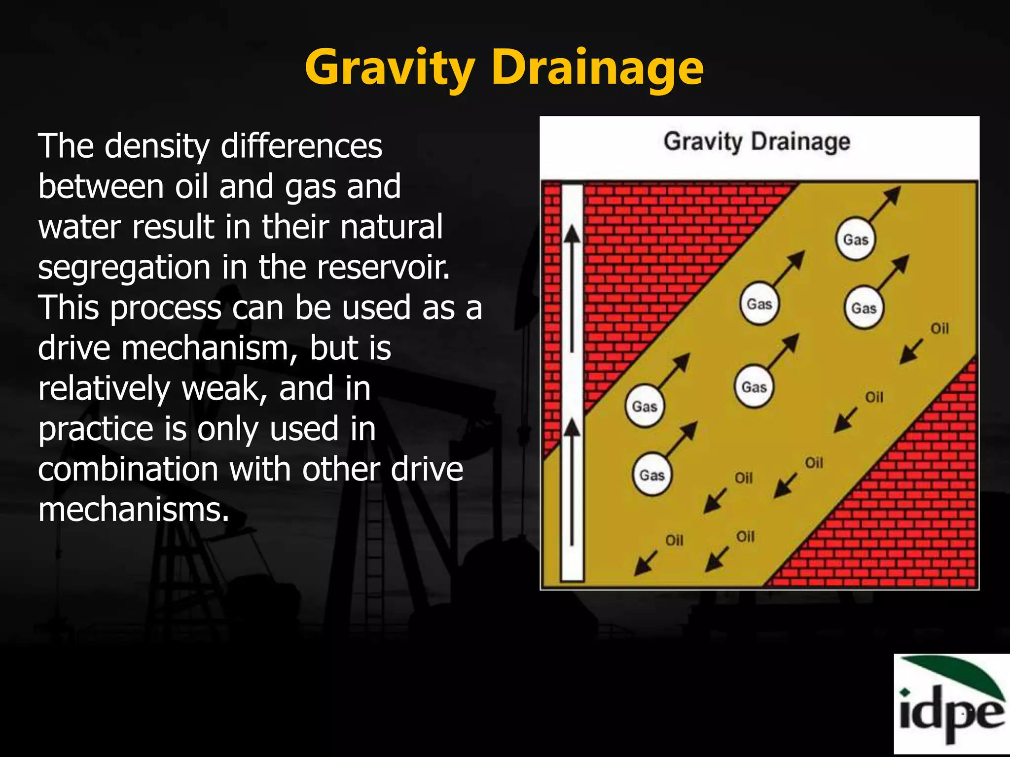
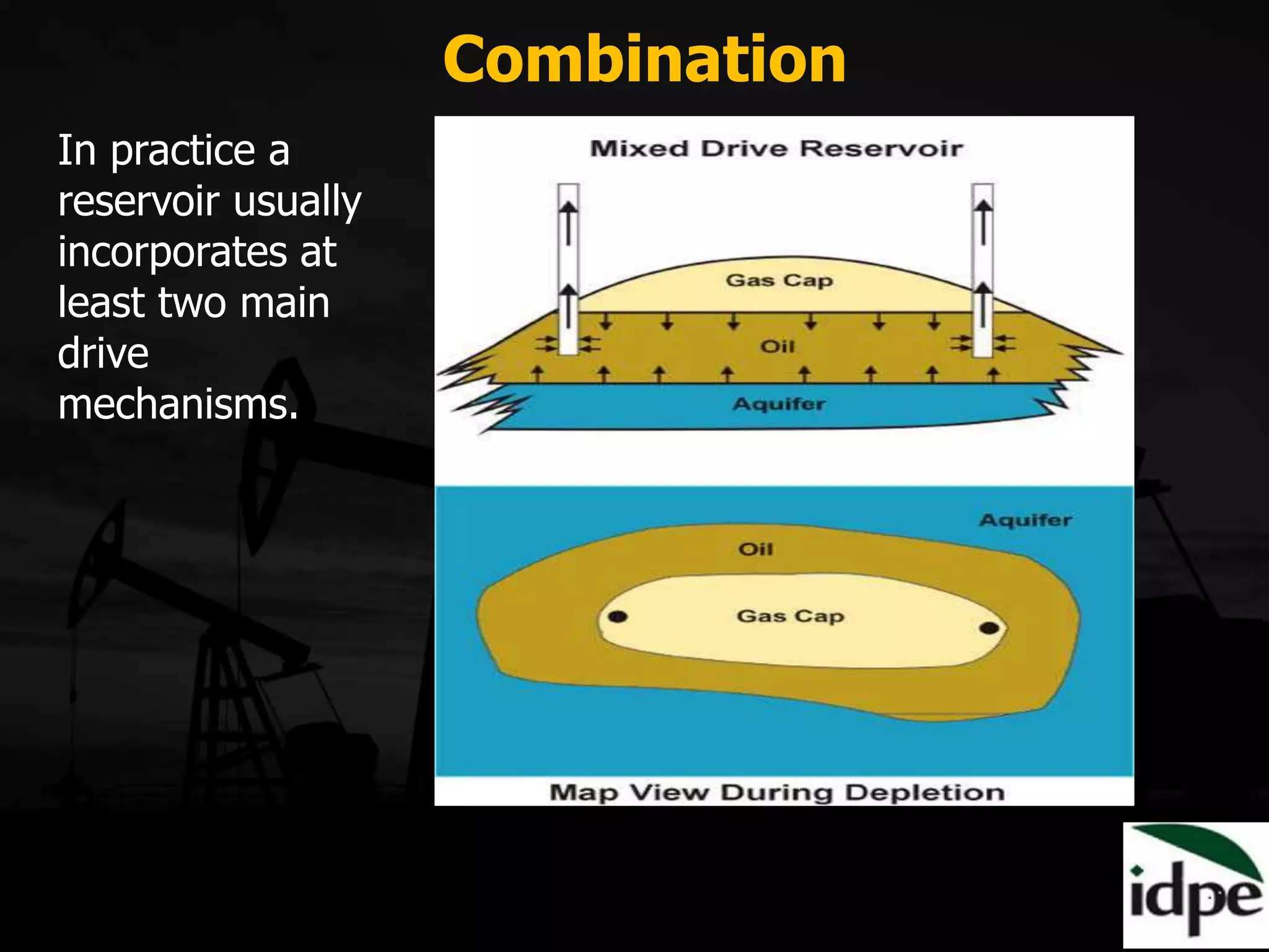
Mechanisms like solution gas drive, water drive, and gravity drainage inform hydrocarbon extraction strategies.
Secondary recovery uses water/gas injection for improved oil output, while tertiary methods (thermal, chemical, miscible gas) enhance recovery beyond 35%.