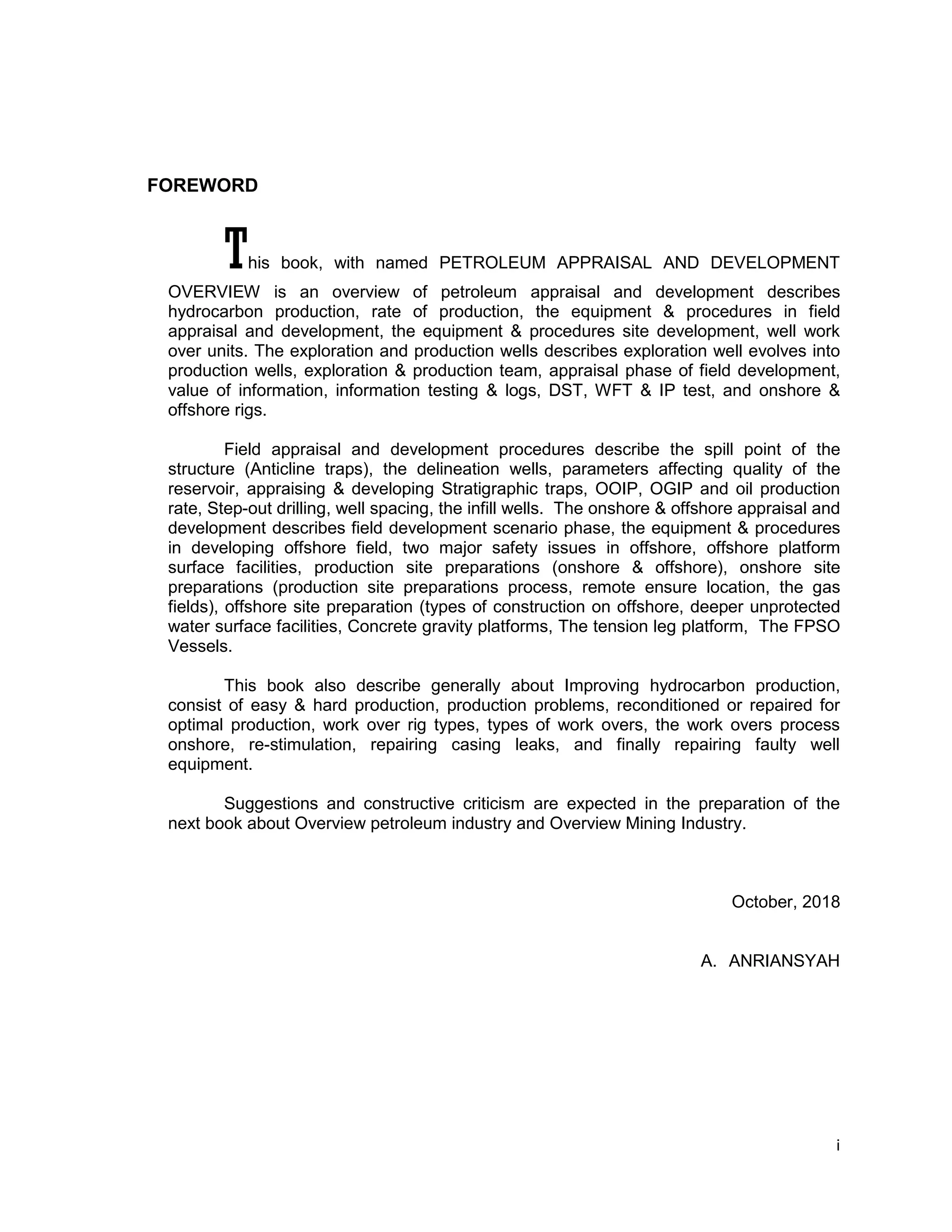
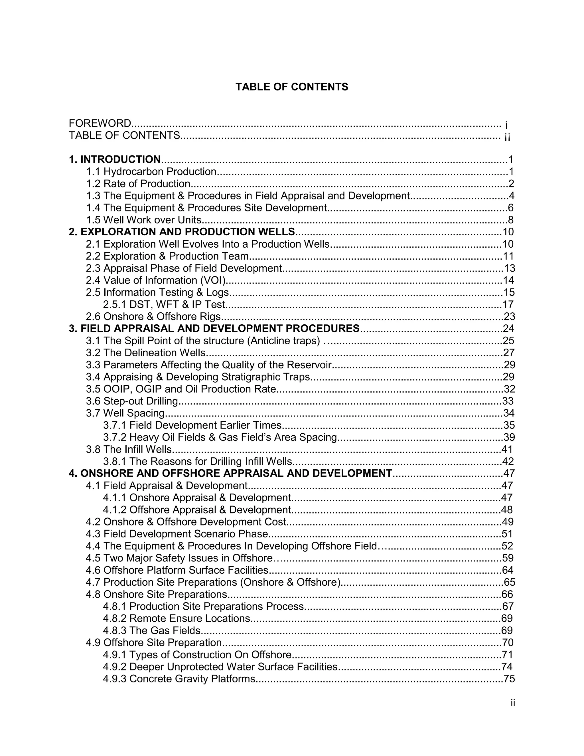
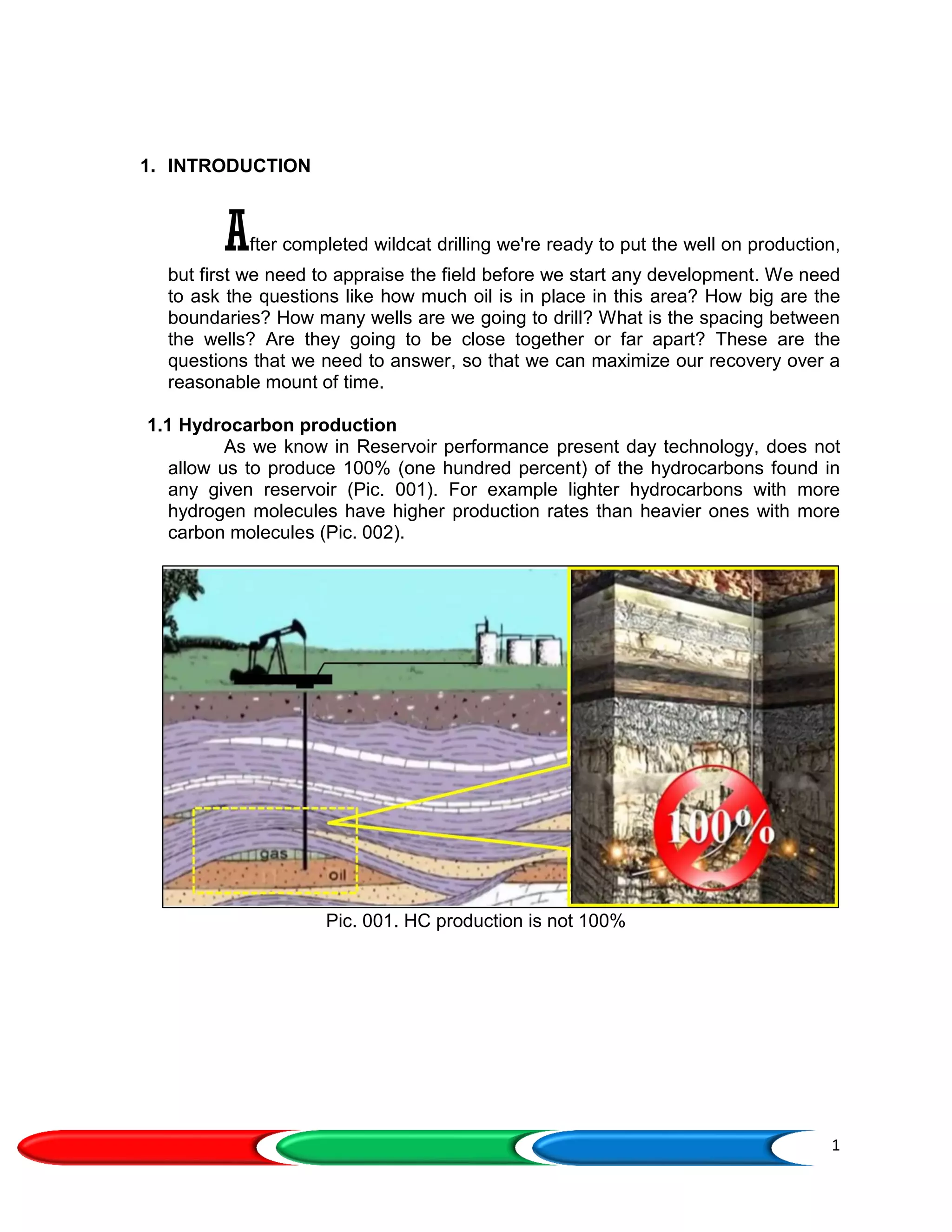
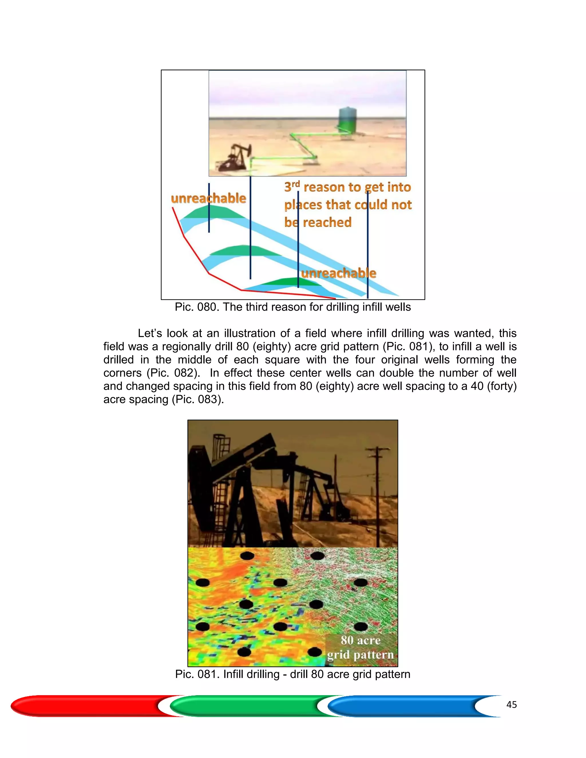
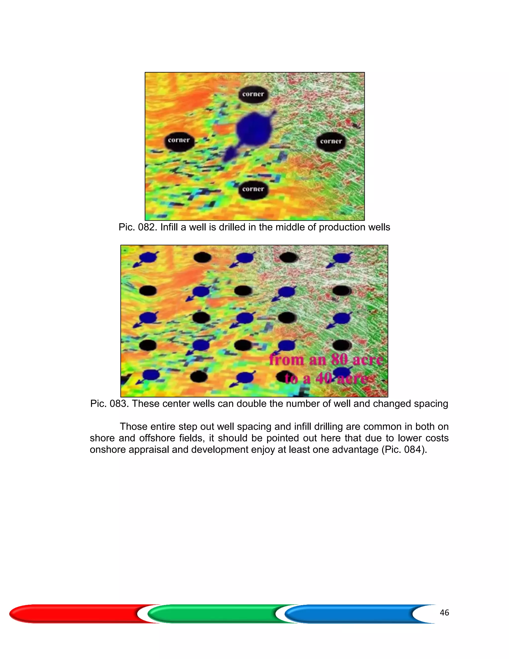
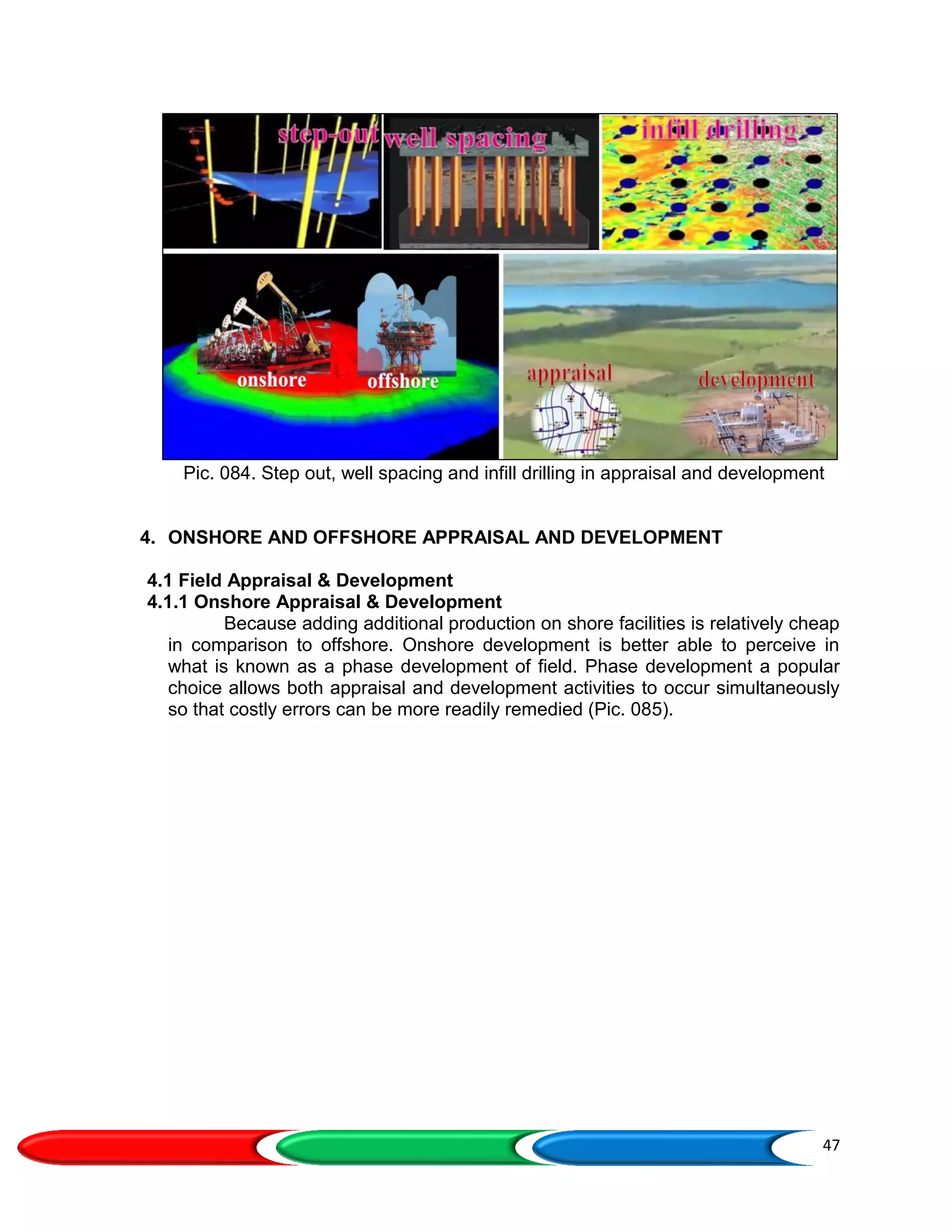
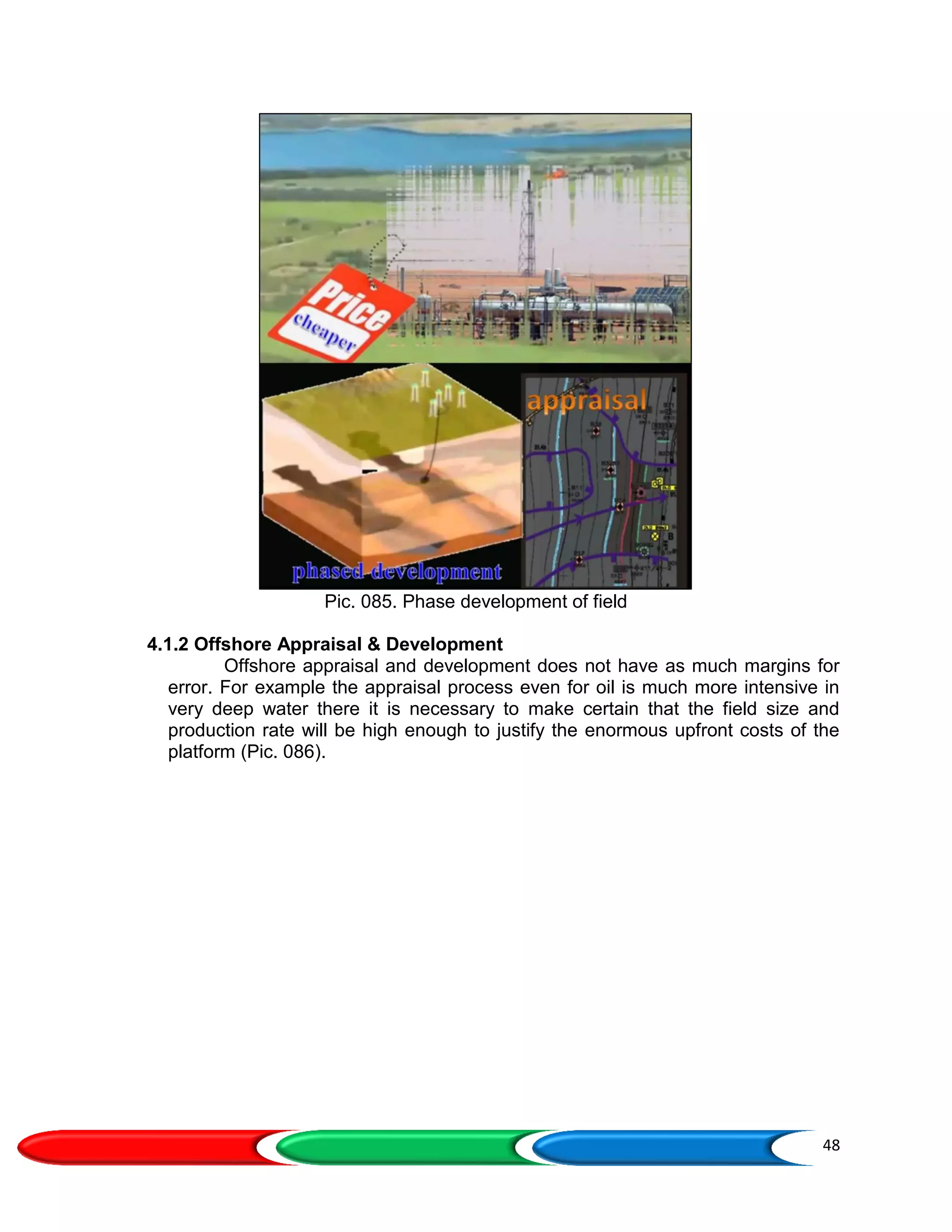
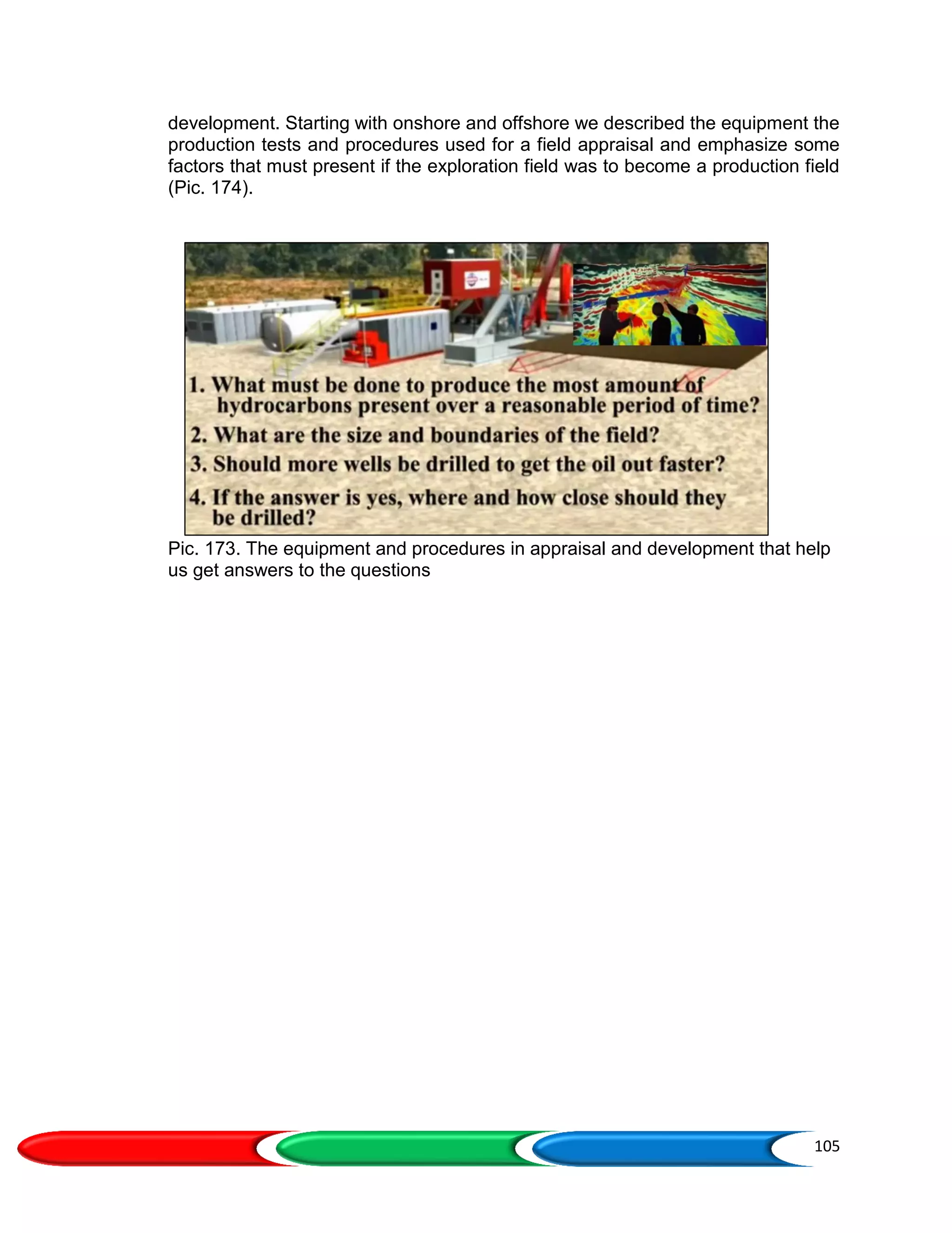
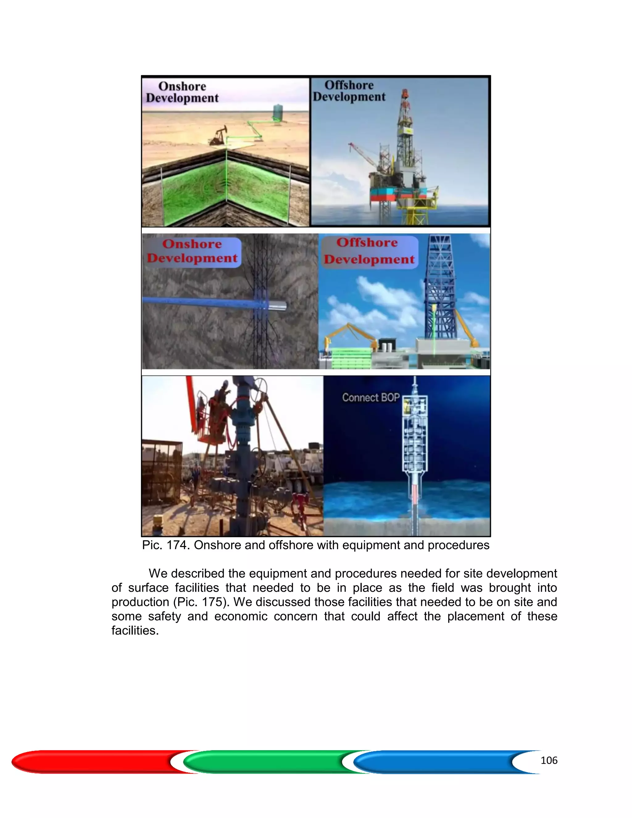
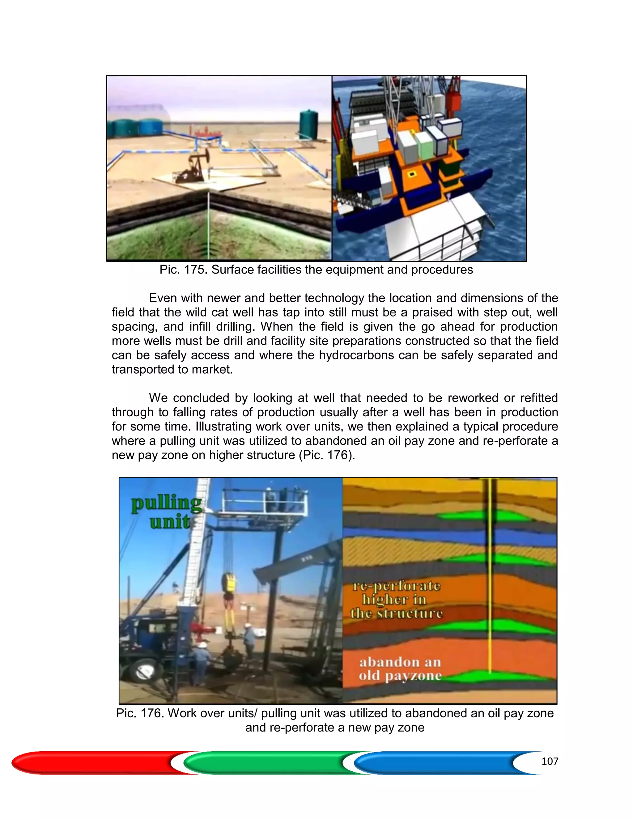
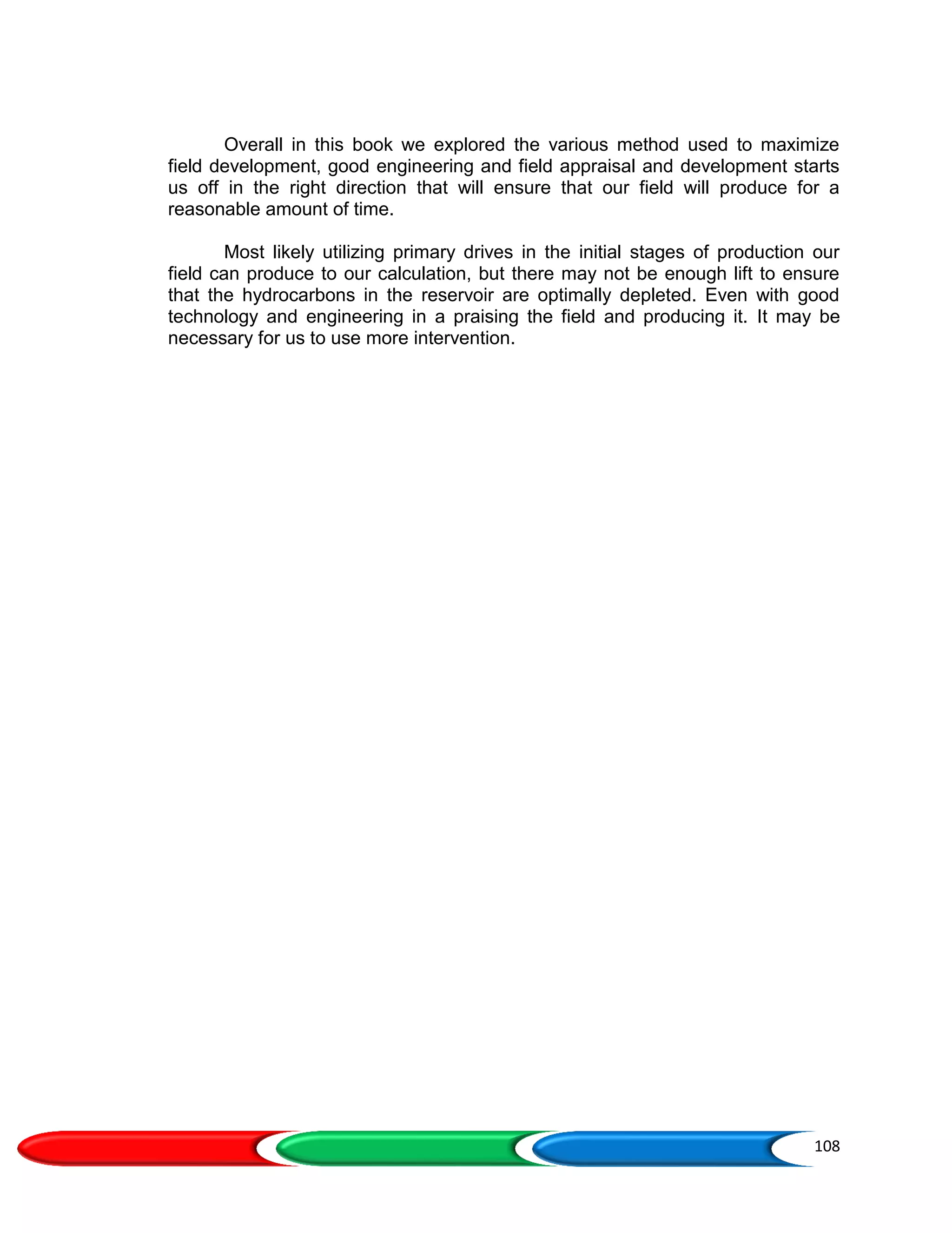
PETROLEUM
APPRAISAL & DEVELOPMENT
OVERVIEW
i
FOREWORD
This book, with named PETROLEUM APPRAISAL AND DEVELOPMENT
OVERVIEW is an overview of petroleum appraisal and development describes
hydrocarbon production, rate of production, the equipment & procedures in field
appraisal and development, the equipment & procedures site development, well work
over units. The exploration and production wells describes exploration well evolves into
production wells, exploration & production team, appraisal phase of field development,
value of information, information testing & logs, DST, WFT & IP test, and onshore &
offshore rigs.
Field appraisal and development procedures describe the spill point of the
structure (Anticline traps), the delineation wells, parameters affecting quality of the
reservoir, appraising & developing Stratigraphic traps, OOIP, OGIP and oil production
rate, Step-out drilling, well spacing, the infill wells. The onshore & offshore appraisal and
development describes field development scenario phase, the equipment & procedures
in developing offshore field, two major safety issues in offshore, offshore platform
surface facilities, production site preparations (onshore & offshore), onshore site
preparations (production site preparations process, remote ensure location, the gas
fields), offshore site preparation (types of construction on offshore, deeper unprotected
water surface facilities, Concrete gravity platforms, The tension leg platform, The FPSO
Vessels.
This book also describe generally about Improving hydrocarbon production,
consist of easy & hard production, production problems, reconditioned or repaired for
optimal production, work over rig types, types of work overs, the work overs process
onshore, re-stimulation, repairing casing leaks, and finally repairing faulty well
equipment.
Suggestions and constructive criticism are expected in the preparation of the
next book about Overview petroleum industry and Overview Mining Industry.
October, 2018
A. ANRIANSYAH
ii
TABLE OF CONTENTS
FOREWORD............................................................................................................................... ¡
TABLE OF CONTENTS.............................................................................................................. ¡¡
1. INTRODUCTION.......................................................................................................................1
1.1 Hydrocarbon Production....................................................................................................1
1.2 Rate of Production.............................................................................................................2
1.3 The Equipment & Procedures in Field Appraisal and Development..................................4
1.4 The Equipment & Procedures Site Development..............................................................6
1.5 Well Work over Units.........................................................................................................8
2. EXPLORATION AND PRODUCTION WELLS.......................................................................10
2.1 Exploration Well Evolves Into a Production Wells...........................................................10
2.2 Exploration & Production Team.......................................................................................11
2.3 Appraisal Phase of Field Development............................................................................13
2.4 Value of Information (VOI)...............................................................................................14
2.5 Information Testing & Logs..............................................................................................15
2.5.1 DST, WFT & IP Test...............................................................................................17
2.6 Onshore & Offshore Rigs.................................................................................................23
3. FIELD APPRAISAL AND DEVELOPMENT PROCEDURES.................................................24
3.1 The Spill Point of the structure (Anticline traps) …..........................................................25
3.2 The Delineation Wells......................................................................................................27
3.3 Parameters Affecting the Quality of the Reservoir...........................................................29
3.4 Appraising & Developing Stratigraphic Traps..................................................................29
3.5 OOIP, OGIP and Oil Production Rate..............................................................................32
3.6 Step-out Drilling...............................................................................................................33
3.7 Well Spacing....................................................................................................................34
3.7.1 Field Development Earlier Times............................................................................35
3.7.2 Heavy Oil Fields & Gas Field’s Area Spacing.........................................................39
3.8 The Infill Wells.................................................................................................................41
3.8.1 The Reasons for Drilling Infill Wells........................................................................42
4. ONSHORE AND OFFSHORE APPRAISAL AND DEVELOPMENT......................................47
4.1 Field Appraisal & Development.......................................................................................47
4.1.1 Onshore Appraisal & Development........................................................................47
4.1.2 Offshore Appraisal & Development........................................................................48
4.2 Onshore & Offshore Development Cost..........................................................................49
4.3 Field Development Scenario Phase................................................................................51
4.4 The Equipment & Procedures In Developing Offshore Field….......................................52
4.5 Two Major Safety Issues in Offshore…...........................................................................59
4.6 Offshore Platform Surface Facilities................................................................................64
4.7 Production Site Preparations (Onshore & Offshore)........................................................65
4.8 Onshore Site Preparations..............................................................................................66
4.8.1 Production Site Preparations Process....................................................................67
4.8.2 Remote Ensure Locations......................................................................................69
4.8.3 The Gas Fields.......................................................................................................69
4.9 Offshore Site Preparation................................................................................................70
4.9.1 Types of Construction On Offshore........................................................................71
4.9.2 Deeper Unprotected Water Surface Facilities........................................................74
4.9.3 Concrete Gravity Platforms.....................................................................................75
iii
4.9.4 The Tension Leg Platform......................................................................................77
4.9.5 The FPSO Vessels.................................................................................................78
4.9.6 Subsea Production Systems...................................................................................80
5. IMPROVING HYDROCARBON PRODUCTION ...................................................................81
5.1 Easy & Hard Production..................................................................................................81
5.2 Production Problems.......................................................................................................83
5.3 Reconditioned or Repaired For Optimal Production........................................................85
5.4 Work over Rig Types.......................................................................................................86
5.4.1 The Slick Line Wireline Units..................................................................................87
5.4.2 Electrical Conducting Wireline Units.......................................................................89
5.4.3 Coiled- Tubing Units...............................................................................................90
5.4.4 The Pulling Units.....................................................................................................92
5.5 Types of Work Overs.......................................................................................................94
5.6 The Work Overs Process Onshore..................................................................................95
5.7 Re-Stimulation.................................................................................................................98
5.8 Deepening.......................................................................................................................99
5.9 Repairing Casing leaks…………...................................................................................101
5.10 Repairing Faulty Well Equipment................................................................................102
6. CONCLUSION .....................................................................................................................104
REFERENCES..........................................................................................................................109
1
1. INTRODUCTION
After completed wildcat drilling we're ready to put the well on production,
but first we need to appraise the field before we start any development. We need
to ask the questions like how much oil is in place in this area? How big are the
boundaries? How many wells are we going to drill? What is the spacing between
the wells? Are they going to be close together or far apart? These are the
questions that we need to answer, so that we can maximize our recovery over a
reasonable mount of time.
1.1 Hydrocarbon production
As we know in Reservoir performance present day technology, does not
allow us to produce 100% (one hundred percent) of the hydrocarbons found in
any given reservoir (Pic. 001). For example lighter hydrocarbons with more
hydrogen molecules have higher production rates than heavier ones with more
carbon molecules (Pic. 002).
Pic. 001. HC production is not 100%
2
Pic. 002. Lighter HC with more hydrogen molecules have higher production rates
1.2 Rate of production
Beside the hydrocarbon properties, other factors affecting the rate of
production might include the types of primary drives found in the reservoir or
secondary drives introduced into the rise of that are used to force the oil to the
surface (Pic. 003).
Pic. 003. Secondary drive to force the Oil to surface
In other words the final percentage of hydrocarbons retrieval from a
particular well and reservoirs not only depends on the type and quantity of the
reservoirs hydrocarbon (Pic. 004), but also on other factors like viscosity,
porosity, permeability and pressure encountered (Pic. 005). That said no that
3
final percentages of overall production can be greatly increased by good
engineering that includes good planning (Pic. 006).
Pic. 004. Quantity and Type of Oil and gas
Pic. 005. Others factor in Oil and gas production
4
Pic. 006. Good engineering and planning in oil and gas production
Suffice to say that the opposite is also true, there for causing for a brief
period to run a few more tests in what is known as best practices in field
appraisal the overall productivity on the well and the field can be maximized (Pic.
007).
Pic. 007. Best practices in field appraisal
1.3 The Equipment & Procedures in Field Appraisal and Development
In this book we will explain in an illustrates the equipment and procedures
involved in field appraisal and development that will help but we get answers to
the questions just raised at the start of this book (Pic. 008).
5
Pic. 008. The equipment & procedures in field appraisal and development
We’re needed we’ll highlight the similarities and differences between
onshore and offshore field development (Pic. 009). Starting with onshore we’ll
described the equipment, the production tests and procedure used for a field
appraisal and emphasized some factors that must be present if the exploration
field is to become a production field (Pic. 010).
Pic. 009. Onshore and offshore field development
6
Pic. 010. Onshore equipment, production tests and procedure
1.4 The Equipment & Procedures Site Development
Next will described the equipment and procedures needed for site
development of surface facilities that need to be in place as the fields brought
into production (Pic. 011). We’ll discussed this facilities need to be on site and
some safety and economic concerns that might affect the placement of these
facilities (Pic. 012). In discussing offshore field appraisals, development and site
preparations factors such as the depth of the water and the intensity of the wind
and waves exclusive to offshore field development will be addressed (Pic. 013).
7
Pic. 011. Oil Operations flow chart
Pic. 012. Surface facilities on site with safety & economic concern
8
Pic. 013. Offshore field appraisals, development and site preparations
1.5 Well Work Over Units
We’ll conclude by looking at well work over units that are designed for
wells that need to be re worked or refitted due to falling rates of production (Pic.
014), illustrating work over units we’ll then explain how these units are used for
various conditions (Pic. 015).
9
Pic. 014. Work over units due to falling rates of production
Pic. 015. Offshore work over units
10
Over all in this book we’ll explore the various methods used to maximize
field development during the time that the field is being appraised and then
produced (Pic. 016).
Pic. 016. Various methods used to maximize field development
2. EXPLORATION AND PRODUCTION WELLS
2.1 Exploration Well Evolves Into A Production Wells
Before getting into details of the equipment and procedures involved and
field appraisal and development, lets we walk through a quick outline of how an
exploration well evolves into a production wells (Pic. 017). During this transition
phase the exploration teams first step is to conduct an initial potential test or IP
test before a preliminary field appraisals can be prepared, it is the data obtain
from this test that will help guide to development for this field appraisal and will
include a plan for step out drilling and well spacing (Pic. 018).
11
Pic. 017. An exploration well evolves into a production wells
Pic. 018. IP test, step out drilling and well spacing
2.2 Exploration & Production Team
Once the field exploration and wild cat has made us go forward, however
this exploration well will become a production well at this point the first thing that
needs to be changed is usually the expertise required by the well site
engineering team as we might imagine the skill needed for successful exploration
differ from skill needed for successful production and field development (Pic.
019).
12
Pic. 019. Well site engineering in exploration, production team and development
For example exploration engineers or expert in selecting where to drill a
wild cat well with only incomplete information about the sub surface (Pic. 020).
Production engineers on the other hand have access to much more information
and data that was collected by the exploration team (Pic. 021).
Pic. 020. Exploration team selecting where to drill a wild cat well
13
Pic. 021. Production engineers have access data
2.3 Appraisal Phase Of Field Development
The Appraisal Goal is improving the quality of the data and reducing
uncertainty and the outcome are well fluid characteristics, OOIP, Recoverable oil,
production profile, with sufficient uncertainty. The Appraisal Method are more
appraisal wells will be drilled and more measurements. The Subsurface Team
provide robust model of a reservoir from seismic data, appraisal wells and well
logs and well tests. The Appraisal tools are multiple simulation with varying well
count and location and type, tuning PDF for stochastic parameters (Pic. 022).
14
Pic. 022. Reservoir Model Tuning PDF ‐ CDF Production & Pressure
There are several methods and strategies to reduce uncertainty. There is
a trade off between capital cost and uncertainty. The Methods are DST (Drill
stem test), more appraisal wells, extended well test, early production, Staged
development. The Application Depends on Reservoir size and Characteristics,
Operator Strategy, and Available Technology (Pic. 023).
Pic. 023. Cost and risk graph
2.4 Value of Information (VOI)
The information can reduce uncertainty about future outcomes, decision
can be made that have better chances for a good outcome. However, such
15
information gathering is often costly. The VOI can be described as the amount a
decision maker should be willing to pay for a piece of information (Pic. 024)
Pic. 024. Schematic diagram of VOI decision tree
Development planning can based on a multi attribute decision model
where other technical factors A sto-chastic analysis for the multi attribute
decision model is performed to have a complete view of the possible outcomes
since the factors in the multi attribute decision model are measured qualitatively
and their values can vary depending on experts’ knowledge and experience.
2.5 Information Testing & Logs
This data along with other information with the most certainly include
drilling logs, coring results its data from the productivity tests and the wire line
information testing and logs (Pic. 025). The most difficult aspect of the job of the
production team will play to successfully and accurately interpret this data to
maximize oil and gas recovery (Pic. 026).
16
Pic. 025. Drilling logs, coring, the productivity tests and the wire line logs
Pic. 026. The production team to maximize recovery
Let we point out here that unlike wildcat exploration wells, development
wells are almost be successful because the reservoir has already been located it
just have to be defined (Pic. 027).
17
Pic. 027. Wildcat exploration & development wells
2.5.1 DST, WFT & IP Test
As we know in Formation evaluation, the last of three production tests
performed in a completed but still terms exploration well is the initial potential IP
test. The last of three productivity tests the IP test is run after DST (drill stem
test) and WFT (wire line formation testing) along with other indicators have
shown positive side of potential commercial quantities of hydrocarbons in the well
(Pic. 028). Because the purpose of the IP test is to better understand the wells
actual production rate, real time production conditions are created (Pic. 029).
Pic. 028. The IP test is run after DST and WFT
18
Pic. 029. The purpose of the IP test
These are valuations will help guide the final decisions in the field
appraisal, performed after the well has been put into production for at least a few
days to allow treating fluids to be retrieved and cleaned up, the IP (initial
potential) test is run over a period of about 24 (twenty four) hours. In that time the
actual number of barrels of oil and water also the cubic feet of gas that is
produced is carefully measured, in addition surface tubing pressure is recorded
(Pic. 030).
Pic. 030. The IP test is run over a period time
The data retrieve from this final productivity test then it allows the
exploration drilling team to better judge the potential of the well. If the decision is
made to proceed based on both engineering and economics input, then this well
and it's field will be mark for further appraisal and then developed (Pic. 031).
19
Pic. 031. Further appraisal and development
Before we continue let we discuss some of the challenges face when
we're running IP test, even experienced engineers when looking at IP data can
be misled. For example, completion in some types of reservoir comes in at a high
rate initially, but then decline rapidly over the next few weeks thus rendering the
reservoir uneconomic (Pic. 032).
Pic. 032. The reservoir uneconomic from IP data
It is there for recommended that a wild cat well be produced over a period
of time before committing to an ambitious drilling program (Pic. 033). In addition
gas reservoirs have their own special challenges when conducting IP tests,
because of the natural volatility of gas when attempting to container transported,
this gas is usually allowed to event directly into the atmosphere during an IP test
(Pic. 034). Unlike oil which can more safely be collected into tanks. due to
environmental concerns there for the amount of time that this gases allowed
event into the atmosphere is usually shorten. Because of the shorten period of
time that data collected during the IP test on a gas exploration well can
sometimes result in less accurate assessments (Pic. 035).
20
Pic. 033. Wild cat well drilling program
Pic. 034. The natural volatility of gas transported usually directly into the
atmosphere during an IP test
21
Pic. 035. The IP test of gas exploration well less sometimes accurate
Another problem with gas fields again lies in the properties of this highly
flammable gas and its unique requirements for retrieval and transportation. For
example, if gas discoveries are made some distance from a pipeline a number of
wells have to be drill before adequate gas reserves can be established to justify
link a pipeline into this field. For these reasons predictions for the future gas
production made depend and more testing this coupled with the need for more
complex equipment to both produce and transport this gas can result in delays
and the projects development and more upfront cost (Pic. 036).
22
Pic. 036. Gas discoveries distance from a pipeline
After the IP test for either onshore or offshore wild cat wells (Pic. 037), the
exploration team is going to define the outer perimeter of the pay zone (Pic. 038).
Pic. 037. The IP test for either onshore or offshore wild cat wells
23
Pic. 038. Define the outer perimeter of the pay zone
2.6 Onshore & Offshore Rigs
In most cases equipment used to drill the wild cat well will be used in the
initial stages of field appraisal, this means that Jack knife rigs and remote rigs will
continue to be used in land operations while barges, tenders, jack cups drill ships
etc. will be used offshore (Pic. 039). For a full description of these rig types we
can see in the petroleum drilling, for subsequent stages of filed appraisal and
development additional equipment will be brought on site to enable production
(Pic. 040).
Pic. 039. Onshore and offshore rigs
24
Pic. 040. Filed appraisal and development for production
3. FIELD APPRAISAL AND DEVELOPMENT PROCEDURES
Let’s look at the most common procedures involved and field appraisal
and development they are step-out drilling, well spacing and if necessary infill
drilling are all common procedures involved in appraisal and field development
(Pic. 041). Step-out drilling is done after a successful IP test, it helps identify the
size and shape of the field for calculating its future economic value (Pic. 042).
Pic. 041. step-out drilling, well spacing and infill drilling
25
Pic. 042. Step-out drilling after IP test
3.1 The Spill Point of the Structure (Anticline traps)
With a structural anticline trap the team of engineers begins by analyzing
seismic map by acquired previously during exploration to determine the spill point
of the structure. If we remember from Petroleum exploration about structural oil
traps, the spill point is the lowest point in the amount of anticline trap that
contains hydrocarbons (Pic. 043).
Pic. 043. The spill point of anticline trap
Think of a glass of water that once filled to the brim, the water is spillover if
we add more (Pic. 044). Like the liquid in the glass once the crown of the
anticlines structural trap has been filled to its spill point further accumulation of
hydrocarbons cannot occur due to lack of space in the trap (Pic. 045). These
hydrocarbons will then either leak out to the surface or be captured by another
trap as they migrate towards the surface (Pic. 046).
26
Pic. 044. The water is spillover
Pic. 045. Lack of space in the trap
Pic. 046. Captured by another trap
27
3.2 The Delineation Wells
The wells drilled to find the spill point are called delineation wells, these
delineation wells are drilled around the wild cat well in order to find the spill point
which will be indicated by what is known as the OWC (oil waters contact) line
(Pic. 047), as we know if the reservoir is full of oil then the OWC will be at on the
spill point (Pic. 048). On the other hand if only water is encountered this indicates
that there is no OWC (Oil water contact) line and that this delineation well is
outside of the boundaries of the pay zone, it will be invented as dry hole (Pic.
049).
Pic. 047. Delineation wells are drilled around the wild cat well
Pic. 048. The OWC will be at on the spill point
28
Pic. 049. If no OWC invented as dry hole
When OWC is not found the team will continue to drill until they find it, in
this case another delineation well will be drill closer to the wild cat well, additional
wells all called delineation wells are then drilled and circular in the wild cat well to
establish the parameters of the pay zone as defined by OWC (Pic. 050).
Pic. 050. Delineation wells- the pay zone as defined by OWC
29
3.3 Parameters Affecting the Quality of the Reservoir
Let we point out here that many delineation wells in onshore drilling will
most likely go on to be producing well, this may not be the case for offshore
delineation wells newer technology and offshore development is greatly changing
how offshore fields are develop, like most aspects of petroleum engineering
involved onshore and offshore drilling caution needs to be exerted when
evaluating data from step up drilling because the porosity, permeability, thickness
and pressure can change or disappeared at any point that's affecting the quality
of the reservoir (Pic. 051).
Pic. 051. Parameters affecting the quality of the reservoir
3.4 Appraising & Developing Stratigraphic traps
In appraising and developing stratigraphic traps the step up procedure is
different because the seismic data is of little value in these kinds of traps other
available less accurate data is used to help established this spill point (Pic. 052).
30
Pic. 052. Appraising and developing stratigraphic traps
Unlike pinpointing this field point in an anticline trap finding the spill point
in a stratigraphic trap unfortunately is less accurate resulting in a greater
potential for drilling dry delineation wells (Pic. 053).
Pic. 053. Stratigraphic trap - dry delineation wells
When looking for the spill point in a stratigraphic trap, it may be necessary
to rely on data from outline like producing fields in the vicinity were data is
31
available (Pic. 054). For instance if stratigraphic traps nearby have shown the
southeast northwest orientation, then the exploration team may uses a similar
pattern in their own gradual step out (Pic. 055).
Pic. 054. Available data in a stratigraphic trap
Pic. 055. Example gradual step out Stratigraphic traps
32
3.5 OOIP, OGIP and Oil Production Rate
In any event once the exact dimensions of the reservoir with it's thickness
and location of the hydrocarbon deposits have been determine from an accurate
mapping of the OWC point and then OOIP (original oil in place) can be calculated
for this sub surface structure (Pic. 056). As we know in Petroleum Reservoir
performance being able to calculate OOIP is important because it allows the
team to define and then determine the size and scope of future economic field
development (Pic. 057).
Pic. 056. OOIP (original oil in place)
Pic. 057. OOIP for future economic field development
33
Original Gas in Place (OOIP) & Original Gas in Place (OGIP) Volumetric
Method, formulated as follow:
Where:
A: Areal Extent (Seismic, drilling, reservoir modeling)
h: Net pay (Seismic, drilling, reservoir modeling)
ɸɵ: Porosity (well log, core sampling)
OS: Oil Saturation (well test)
FVFo: Oil Formation Volume Factor
These parameters are stochastic time varying parameters.
Oil Production Rate
Q=7.08 × K × h × (Pe‐ Pw) / Mu x B x ln(Re‐ Rw)
Q: Oil Flow Rate (bopd)
h: Net pay (Seismic, drilling, reservoir modeling)
K: oil effective permeability
Pe: Formation Pressure
Pw: Well bore pressure
Mu: Viscosity
B: Formation Volume Factor
Re: Drainage radius
Rw: Well bore pressure
There are 3 (three) Well test and curve fitting (simple models) such
Exponential, Harmonic, Hyperbolic. And sophisticated models there are
Reservoir model, and energy balance methods.
3.6 Step-out Drilling
Step-out drilling therefore whether in structural traps like anticline or
stratigraphic traps like a pinch out is important when conducting a field appraisal
for future development (Pic. 058).
34
Pic. 058. Step-out drilling in appraisal & development
3.7 Well Spacing
Once the shape, size, and thickness of the contours of the field have been
defined utilizing step-out drilling, the next major issue to address is well spacing
(Pic. 059). Well spacing involves a plan program that determines the optimal
number and spacing of wells that need to be drilled to deplete a given reservoir
over a reasonable period of time (Pic. 060). In fact it makes better economic
sense to produce the oil at a faster rate with additional wells if those wells can
produce more than the cost to drill them how many wells those are too many?.
Pic. 059. Well spacing after step-out drilling
35
Pic. 060. Well spacing - optimal number and spacing of wells over period of time
3.7.1 Field Development Earlier Times
As we remember old pictures from earlier times when derrick dominated
the landscape over an oil field (Pic. 061), build practically on top of each other
these wells were drilled so closely together that they quickly exhausted the
hydrocarbons natural lift out of the formation (Pic. 062). The result was that in
these oil wells production became so low, they had to be abandoned even
though oil still trapped in the formation these wells did not have enough lift for the
oil to flow to the surface (Pic. 063).
Pic. 061. Derricks in the landscape over an oil field
36
Pic. 062. Drilled closely made quickly exhausted the HC natural lift
Pic. 063. Oil still trapped in the formation - not enough lift to flow to the surface
Good engineering and a better understanding of the reservoir over the
years fortunately have greatly increased our ability to improve the percentages of
the amount of hydrocarbons that can be produced from a given reservoir (Pic.
064), well spacing therefore is a strategy that helps improve these percentages
of hydrocarbon production while recognizing economic reality (Pic. 065).
37
Pic. 064. Good engineering and knowledge of the reservoir improve production.
Pic. 065. Well spacing helps improve production
To arrive an optimal number, assumptions about the future costs of
equipment and personnel, the spot and future prices of oil and gas and interest
rate, have to be made (Pic. 066). In addition fluid viscosity should also be added
to the equation (Pic. 067).
38
Pic. 066. Assumptions the future costs of equipment and personnel, the spot and
future prices of oil and gas and interest rate.
Pic. 067. Fluid viscosity
For most development wells oil well spacing are typically 40 (forty), 80
(eighty) or 160 (one hundred and sixty) acres of part, remember that there are
247 (two hundred and forty seven) acres in a kilometers squared (Pic. 068), there
can be exceptions to how far apart producing wells need to be.
39
Pic. 068. Development wells of well spacing example
3.7.2 Heavy Oil Fields & Gas Fields Area Spacing
The heavy oil fields for example could be drilled as tightly as ½ (one half)
acre per well, gas fields on the other hand typically use a 640 (six hundred and
forty) acres spacing (Pic. 069).
Pic. 069. Heavy oil fields & gas fields area spacing
40
In any events well spacing that defines the number and location of wells to
be drilled along with step out drilling are essential component in field
development. By knowing the location and the number of wells we will be drilling
we can plan for the costs of the overall equipment like surface facilities,
personnel, pipelines general oilfield equipment etc. (Pic. 070).
Pic. 070. Surface facilities, personnel, pipelines general oilfield equipment etc.
Being able to put a tentative price tag on estimated costs of development
and production we are now better able to answer the question of whether we
have enough produce able hydrocarbons in our field to justify all the up front and
subsequent costs (Pic. 071). After the step-out drilled field has been evaluated
optimally spaced wells have been plan and the decision to go forward has been
made based on the field appraisal the process of drilling production wells to
produce hydrocarbons begins (Pic. 072). Like all plans, falling production rates in
a reservoir over time they forced field development plans to be revisited.
Pic. 071. Price tag on estimated costs to answer the question
41
Pic. 072. Production wells
3.8 The Infill Wells
These wells are known as infill wells (Pic. 073). unlike step-out drilling and
well spacing infill drilling usually is done after the well has been in production for
some time so the equipment conduct infill drilling will be that have a production
well not and exploration well (Pic. 074).
Pic. 073. The infill wells
42
Pic. 074. Well spacing infill drilling after the well has been in production
3.8.1 The Reasons for Drilling Infill Wells
There may be several reasons for drilling infill wells, here we will
described three; (1) the first reason to drill infill wells is due to a re-evaluation in
the time needed to deplete reservoir (Pic. 075), remember oil fields (reservoir
models and properties) are not always homogenous for example some section of
the reservoir may prove to be of lower porosity or permeability that was
calculated an original appraisal, these changes could adversely delayed the
times that this field could have been adequately depleted using the original
spacing (Pic. 076).
Pic. 075. First reason to drill infill wells
43
Pic. 076. Well spacing - reservoir models and properties not homogenous
When non homogeneous conditions arise these newly drilled infill well with
usually encounter a reservoir pressure close to the original values allowing
production to proceed as planned (Pic. 077).
Pic. 077. Infill wells in non-homogeneous
(2) The second reason for infill drilling is that once primary of recovery has
been depleted, secondary and tertiary recovery method may have to be initiated
in the field. A secondary and tertiary recovery method as we know in Reservoir
Performance can require up to 50% (fifty percent) more holes and drill during
primary recovery (Pic. 078). In these cases additional wells called injector wells
are drilled to add fluid under pressure into the formation. Even though injector
wells can either previously drill producing wells or newly drilled ones, these
injector wells can greatly increase the number and reduce the spacing of drilled
wells in the field (Pic. 079).
44
Pic. 078. Secondary and tertiary recovery - up to 50% (fifty percent) more holes
Pic. 079. The injector wells can increase the number and reduce the spacing of
drilled wells
(3) The third reason for drilling infill wells is to get into places in the
reservoir that could not be reached by the original spacing and configuration of
the well (Pic. 080).
45
Pic. 080. The third reason for drilling infill wells
Let’s look at an illustration of a field where infill drilling was wanted, this
field was a regionally drill 80 (eighty) acre grid pattern (Pic. 081), to infill a well is
drilled in the middle of each square with the four original wells forming the
corners (Pic. 082). In effect these center wells can double the number of well
and changed spacing in this field from 80 (eighty) acre well spacing to a 40 (forty)
acre spacing (Pic. 083).
Pic. 081. Infill drilling - drill 80 acre grid pattern
46
Pic. 082. Infill a well is drilled in the middle of production wells
Pic. 083. These center wells can double the number of well and changed spacing
Those entire step out well spacing and infill drilling are common in both on
shore and offshore fields, it should be pointed out here that due to lower costs
onshore appraisal and development enjoy at least one advantage (Pic. 084).
47
Pic. 084. Step out, well spacing and infill drilling in appraisal and development
4. ONSHORE AND OFFSHORE APPRAISAL AND DEVELOPMENT
4.1 Field Appraisal & Development
4.1.1 Onshore Appraisal & Development
Because adding additional production on shore facilities is relatively cheap
in comparison to offshore. Onshore development is better able to perceive in
what is known as a phase development of field. Phase development a popular
choice allows both appraisal and development activities to occur simultaneously
so that costly errors can be more readily remedied (Pic. 085).
48
Pic. 085. Phase development of field
4.1.2 Offshore Appraisal & Development
Offshore appraisal and development does not have as much margins for
error. For example the appraisal process even for oil is much more intensive in
very deep water there it is necessary to make certain that the field size and
production rate will be high enough to justify the enormous upfront costs of the
platform (Pic. 086).
49
Pic. 086. Offshore appraisal and development - no error margins
4.2 Onshore & Offshore Development Cost
This is a very different economic profile than that for onshore or for
shallow water development where each well can stand alone and be profitable in
its own right. Offshore the field in deep water must be large enough to justify the
added costs to development (Pic. 087).
Pic. 087. Onshore and offshore - justify cost development
Once all the available data has been evaluated in a field appraisal, a final
decision will be made that determines the next step. If hydrocarbon are present
50
in the economic quantities and if they can cover the costs of the development
and if economic conditions are right the company will most likely developed the
field
Onshore many times the wild cat well as well as some of the delineation
wells drilled during step-out drilling can quickly and easily be ready for
production. In addition portable jack knife land rig can be pulled by trailers to the
site on newly constructed or existing roads to complete the drilling plan as
outlined in the appraisal (Pic. 088).
Pic. 088. step-out drilling portable jack knife in appraisal
As we might guess in very shallow protected offshore fields, development
made proceed similarly to those onshore. The deeper the water and increasingly
intensity of the wind and waves sitting on top of the field however present
additional challenges that usually increase costs and the time required to get the
field into production (Pic. 089).
51
Pic. 089. Shallow protected - deeper offshore fields
4.3 Field Development Scenario Phase
Commonly there are 7 (seven) Field Development Scenario phase. First
Depletion phase (Strategy may Natural Depletion, Natural Depletion followed by
Water/Gas Injection for Pressure Maintenance, or Natural Depletion followed by
Water flooding for Secondary Recovery). Second Production phase (Strategy
Different Production Profile for the same UR, Pre-drilling - Starting production at
plateau rate, Short plateau rate, Long plateau rate). Third Lifting phase (Strategy
may Natural flow at minimum wellhead flowing pressure, Artificial lifting flow,
Artificial lifting flow providing some extra surface blustering pressure).
The fourth Well Architecture phase (Strategy may Vertical, Deviated,
Horizontal, or Multilateral wells), the fifth Perforation phase (Strategy may Single
Flow Unit, Commingled Flow Units, or Partial Penetration), the sixth Completion
phase (Strategy may Single Completion onshore - Dry Completion offshore, or
Dual Completion onshore – Subsea Completion offshore), the last one seventh
Surface Facilities phase (Strategy may Crude to be sent to pre-existing onshore
Facilities, or Dedicated in-situ Facilities onshore or offshore).
52
4.4 The Equipment & Procedures In Developing Offshore Field
Let’s examine the equipment and procedures used to address these
challenges in developing a field offshore (Pic. 090). We’ll begin with the most
protected about offshore locations in shallow protected waters found in marshes
and estuaries near land production procedures are very similar to those found
onshore (Pic. 091).
Pic. 090. The equipment and procedures in developing a field offshore
Pic. 091. Marshes and estuaries procedures similar onshore
Here barge mounted rig are easily pushed to location where the barge is
then flooded until it sits on the bottom. Once the vertical well is drilled and
completed the barges is then rift loaded and moved to the next location leaving
the well head and Christmas tree sticking up out of the water (Pic. 092).
53
Pic. 092. Barge mounted rig and well head / Christmas tree
For very shallow water depths of less than 10ft (ten feet) dredgers are
used to cut access canals for the drilling barges. a work part is moved in a small
jacket or told tool has said down over the tree and pint to the bottom with piles
driven through its legs (Pic. 093).
Pic. 093. Dredgers for less than 10ft (ten feet)
This functions as a dock for small boats used by the operating personnel
and gives them it plays to stand while working on the tree, this jacket or towed
tool also protects the wellhead from being accidentally struck by other floating
barges boats or debris (Pic. 094). Barge mounted rigs are ideal for areas for
water depth is not exceed 25 ft (twenty five feet), not only can barges be used in
shallow water they can also be used onshore low line swampy areas (Pic. 095).
54
Pic. 094. A dock for small boats or towed tool
Pic. 095. Barge mounted rigs in shallow water
When water depths reach over 25 ft (twenty five feet), jack up rigs are
used to complete the drilling program. they able to drill straight holes not deviated
ones, these jack of usually follow a grid like patterns similar each of those used
onshore in protected waters each wells has a pile jacket that is either set down
over the tree after completion or can be preset in drill through from the
cantilevered floor of the jack up (Pic. 096).
55
Pic. 096. The jack up for over 25ft water
Wildcat and delineation wells drilled in deeper water with more intense
wind and wave action, using a jackup drillship or semi-submersible will be
cemented and abandoned once the appraisal is complete (Pic. 097). These holes
are considered expendable because the delay in building the platform and the
surface facilities to produce and support this field may take several years (Pic.
098).
Pic. 097. Jackup drillship or semi-submersible
56
Pic. 098. Building the platform and the surface facilities
Instead once a platform is deed necessary, it will be designed for the
precise water depth, the intensity of the wind and waves, and the bottom
condition. Constructed onshore and then brought to the site to be reconstructed
and install, the platform will have a drilling rig installed and the first thing that they
were drill is all new holes for production (Pic. 099).
Pic. 099. The offshore platform
57
As the water gets deeper, platform costs escalate sharply some vertical
wells with individual jackets or replaced by multiple directional wells they can be
drill from a single platform (Pic. 100). Largest fields however can still support
multiple platforms (Pic. 101).
Pic. 100. Multiple directional wells they can be drill from a single platform
Pic. 101. Multiple platforms in large field
A platform may have all the facilities associated with the rig or the rig
maybe tender supported (Pic. 102). If the platform is tender supported this
means that next to the platform there is a floating anchored bolt either ship-
shaped or semi-submersible (Pic. 103) .
58
Pic. 102. Offshore platform - tender supported
Pic. 103. Ship-shaped or Semi-submersible
On this platform anchor tender or the crew quarters, mud pits and pumps,
cement mixing, and pumping equipment, pipe and equipment storage, and other
necessary equipment’s lines connecting tender to the platform carry power,
cables, water, and mud (Pic. 104). After each well has drilled and completed on
and off platform there rig is skidded a few feet to the next slot and a new well is
drilled. When all the wells have been drilled the rig is lifted off the platform by
cranes on the tender and then the tender is towed to a new platform (Pic. 105).
59
Pic. 104. The platform anchor tender
Pic. 105. The tender is towed to a new platform after wells completed
4.5 Two Major Safety Issues in Offshore
Because crews can be in such close proximity to producing wells and
production facilities on platforms there are two major safety issues that on drill
offshore, unfortunately there are no easy answers to; (1) one should the
production wells be allowed to produce as they are drilled? or should all wells be
completed before production begin? (Pic. 106). (2) Two should the treating
facilities a major source a fire an explosion be placed on the same platform as
the living quarters of the crew or on another platform? (Pic. 107).
60
Pic. 106. One of two major safety issues that on drill offshore
61
Pic. 107. Treating facilities be placed on the same platform or not
As we might suspect the deeper the water the more economically
advantages it is to have the treating facilities, the producing wells, and the living
quarters all on one platform (Pic. 108). In the deepest water or very harsh
conditions a single platform is normally used either bottom supported or float with
attention like configuration.
62
Pic. 108. Offshore platform – bottom supported / floater with tension leg
Having separate platforms for the treating facilities the production wells
and the living quarters is just too prohibitive. Because of the risks to the people
and to the facilities in dealing with highly explosive flammable oil and gas,
offshore platform shouldn't here to the strict fire and safety codes (Pic. 109).
Pic. 109. Offshore platform and safety
The high costs and technology is needed to set platforms either floating or
bottom supported in extremely deep water has increased the uses of subsea
completions. Subsea completions are where the well head are installed on the
bottom of the ocean then connected by pipeline with nearby platforms (Pic. 110).
63
Pic. 110. Subsea completions
Here is an example in addition small fields can be developed in the vicinity
of older fields that may have surplus facility capacity (Pic. 111). Now that the
appraisal has been conducted and the wells drilled according to plan, it is now
time to start facility site preparation.
Pic. 111. Additional small fields surplus facility capacity
64
4.6 Offshore Platform Surface Facilities
In site preparation, surface facilities that allow the crew to perform their
jobs to support production on the well, these surface facilities include water and
gas separators, pipelines, pumping stations, water treatment plants etc. (Pic.
112).
Pic. 112. Offshore platform surface facilities
When at all possible it is best to house these facilities separately from the
crews living quarters, as explained earlier though sometimes this is impossible
due to prohibitive costs (Pic. 113).
Pic. 113. Production Facilities separately from the crews living quarters
65
4.7 Production Site Preparation (Onshore & Offshore)
Depending on the location of the reservoir, the steps to prepare the site for
production can vary, along with their financial cost (Pic. 114). site preparation for
easily accessible on shore locations where existing highways and pipelines can
be fairly straightforward, while site preparation for a remote deep water off shore
facilities is much more complicated (Pic. 115).
Pic. 114. The site preparation for production depend on location
66
Pic. 115. Site preparation onshore and offshore
4.8 Onshore Site Preparations
Most onshore site preparations for surface facilities to produce oil are very
simple and accessible locations near roads and modern day infrastructure (Pic.
116). As we know in drilling overview described the steps involved in preparing a
site so land drilling could be easily moved into place for exploration (Pic. 117), for
production the process is similar thus allow the production equipment and person
personnel to easily access the location (Pic. 118).
Pic. 116. Onshore production site preparations
67
Pic. 117. Exploration site preparation
Pic. 118. The production equipment and personnel
4.8.1 Production Site Preparations Process
The ground is leveled, a drainage system is installed, crushed rock, or
other surface stabilizing material is spread over the site (Pic. 119). In swamp
raised roads paved with planks may have to be constructed if they haven't been
already, but overall it is still a relatively inexpensive endeavor (Pic. 120).
68
Pic. 119. The ground, drainage, crushed rock, & spread stabilizing material
Pic. 120. Roads paved with planks
69
4.8.2 Remote Ensure Locations
In remote ensure locations far from a modern day infrastructure preparing
on site oil production facilities maybe more complicated and certainly more
expensive. Here not only access to the site must be built but also the means to
get the hydrocarbons truly refinery must be constructed. This made mean
building new roads and pipelines (Pic. 121).
Pic. 121. Remote locations site production facilities
4.8.3 The Gas Fields
As we mentioned earlier for example site preparations for developing gas
fields was not only be more precise that can also greatly increase the upfront
development costs (Pic. 122).
Pic. 122. Surface facilities gas fields
70
4.9 Offshore Site Preparation
Going offshore raises the site preparation costs concededly. In addition
the depth of the water and the intensity of the wind and waves also impact the
bottom line (Pic. 123). Preparing locations and shallow protected water such as
lakes or estuaries, although usually costing more than onshore or the simplest
(Pic. 124).
Pic. 123. Offshore site preparation
Pic. 124. Preparing locations and shallow protected water
71
4.9.1 Types of Construction On Offshore
Here we’ll explain three types of construction used offshore (Pic. 125). In
the first in shallow water dredged bottom material may be used to raise the
location above the water to create an island (Pic. 126). In the second wooden or
steel piles may be driven into the bottom to support wood or concrete deck and in
the third floating concrete barges are constructed towed to the site and then
floated to rest on the bottom (Pic. 127).
Pic. 125. Three types of construction on offshore
72
Pic. 126. Offshore site preparation - create an island
73
Pic. 127. Wooden or steel piles & floating concrete barges
On the island and the deck surface facilities are built on top after
construction is completed, when using the barge surface facilities or
prefabricated on it before the barge sent to the site (Pic. 128).
Pic. 128. Island, the deck, and barge surface facilities
74
4.9.2 Deeper Unprotected Water Surface Facilities
In deeper unprotected water surface facilities or constructed on bottom
supported steel platforms to provide the necessary load bearing space. Built and
installed in two sections these still platforms consist of a jacket extending from
the bottom of the ocean to justify the water line and the deck section (Pic. 129).
Pic. 129. In deeper unprotected water surface facilities
First the jacket is loaded on barge and towed to location. Second the
barges then partially flooded and the jacket is launched, next the structure is
floating horizontally at the surface by flooding selected jacket parts. Third the
jacket is brought slowly to a vertical position by floating different chambers, this
forces that jacket down to sit on the ocean floor, after that steel pipe is driven
through the jack kid legs deep into the sea bed (Pic. 130).
75
Pic. 130. Jacket site installation
In derrick barges then lifts the deck sections from a barge and set on the
jacket, finally the derrick barge stacks the prefabricated facility modules on the
deck (Pic. 131).
Pic. 131. Derrick barges lift the deck
4.9.3 Concrete Gravity Platforms
In isolated remote sites like the North Sea, concrete gravity platforms have
been build fabricated on land at remote construction sites these platforms are
floated to location and flooded to sink them to the bottom. Held in place largely
by their own weight, they may also have a few skirt piles distributed around their
piles for further stability (Pic. 132).
76
Pic. 132. Concrete gravity platforms
Although needed in deep unprotected waters to produce the fields there,
when the fields are depleted the steel and concrete platforms must eventually be
decommission and disposed of thus further increasing the costs (Pic. 133).
77
Pic. 133. Decommission and disposed of the steel and concrete platforms
4.9.4 The Tension Leg Platform
In very the deep water where steel or concrete platforms are cost
prohibitive buoyant platforms is increasingly being used. A popular configuration
of a buoyance platform is the tension leg platform which is tethered to pile pads
on the ocean for by strings of steel pipe (Pic. 134).
Pic. 134. The tension leg platform
The platforms movement and severe seizes is controlled by capping the
string under constant tension. In these buoyant platforms spars or buoyant
vertical cylinders are fixed to the bottom and stabilized by anchor lines. These
spars minimize vertical motion caused by surface conditions and thus able to
support production facilities in very deep water. In addition with today's precise
78
powerful computers that can't stabilize Movements Sea going vessels can be
temporary anchored in place and use instead of steel and concrete platforms
(Pic. 135).
Pic. 135. Buoyant platforms spars or buoyant vertical cylinders
4.9.5 The FPSO Vessels
The FPSO (floating production storage offloading) vessels can be either
ship-shaped or a semi-submersible used in conjunction with sub surface
completions they are cheaper than platforms because production does not have
to be delayed, while waiting for one of these mammoth platform to be built.
Likewise when the field is depleted these FPSO can easily be disconnected and
moved to another location (Pic. 136).
79
Pic. 136. The FPSO (floating production storage offloading) vessels
Floating production storage and offloading units (FPSOs) can operate in
water depths up to 3000m and are best suited for milder climates or where there
are limited pipeline systems to transport oil to shore. These ship-like vessels can
process all of the oil or gas produced from a reservoir, separating the oil and gas
and storing the oil until it can be offloaded to tankers for transportation (Pic. 137)
80
Pic. 137. Floating production storage and offloading units
The storage capacity of the FPSO allows oil to be stored and then
periodically offloaded to a tanker so that the tanker does not need to be on
standby for long periods while waiting to receive production. Subsea wells lift
production to the FPSO through risers. Most vessels use mooring systems
connected to a “turret”. The turret is mounted to the hull and allows the vessel to
rotate freely. Floating vessels as other floating structures are not suitable for
multiyear ice waters but could be a good solution for ice-free Arctic waters with
icebergs existing.
4.9.6 Subsea Production Systems
Subsea production systems are composed of wells, manifolds and
flowlines lying directly on the seafloor. Wells for semisubmersible platforms and
FPSOs are subsea wells drilled from the Mobile Offshore Drilling Unit.
Additionally subsea wells can be connected to other systems, like SPARS,
FPSOs or platforms to extend a reach to nearby reservoirs (Pic. 138).
81
Pic. 138. Subsea production systems
Oil and gas from subsea wells flow in flowlines to processing platforms or
to shore that may be in distance up to 160 km. The recent years’ tend is to
extract the oil and gas by subsea equipment only.
5. IMPROVING HYDROCARBON PRODUCTION
5.1 Easy & Hard Production
As we can see the economics and technology of preparing a site to
produce oil and or gas field depend in part on exactly where that oil or gas fields
is located, and as we may have heard the easy oil the oil is located onshore near
existing production infrastructure or shallow water offshore has already been
produced (Pic. 139). In the years to come oil gas production will come from
deeper more remote more hostile less accessible location, it will be with newer,
better technology that will help determine the economics and feasibility of getting
that oil and gas out of the ground and to market (Pic. 140).
82
Pic. 139. The easy oil located onshore shallow water offshore
Pic. 140. Oil & gas production from deeper, more remote, more hostile, less
accessible location
83
Once the oil and gas is in production there are still many tasks for the
teams of production and reservoir engineers to perform. With all of the variables
involved in producing oil and gas, it is a tribute to our modern day engineering
that we can do it so well (Pic. 141).
Pic. 141. The teams of production and reservoir engineers
5.2 Production Problems
Now let's look at some long term problems that can occur in production.
Pressures, temperatures, and water levels in the reservoir must be monitored
and controlled (Pic. 142). Corrosive substances like H2S gas CO2 gas and water
in the oil can destroy the steel pipe, eventually causing the equipment to fail (Pic.
143). In addition the production of scales for hard rock deposits that build up in
the inside of the pipes and valves and hydrates or slurry of frozen water and oil at
the surface can also cause problems by restricting the flow of the hydrocarbons
(Pic. 144).
84
Pic. 142. Monitor and control Pressures, temperatures, and water levels in the
reservoir
Pic. 143. Corrosive substances causing the equipment to fail
85
Pic. 144. The problems restricting the flow of the hydrocarbons
5.3 Reconditioned Or Repaired For Optimal Production
Over time therefore a producing oil or gas well will have to be
reconditioned or repaired if optimal production is to continue, known as the work
over and re completion a reconditioning or remedial the purpose of a work over is
to re-enter the well to repair it (Pic. 145).
Pic. 145. Reconditioned or repaired for optimal production
Smaller than the original drilling rig the work over can be brought to in on
shore site by trucks, to protected water site in mobile jacket barges, or to a
deeper water offshore location on a platform based unit mounted on skids (Pic.
146).
86
Pic. 146. The work over rigs
5.4 Work Over Rig Types
Work over units come in various types, here we will discuss (4) four work
over rig types. They are Slick-line units, Electrical conducting wireline units,
Coiled- tubing units, and The pulling units (Pic. 147).
87
Pic. 147. Types work over units
5.4.1 The Slick Line Wireline Units
The slick line wireline units these work over units consisted of a single
strand wire that is use for a routine main as of gas lift valves, chokes, sliding
sleeves and for cutting paraffin accumulation in the tubing (Pic. 148). Here is an
illustration of slick-line that is run during tubing under pressure using a lubricator,
this procedure is used to measure the tubing diameters to help better gauge
corrosion or deposits (Pic. 149).
88
Pic. 148. The slick line wireline units
89
Pic. 149. The slick line wireline process
5.4.2 Electrical Conducting Wireline Units
Electrical conducting wireline units as this illustration shows this multi
strand electrical conducting wire is used for logging perforating and setting plugs
and packers, it is run both over tubing under pressure and through casing when
the well is killed or taken off production (Pic. 150). This procedure is used to run
a production logs which can help determined fluid flow rates, engage the current
effectiveness of perforation (Pic. 151).
90
Pic. 150. Electrical conducting wireline units
Pic. 151. Run production logs - fluid flow rates
5.4.3 Coiled - Tubing Units
Coiled- tubing units as we can see here these units are small diameter
three a quarter inch to one and a half inch continuous tubing with no joints
spoiled off a real into the whole they can run either through to tubing or through
casing (Pic. 152). Coiled tubing unit can be used to clean out sand or to place
91
cement or removes scaly deposits they can also be especially used for working
horizontal holes (Pic. 153).
Pic. 152. Coiled- tubing units
92
Pic. 153. Coiled- tubing units uses
5.4.4 The Pulling Units
The pulling units these mobile on shore units using 2” (two inch) or 2 ½”
(two and a half inch) outside diameter jointed tubing, operate as a working the
pulling unit has multipurpose machines because they can be used for a routine
pulling of rods and tubing as well as for major work overs (Pic. 154). Notice that
the draw work here is smaller than those uses drilling rigs, rotary table in a
reverse circulating mud system can also be attached for drilling out plugs, junk,
or for deepening the hole (Pic. 155). These pulling unit work with the tree remove
so flowing wells have to be killed which means that production is stopped (Pic.
156).
Pic. 154. The pulling units
93
Pic. 155. The draw work, rotary table to drill out plugs, junk, or deepening the
hole
Pic. 156. Pulling unit work - production is stopped
The last one we mentioned here is not a work over rig, a conventional
drilling rig the drilling rig that was first used to drill the original holes on deep
water platforms, is left in place to later act as a work over rig (Pic. 157).
94
Pic. 157. Conventional drilling rig act as a work over rig
5.5 Types Of Work Overs
Using the right unit is important because there are many types of work
overs. let we discuss in a little more detail, the steps involved in doing a typical
work over using a pulling unit to reperforate a new zone above a depleted one
(Pic. 158).
Pic. 158. Pulling unit to re-perforate a new zone
As we know there may be more than one pay zone in the reservoir, often
the bottom zone is completed initially and produced to depletion. When this
occurs the well is then worked over to plugs off the old zone and completely new
one in the upper zone (Pic. 159).
95
Pic. 159. Worked over to plugs off the old zone and completely new one
5.6 The Work Overs Process Onshore
The process in an onshore well, (1) first load fluid is pumped down the
tubing to kill the well, (2) second when we get is moved location where the trees
removed and replaced with a BOP then the tubing and packers are pulled, (3)
third a packer called a cement retainer is run on an electric wireline and sets the
retainer above the old zone (Pic. 160). Next a tubing workstring and latch are run
into the retainer, followed by the pumping of cement down the tubing into the pay
zone until it pressures up and won’t take any more cement into the perforation
and this is called squeeze cementing (Pic. 161).
96
Pic. 160. The process/ procedure in an onshore well step 1st-3rd
Pic. 161. The process/ procedure in an onshore well step 4th
After that the tubing is unlatched from the retainer and a flapper in the
retainer swings closed to prevent cement from flowing back up, then water is
pump down the annulus and up the tubing and what is known as revert
circulation to clean out the cement left into the tubing (Pic. 162). After that the
tubing is pulled from the hole and a perforating gun on wireline sent down to
perforate the zone. finally the upper zone is fractured acidized or gravel packed
before the tubing and packers are run back down. The christmas tree is re
97
installed and the well is brought back to production (Pic. 163). To unload the kill
fluid, it might be necessary to pump liquid nitrogen down string coiled tubing run
inside the production tubing (Pic. 164).
Pic. 162. The process/ procedure in an onshore well step 5th
-6th
98
Pic. 163. The process/ procedure in an onshore well step 7th
-8th
Pic. 164. Pump liquid nitrogen down string coiled tubing
5.7 Re-Stimulation
The other types of work over might include re stimulation, here the original
pay zone may need to be re acidized or re-fractured (Pic. 165). And the example
of the Hydraulic fracturing operations (Pic. 166),
99
Pic. 165. Re-stimulation by re acidized or re-fractured
Pic. 166. Hydraulic fracturing operations
Hydraulic fracturing also known as “fracking” is an oil and gas extraction
method in which hydraulic pressure is used to create fractures in reservoir rock
and sometime in shale rock.
5.8 Deepening
Deepening to a new zone in this work over the existing perforations is
squeezed off and the hole is drilled deeper to a new zone. Because it is deeper a
casing liner has to be run, cemented, and completed (Pic. 167). As we can see
from our first example of a work over, it is favorable at much easier to deplete the
deepest zone first (Pic. 168).
100
Pic. 167. Deepening to a new zone
Pic. 168. Easier to deplete the deepest zone first
101
5.9 Repairing Casing Leaks
Repairing casing leaks, when casing leaks occur it may be necessary to
set a bridge plug below the leak and a packer tubing above the leak, cement is
then squeezed between the bridge and the packer to seal it like a patch (Pic.
169). Repairing casing leaks can also be fixed by setting scab liner over the
leaks. Scab liner is a short pieces smaller diameter casing with packers on both
ends or a pack with that extends outward to seal the leak (Pic. 170).
Pic. 169. Repairing casing leaks by set a bridge plug and a packer tubing and
cement like a patch
102
Pic. 170. Repairing casing leaks can also be fixed by setting scab liner over the
leaks
5.10 Repairing Faulty Well Equipment
Repairing faulty well equipment, here worn out down hole equipment is
replaced such as leaking tubing, broken sucker rods, malfunctioning gas lift
valves, or leaking packers (Pic. 171). As we can see maintenance operation is
vital in maximizing oilfield production, they required good engineering over the
life of the well and the field (Pic. 172).
103
Pic. 171. Repairing faulty well equipment
104
Pic. 172. Maintenance operation with good engineering
6. CONCLUSION
In this book we explained and illustrated the equipment and procedures
involved field appraisal and development that help us get answers to the
questions raised at the start of this book (Pic. 173). Where needed, we
highlighted the similarities and differences between onshore and offshore field
105
development. Starting with onshore and offshore we described the equipment the
production tests and procedures used for a field appraisal and emphasize some
factors that must present if the exploration field was to become a production field
(Pic. 174).
Pic. 173. The equipment and procedures in appraisal and development that help
us get answers to the questions
106
Pic. 174. Onshore and offshore with equipment and procedures
We described the equipment and procedures needed for site development
of surface facilities that needed to be in place as the field was brought into
production (Pic. 175). We discussed those facilities that needed to be on site and
some safety and economic concern that could affect the placement of these
facilities.
107
Pic. 175. Surface facilities the equipment and procedures
Even with newer and better technology the location and dimensions of the
field that the wild cat well has tap into still must be a praised with step out, well
spacing, and infill drilling. When the field is given the go ahead for production
more wells must be drill and facility site preparations constructed so that the field
can be safely access and where the hydrocarbons can be safely separated and
transported to market.
We concluded by looking at well that needed to be reworked or refitted
through to falling rates of production usually after a well has been in production
for some time. Illustrating work over units, we then explained a typical procedure
where a pulling unit was utilized to abandoned an oil pay zone and re-perforate a
new pay zone on higher structure (Pic. 176).
Pic. 176. Work over units/ pulling unit was utilized to abandoned an oil pay zone
and re-perforate a new pay zone
108
Overall in this book we explored the various method used to maximize
field development, good engineering and field appraisal and development starts
us off in the right direction that will ensure that our field will produce for a
reasonable amount of time.
Most likely utilizing primary drives in the initial stages of production our
field can produce to our calculation, but there may not be enough lift to ensure
that the hydrocarbons in the reservoir are optimally depleted. Even with good
technology and engineering in a praising the field and producing it. It may be
necessary for us to use more intervention.
109
REFERENCES
 Adams Michael, et. al, 2013, East Coast Oil and Gas Development Study, the
Ministry of Business, Innovation and Employment (MBIE).
 Etemaddar Mahmoud, 2016, Concept Selection for Deep Water Field
Development Planning, Field Development and Operations, Department of
Petroleum Engineering and Applied Geophysics, NTNU Trondheim.
 G. Gordon, 2017, The Appraisal of Oil/Gas Mineral Interests (Completed or
Producing) For Ad‐Valorem Tax Purposes In Texas, Tax Year MHO.
 Håvard Devold, 2013, "Oil and gas production handbook An introduction to oil
and gas production, transport, refining and petrochemical industry", ABB Oil and
Gas.
 Harvey Toni, 2014, GUIDANCE NOTES FOR ONSHORE OIL AND GAS FIELD
DEVELOPMENT PLANS, free handbook, Sr Geoscientist consultant.
 J. Efrain Rodriguez, Sanchez, J. Martin Godoy, Alcantar, I. Ramirez, Antonio,
2012, Concept Selection for Hydrocarbon Field Development Planning, Scientific
Research Publishing.
 Lau Richard, Overview of the Oil Industry – Appraisal and development, 2014.
 Moricca Giuseppe, 2017, Basic of Criteria, Strategy, and Process for a Proper
Arctic Offshore Field Development Plan, Slide share, Senior Petroleum Engineer
consultant.
 Moricca Giuseppe, 2017, Step-by-step Procedure for an effective Field
Development Plansupported by the related Basic Engineering Concepts, Slide
share, Senior Petroleum Engineer consultant.
 Moricca Giuseppe, 2018, How to improve the current poor Practices in Defining
Fields Development, Slide share, Senior Petroleum Engineer consultant.
 Pless Jacquelyn, 2012, Natural Gas Development and Hydraulic Fracturing: A
Policymaker’s Guide, National Conference of State Legislatures.
 Singh Virendra, Yemez Ivan, Izaguirre Elena, Racero Alvaro, 2017, Optimal
Subsurface Appraisal: A Key Link to the Success of Development Projects-Few
Examples, American Journal of Applied Sciences.
 Stoneburner Dick, 2013, The Exploration, Appraisal and Development of
Unconventional Reservoirs: A New Approach to Petroleum Geology, BHP Billiton
Petroleum, AAPG Distinguished Lecture.
 http://africaoilg*sreport.com/
 https://arabiangaze*te.com/
 https://auduboncomp*nies.com/
 https://www.b*ge.com/
 https://www.s*b.com/resources.aspx
 https://www.corel*b.com/
 http://iodp.org/
 http://petrolog.net/
 https://www.hrhgeol*gy.com/
 http://www.drillingc*ntractor.org/
 http://www.drillingf*rmulas.com/
 http://www.earthscienceworld.org/
 https://editors.eol.org/eoearth/wiki/Main_Page
110
 https://fossil*il.com/
 http://www.w*rkover-rigs.com/
 https://geog.ucsb.edu/
ABOUT THE WRITER
Having more than 10 years of work experiences in Oil and
Gas Industry both exploration and development such as
Bandarjaya / Lampung III Project (at PT. Harpindo Mitra
Kharisama), Reevaluation of Diski Oil field - North Sumatra
basin (at TAC PEP – PKDP), and Preliminary Fractured
evaluation some oil fields (at PT. OPAC Barata-Kejora Gas
Bumi Mandiri), Evaluation for Klamono Block - Salawati Basin
and Evaluation for Tebat Agung Block - South Sumatera Basin (at Trada Petroleum Pte.
Ltd.), Operation of Kampung Minyak oilfield (at KSO Pertamina EP – PKM) and
Formation Evaluation of Tsimororo Field - Madagascar (at Lemigas), J1J3 Oil Fields -
NW Java basin (at ECC).
He was graduated from Institute Technology of Bandung, Geology Engineering
Department in 2006 as S.T. (Sarjana Teknik) or Bachelor degree in Geology. Before that
He was graduated from SMUN 2 Cimahi (Senior High School) in 2001, and from SLTPN
9 Cimahi (Junior High School) in 1998, also graduated from SDN KIHAPIT I (Elementary
school) in 1995.
Surat Al-Fatihah
1. Dengan nama Allah Yang Maha Pengasih, Maha Penyayang.
2. Segala puji bagi Allah, Tuhan seluruh alam,
3. Yang Maha Pengasih, Maha Penyayang,
4. Pemilik hari pembalasan.
5. Hanya kepada Engkaulah kami menyembah dan hanya kepada Engkaulah kamimohon pertolongan.
6. Tunjukilah kami jalan yang lurus,
7. (yaitu) jalan orang-orang yang telah Engkau beri nikmat kepadanya; bukan (jalan) mereka yang dimurkai, dan bukan (pula jalan)
mereka yang sesat.
AL IKHLASH (MEMURNIKAN KEESAAN ALLAH)
Dengan menyebut nama Allah Yang Maha Pemurah lagi Maha Penyayang
1. Katakanlah: "Dia-lah Allah, Yang Maha Esa.
2. Allah adalah Tuhan yang bergantung kepada-Nya segala sesuatu.
3. Dia tiada beranak dan tidak pula diperanakkan,
4. dan tidak ada seorangpun yang setara dengan Dia
AL-FALAQ (WAKTU SUBUH)
Dengan menyebut nama Allah Yang Maha Pemurah lagi Maha Penyayang
1. Katakanlah: "Aku berlindung kepada Tuhan Yang Menguasai subuh,
2. dari kejahatan makhluk-Nya,
3. dan dari kejahatan malam apabila telah gelap gulita,
4. dan dari kejahatan wanita-wanita tukang sihir yang menghembus pada buhul-buhul
5. dan dari kejahatan pendengki bila ia dengki
AN-NAAS (MANUSIA)
Dengan menyebut nama Allah Yang Maha Pemurah lagi Maha Penyayang
1. Katakanlah: "Aku berlidung kepada Tuhan (yang memelihara dan menguasai) manusia.
2. Raja manusia
3. Sembahan manusia
4. Dari kejahatan (bisikan) syaitan yang biasa bersembunyi,
5. yang membisikkan (kejahatan) ke dalam dada manusia
6. dari (golongan) jin dan manusia
AL KAAFIRUUN (ORANG-ORANG KAFIR)
Dengan menyebut nama Allah Yang Maha Pemurah lagi Maha Penyayang
1. Katakanlah: "Hai orang-orang kafir
2. Aku tidak akan menyembah apa yang kamu sembah
3. Dan kamu bukan penyembah Tuhan yang aku sembah
4. Dan aku tidak pernah menjadi penyembah apa yang kamu sembah
5. dan kamu tidak pernah (pula) menjadi penyembah Tuhan yang aku sembah
6. Untukmu agamamu, dan untukkulah, agamaku
Ayat Kursi
Allah, tidak ada Tuhan (yang berhak disembah) melainkan Dia Yang Hidup kekal lagi terus menerus mengurus (makhluk-Nya); tidak
mengantuk dan tidak tidur. Kepunyaan-Nya apa yang di langit dan di bumi. Tiada yang dapat memberi syafa'at di sisi Allah tanpa
izin-Nya? Allah mengetahui apa-apa yang di hadapan mereka dan di belakang mereka, dan mereka tidak mengetahui apa-apa dari
ilmu Allah melainkan apa yang dikehendaki-Nya. Kursi Allah meliputi langit dan bumi. Dan Allah tidak merasa berat
memelihara keduanya, dan Allah Maha Tinggi lagi Maha Besar.
QS.2: 284-286
284. Kepunyaan Allah-lah segala apa yang ada di langit dan apa yang ada di bumi. Dan jika kamu melahirkan apa yang ada di dalam hatimu atau
kamu menyembunyikan, niscaya Allah akan membuat perhitungan dengan kamu tentang perbuatanmu itu. Maka Allah mengampuni siapa
yang dikehandaki-Nya dan menyiksa siapa yang dikehendaki-Nya; dan Allah Maha Kuasa atas segala sesuatu
285. Rasul telah beriman kepada Al Quran yang diturunkan kepadanya dari Tuhannya, demikian pula orang-orang yang beriman. Semuanya
beriman kepada Allah, malaikat-malaikat-Nya, kitab-kitab-Nya dan rasul-rasul-Nya. (Mereka mengatakan): "Kami tidak membeda-bedakan
antara seseorangpun (dengan yang lain) dari rasul-rasul-Nya", dan mereka mengatakan: "Kami dengar dan kami taat." (Mereka berdoa):
"Ampunilah kami ya Tuhan kami dan kepada Engkaulah tempat kembali."
286. Allah tidak membebani seseorang melainkan sesuai dengan kesanggupannya. Ia mendapat pahala (dari kebajikan) yang diusahakannya dan
ia mendapat siksa (dari kejahatan) yang dikerjakannya. (Mereka berdoa): "Ya Tuhan kami, janganlah Engkau hukum kami jika kami lupa
atau kami tersalah. Ya Tuhan kami, janganlah Engkau bebankan kepada kami beban yang berat sebagaimana Engkau bebankan kepada orang-
orang sebelum kami. Ya Tuhan kami, janganlah Engkau pikulkan kepada kami apa yang tak sanggup kami memikulnya. Beri ma'aflah kami;
ampunilah kami; dan rahmatilah kami. Engkaulah Penolong kami, maka tolonglah kami terhadap kaum yang kafir."

Petroleum Appraisal & Development Overview

  • 1.
  • 2.
    i FOREWORD This book, withnamed PETROLEUM APPRAISAL AND DEVELOPMENT OVERVIEW is an overview of petroleum appraisal and development describes hydrocarbon production, rate of production, the equipment & procedures in field appraisal and development, the equipment & procedures site development, well work over units. The exploration and production wells describes exploration well evolves into production wells, exploration & production team, appraisal phase of field development, value of information, information testing & logs, DST, WFT & IP test, and onshore & offshore rigs. Field appraisal and development procedures describe the spill point of the structure (Anticline traps), the delineation wells, parameters affecting quality of the reservoir, appraising & developing Stratigraphic traps, OOIP, OGIP and oil production rate, Step-out drilling, well spacing, the infill wells. The onshore & offshore appraisal and development describes field development scenario phase, the equipment & procedures in developing offshore field, two major safety issues in offshore, offshore platform surface facilities, production site preparations (onshore & offshore), onshore site preparations (production site preparations process, remote ensure location, the gas fields), offshore site preparation (types of construction on offshore, deeper unprotected water surface facilities, Concrete gravity platforms, The tension leg platform, The FPSO Vessels. This book also describe generally about Improving hydrocarbon production, consist of easy & hard production, production problems, reconditioned or repaired for optimal production, work over rig types, types of work overs, the work overs process onshore, re-stimulation, repairing casing leaks, and finally repairing faulty well equipment. Suggestions and constructive criticism are expected in the preparation of the next book about Overview petroleum industry and Overview Mining Industry. October, 2018 A. ANRIANSYAH
  • 3.
    ii TABLE OF CONTENTS FOREWORD...............................................................................................................................¡ TABLE OF CONTENTS.............................................................................................................. ¡¡ 1. INTRODUCTION.......................................................................................................................1 1.1 Hydrocarbon Production....................................................................................................1 1.2 Rate of Production.............................................................................................................2 1.3 The Equipment & Procedures in Field Appraisal and Development..................................4 1.4 The Equipment & Procedures Site Development..............................................................6 1.5 Well Work over Units.........................................................................................................8 2. EXPLORATION AND PRODUCTION WELLS.......................................................................10 2.1 Exploration Well Evolves Into a Production Wells...........................................................10 2.2 Exploration & Production Team.......................................................................................11 2.3 Appraisal Phase of Field Development............................................................................13 2.4 Value of Information (VOI)...............................................................................................14 2.5 Information Testing & Logs..............................................................................................15 2.5.1 DST, WFT & IP Test...............................................................................................17 2.6 Onshore & Offshore Rigs.................................................................................................23 3. FIELD APPRAISAL AND DEVELOPMENT PROCEDURES.................................................24 3.1 The Spill Point of the structure (Anticline traps) …..........................................................25 3.2 The Delineation Wells......................................................................................................27 3.3 Parameters Affecting the Quality of the Reservoir...........................................................29 3.4 Appraising & Developing Stratigraphic Traps..................................................................29 3.5 OOIP, OGIP and Oil Production Rate..............................................................................32 3.6 Step-out Drilling...............................................................................................................33 3.7 Well Spacing....................................................................................................................34 3.7.1 Field Development Earlier Times............................................................................35 3.7.2 Heavy Oil Fields & Gas Field’s Area Spacing.........................................................39 3.8 The Infill Wells.................................................................................................................41 3.8.1 The Reasons for Drilling Infill Wells........................................................................42 4. ONSHORE AND OFFSHORE APPRAISAL AND DEVELOPMENT......................................47 4.1 Field Appraisal & Development.......................................................................................47 4.1.1 Onshore Appraisal & Development........................................................................47 4.1.2 Offshore Appraisal & Development........................................................................48 4.2 Onshore & Offshore Development Cost..........................................................................49 4.3 Field Development Scenario Phase................................................................................51 4.4 The Equipment & Procedures In Developing Offshore Field….......................................52 4.5 Two Major Safety Issues in Offshore…...........................................................................59 4.6 Offshore Platform Surface Facilities................................................................................64 4.7 Production Site Preparations (Onshore & Offshore)........................................................65 4.8 Onshore Site Preparations..............................................................................................66 4.8.1 Production Site Preparations Process....................................................................67 4.8.2 Remote Ensure Locations......................................................................................69 4.8.3 The Gas Fields.......................................................................................................69 4.9 Offshore Site Preparation................................................................................................70 4.9.1 Types of Construction On Offshore........................................................................71 4.9.2 Deeper Unprotected Water Surface Facilities........................................................74 4.9.3 Concrete Gravity Platforms.....................................................................................75
  • 4.
    iii 4.9.4 The TensionLeg Platform......................................................................................77 4.9.5 The FPSO Vessels.................................................................................................78 4.9.6 Subsea Production Systems...................................................................................80 5. IMPROVING HYDROCARBON PRODUCTION ...................................................................81 5.1 Easy & Hard Production..................................................................................................81 5.2 Production Problems.......................................................................................................83 5.3 Reconditioned or Repaired For Optimal Production........................................................85 5.4 Work over Rig Types.......................................................................................................86 5.4.1 The Slick Line Wireline Units..................................................................................87 5.4.2 Electrical Conducting Wireline Units.......................................................................89 5.4.3 Coiled- Tubing Units...............................................................................................90 5.4.4 The Pulling Units.....................................................................................................92 5.5 Types of Work Overs.......................................................................................................94 5.6 The Work Overs Process Onshore..................................................................................95 5.7 Re-Stimulation.................................................................................................................98 5.8 Deepening.......................................................................................................................99 5.9 Repairing Casing leaks…………...................................................................................101 5.10 Repairing Faulty Well Equipment................................................................................102 6. CONCLUSION .....................................................................................................................104 REFERENCES..........................................................................................................................109
  • 5.
    1 1. INTRODUCTION After completedwildcat drilling we're ready to put the well on production, but first we need to appraise the field before we start any development. We need to ask the questions like how much oil is in place in this area? How big are the boundaries? How many wells are we going to drill? What is the spacing between the wells? Are they going to be close together or far apart? These are the questions that we need to answer, so that we can maximize our recovery over a reasonable mount of time. 1.1 Hydrocarbon production As we know in Reservoir performance present day technology, does not allow us to produce 100% (one hundred percent) of the hydrocarbons found in any given reservoir (Pic. 001). For example lighter hydrocarbons with more hydrogen molecules have higher production rates than heavier ones with more carbon molecules (Pic. 002). Pic. 001. HC production is not 100%
  • 6.
    2 Pic. 002. LighterHC with more hydrogen molecules have higher production rates 1.2 Rate of production Beside the hydrocarbon properties, other factors affecting the rate of production might include the types of primary drives found in the reservoir or secondary drives introduced into the rise of that are used to force the oil to the surface (Pic. 003). Pic. 003. Secondary drive to force the Oil to surface In other words the final percentage of hydrocarbons retrieval from a particular well and reservoirs not only depends on the type and quantity of the reservoirs hydrocarbon (Pic. 004), but also on other factors like viscosity, porosity, permeability and pressure encountered (Pic. 005). That said no that
  • 7.
    3 final percentages ofoverall production can be greatly increased by good engineering that includes good planning (Pic. 006). Pic. 004. Quantity and Type of Oil and gas Pic. 005. Others factor in Oil and gas production
  • 8.
    4 Pic. 006. Goodengineering and planning in oil and gas production Suffice to say that the opposite is also true, there for causing for a brief period to run a few more tests in what is known as best practices in field appraisal the overall productivity on the well and the field can be maximized (Pic. 007). Pic. 007. Best practices in field appraisal 1.3 The Equipment & Procedures in Field Appraisal and Development In this book we will explain in an illustrates the equipment and procedures involved in field appraisal and development that will help but we get answers to the questions just raised at the start of this book (Pic. 008).
  • 9.
    5 Pic. 008. Theequipment & procedures in field appraisal and development We’re needed we’ll highlight the similarities and differences between onshore and offshore field development (Pic. 009). Starting with onshore we’ll described the equipment, the production tests and procedure used for a field appraisal and emphasized some factors that must be present if the exploration field is to become a production field (Pic. 010). Pic. 009. Onshore and offshore field development
  • 10.
    6 Pic. 010. Onshoreequipment, production tests and procedure 1.4 The Equipment & Procedures Site Development Next will described the equipment and procedures needed for site development of surface facilities that need to be in place as the fields brought into production (Pic. 011). We’ll discussed this facilities need to be on site and some safety and economic concerns that might affect the placement of these facilities (Pic. 012). In discussing offshore field appraisals, development and site preparations factors such as the depth of the water and the intensity of the wind and waves exclusive to offshore field development will be addressed (Pic. 013).
  • 11.
    7 Pic. 011. OilOperations flow chart Pic. 012. Surface facilities on site with safety & economic concern
  • 12.
    8 Pic. 013. Offshorefield appraisals, development and site preparations 1.5 Well Work Over Units We’ll conclude by looking at well work over units that are designed for wells that need to be re worked or refitted due to falling rates of production (Pic. 014), illustrating work over units we’ll then explain how these units are used for various conditions (Pic. 015).
  • 13.
    9 Pic. 014. Workover units due to falling rates of production Pic. 015. Offshore work over units
  • 14.
    10 Over all inthis book we’ll explore the various methods used to maximize field development during the time that the field is being appraised and then produced (Pic. 016). Pic. 016. Various methods used to maximize field development 2. EXPLORATION AND PRODUCTION WELLS 2.1 Exploration Well Evolves Into A Production Wells Before getting into details of the equipment and procedures involved and field appraisal and development, lets we walk through a quick outline of how an exploration well evolves into a production wells (Pic. 017). During this transition phase the exploration teams first step is to conduct an initial potential test or IP test before a preliminary field appraisals can be prepared, it is the data obtain from this test that will help guide to development for this field appraisal and will include a plan for step out drilling and well spacing (Pic. 018).
  • 15.
    11 Pic. 017. Anexploration well evolves into a production wells Pic. 018. IP test, step out drilling and well spacing 2.2 Exploration & Production Team Once the field exploration and wild cat has made us go forward, however this exploration well will become a production well at this point the first thing that needs to be changed is usually the expertise required by the well site engineering team as we might imagine the skill needed for successful exploration differ from skill needed for successful production and field development (Pic. 019).
  • 16.
    12 Pic. 019. Wellsite engineering in exploration, production team and development For example exploration engineers or expert in selecting where to drill a wild cat well with only incomplete information about the sub surface (Pic. 020). Production engineers on the other hand have access to much more information and data that was collected by the exploration team (Pic. 021). Pic. 020. Exploration team selecting where to drill a wild cat well
  • 17.
    13 Pic. 021. Productionengineers have access data 2.3 Appraisal Phase Of Field Development The Appraisal Goal is improving the quality of the data and reducing uncertainty and the outcome are well fluid characteristics, OOIP, Recoverable oil, production profile, with sufficient uncertainty. The Appraisal Method are more appraisal wells will be drilled and more measurements. The Subsurface Team provide robust model of a reservoir from seismic data, appraisal wells and well logs and well tests. The Appraisal tools are multiple simulation with varying well count and location and type, tuning PDF for stochastic parameters (Pic. 022).
  • 18.
    14 Pic. 022. ReservoirModel Tuning PDF ‐ CDF Production & Pressure There are several methods and strategies to reduce uncertainty. There is a trade off between capital cost and uncertainty. The Methods are DST (Drill stem test), more appraisal wells, extended well test, early production, Staged development. The Application Depends on Reservoir size and Characteristics, Operator Strategy, and Available Technology (Pic. 023). Pic. 023. Cost and risk graph 2.4 Value of Information (VOI) The information can reduce uncertainty about future outcomes, decision can be made that have better chances for a good outcome. However, such
  • 19.
    15 information gathering isoften costly. The VOI can be described as the amount a decision maker should be willing to pay for a piece of information (Pic. 024) Pic. 024. Schematic diagram of VOI decision tree Development planning can based on a multi attribute decision model where other technical factors A sto-chastic analysis for the multi attribute decision model is performed to have a complete view of the possible outcomes since the factors in the multi attribute decision model are measured qualitatively and their values can vary depending on experts’ knowledge and experience. 2.5 Information Testing & Logs This data along with other information with the most certainly include drilling logs, coring results its data from the productivity tests and the wire line information testing and logs (Pic. 025). The most difficult aspect of the job of the production team will play to successfully and accurately interpret this data to maximize oil and gas recovery (Pic. 026).
  • 20.
    16 Pic. 025. Drillinglogs, coring, the productivity tests and the wire line logs Pic. 026. The production team to maximize recovery Let we point out here that unlike wildcat exploration wells, development wells are almost be successful because the reservoir has already been located it just have to be defined (Pic. 027).
  • 21.
    17 Pic. 027. Wildcatexploration & development wells 2.5.1 DST, WFT & IP Test As we know in Formation evaluation, the last of three production tests performed in a completed but still terms exploration well is the initial potential IP test. The last of three productivity tests the IP test is run after DST (drill stem test) and WFT (wire line formation testing) along with other indicators have shown positive side of potential commercial quantities of hydrocarbons in the well (Pic. 028). Because the purpose of the IP test is to better understand the wells actual production rate, real time production conditions are created (Pic. 029). Pic. 028. The IP test is run after DST and WFT
  • 22.
    18 Pic. 029. Thepurpose of the IP test These are valuations will help guide the final decisions in the field appraisal, performed after the well has been put into production for at least a few days to allow treating fluids to be retrieved and cleaned up, the IP (initial potential) test is run over a period of about 24 (twenty four) hours. In that time the actual number of barrels of oil and water also the cubic feet of gas that is produced is carefully measured, in addition surface tubing pressure is recorded (Pic. 030). Pic. 030. The IP test is run over a period time The data retrieve from this final productivity test then it allows the exploration drilling team to better judge the potential of the well. If the decision is made to proceed based on both engineering and economics input, then this well and it's field will be mark for further appraisal and then developed (Pic. 031).
  • 23.
    19 Pic. 031. Furtherappraisal and development Before we continue let we discuss some of the challenges face when we're running IP test, even experienced engineers when looking at IP data can be misled. For example, completion in some types of reservoir comes in at a high rate initially, but then decline rapidly over the next few weeks thus rendering the reservoir uneconomic (Pic. 032). Pic. 032. The reservoir uneconomic from IP data It is there for recommended that a wild cat well be produced over a period of time before committing to an ambitious drilling program (Pic. 033). In addition gas reservoirs have their own special challenges when conducting IP tests, because of the natural volatility of gas when attempting to container transported, this gas is usually allowed to event directly into the atmosphere during an IP test (Pic. 034). Unlike oil which can more safely be collected into tanks. due to environmental concerns there for the amount of time that this gases allowed event into the atmosphere is usually shorten. Because of the shorten period of time that data collected during the IP test on a gas exploration well can sometimes result in less accurate assessments (Pic. 035).
  • 24.
    20 Pic. 033. Wildcat well drilling program Pic. 034. The natural volatility of gas transported usually directly into the atmosphere during an IP test
  • 25.
    21 Pic. 035. TheIP test of gas exploration well less sometimes accurate Another problem with gas fields again lies in the properties of this highly flammable gas and its unique requirements for retrieval and transportation. For example, if gas discoveries are made some distance from a pipeline a number of wells have to be drill before adequate gas reserves can be established to justify link a pipeline into this field. For these reasons predictions for the future gas production made depend and more testing this coupled with the need for more complex equipment to both produce and transport this gas can result in delays and the projects development and more upfront cost (Pic. 036).
  • 26.
    22 Pic. 036. Gasdiscoveries distance from a pipeline After the IP test for either onshore or offshore wild cat wells (Pic. 037), the exploration team is going to define the outer perimeter of the pay zone (Pic. 038). Pic. 037. The IP test for either onshore or offshore wild cat wells
  • 27.
    23 Pic. 038. Definethe outer perimeter of the pay zone 2.6 Onshore & Offshore Rigs In most cases equipment used to drill the wild cat well will be used in the initial stages of field appraisal, this means that Jack knife rigs and remote rigs will continue to be used in land operations while barges, tenders, jack cups drill ships etc. will be used offshore (Pic. 039). For a full description of these rig types we can see in the petroleum drilling, for subsequent stages of filed appraisal and development additional equipment will be brought on site to enable production (Pic. 040). Pic. 039. Onshore and offshore rigs
  • 28.
    24 Pic. 040. Filedappraisal and development for production 3. FIELD APPRAISAL AND DEVELOPMENT PROCEDURES Let’s look at the most common procedures involved and field appraisal and development they are step-out drilling, well spacing and if necessary infill drilling are all common procedures involved in appraisal and field development (Pic. 041). Step-out drilling is done after a successful IP test, it helps identify the size and shape of the field for calculating its future economic value (Pic. 042). Pic. 041. step-out drilling, well spacing and infill drilling
  • 29.
    25 Pic. 042. Step-outdrilling after IP test 3.1 The Spill Point of the Structure (Anticline traps) With a structural anticline trap the team of engineers begins by analyzing seismic map by acquired previously during exploration to determine the spill point of the structure. If we remember from Petroleum exploration about structural oil traps, the spill point is the lowest point in the amount of anticline trap that contains hydrocarbons (Pic. 043). Pic. 043. The spill point of anticline trap Think of a glass of water that once filled to the brim, the water is spillover if we add more (Pic. 044). Like the liquid in the glass once the crown of the anticlines structural trap has been filled to its spill point further accumulation of hydrocarbons cannot occur due to lack of space in the trap (Pic. 045). These hydrocarbons will then either leak out to the surface or be captured by another trap as they migrate towards the surface (Pic. 046).
  • 30.
    26 Pic. 044. Thewater is spillover Pic. 045. Lack of space in the trap Pic. 046. Captured by another trap
  • 31.
    27 3.2 The DelineationWells The wells drilled to find the spill point are called delineation wells, these delineation wells are drilled around the wild cat well in order to find the spill point which will be indicated by what is known as the OWC (oil waters contact) line (Pic. 047), as we know if the reservoir is full of oil then the OWC will be at on the spill point (Pic. 048). On the other hand if only water is encountered this indicates that there is no OWC (Oil water contact) line and that this delineation well is outside of the boundaries of the pay zone, it will be invented as dry hole (Pic. 049). Pic. 047. Delineation wells are drilled around the wild cat well Pic. 048. The OWC will be at on the spill point
  • 32.
    28 Pic. 049. Ifno OWC invented as dry hole When OWC is not found the team will continue to drill until they find it, in this case another delineation well will be drill closer to the wild cat well, additional wells all called delineation wells are then drilled and circular in the wild cat well to establish the parameters of the pay zone as defined by OWC (Pic. 050). Pic. 050. Delineation wells- the pay zone as defined by OWC
  • 33.
    29 3.3 Parameters Affectingthe Quality of the Reservoir Let we point out here that many delineation wells in onshore drilling will most likely go on to be producing well, this may not be the case for offshore delineation wells newer technology and offshore development is greatly changing how offshore fields are develop, like most aspects of petroleum engineering involved onshore and offshore drilling caution needs to be exerted when evaluating data from step up drilling because the porosity, permeability, thickness and pressure can change or disappeared at any point that's affecting the quality of the reservoir (Pic. 051). Pic. 051. Parameters affecting the quality of the reservoir 3.4 Appraising & Developing Stratigraphic traps In appraising and developing stratigraphic traps the step up procedure is different because the seismic data is of little value in these kinds of traps other available less accurate data is used to help established this spill point (Pic. 052).
  • 34.
    30 Pic. 052. Appraisingand developing stratigraphic traps Unlike pinpointing this field point in an anticline trap finding the spill point in a stratigraphic trap unfortunately is less accurate resulting in a greater potential for drilling dry delineation wells (Pic. 053). Pic. 053. Stratigraphic trap - dry delineation wells When looking for the spill point in a stratigraphic trap, it may be necessary to rely on data from outline like producing fields in the vicinity were data is
  • 35.
    31 available (Pic. 054).For instance if stratigraphic traps nearby have shown the southeast northwest orientation, then the exploration team may uses a similar pattern in their own gradual step out (Pic. 055). Pic. 054. Available data in a stratigraphic trap Pic. 055. Example gradual step out Stratigraphic traps
  • 36.
    32 3.5 OOIP, OGIPand Oil Production Rate In any event once the exact dimensions of the reservoir with it's thickness and location of the hydrocarbon deposits have been determine from an accurate mapping of the OWC point and then OOIP (original oil in place) can be calculated for this sub surface structure (Pic. 056). As we know in Petroleum Reservoir performance being able to calculate OOIP is important because it allows the team to define and then determine the size and scope of future economic field development (Pic. 057). Pic. 056. OOIP (original oil in place) Pic. 057. OOIP for future economic field development
  • 37.
    33 Original Gas inPlace (OOIP) & Original Gas in Place (OGIP) Volumetric Method, formulated as follow: Where: A: Areal Extent (Seismic, drilling, reservoir modeling) h: Net pay (Seismic, drilling, reservoir modeling) ɸɵ: Porosity (well log, core sampling) OS: Oil Saturation (well test) FVFo: Oil Formation Volume Factor These parameters are stochastic time varying parameters. Oil Production Rate Q=7.08 × K × h × (Pe‐ Pw) / Mu x B x ln(Re‐ Rw) Q: Oil Flow Rate (bopd) h: Net pay (Seismic, drilling, reservoir modeling) K: oil effective permeability Pe: Formation Pressure Pw: Well bore pressure Mu: Viscosity B: Formation Volume Factor Re: Drainage radius Rw: Well bore pressure There are 3 (three) Well test and curve fitting (simple models) such Exponential, Harmonic, Hyperbolic. And sophisticated models there are Reservoir model, and energy balance methods. 3.6 Step-out Drilling Step-out drilling therefore whether in structural traps like anticline or stratigraphic traps like a pinch out is important when conducting a field appraisal for future development (Pic. 058).
  • 38.
    34 Pic. 058. Step-outdrilling in appraisal & development 3.7 Well Spacing Once the shape, size, and thickness of the contours of the field have been defined utilizing step-out drilling, the next major issue to address is well spacing (Pic. 059). Well spacing involves a plan program that determines the optimal number and spacing of wells that need to be drilled to deplete a given reservoir over a reasonable period of time (Pic. 060). In fact it makes better economic sense to produce the oil at a faster rate with additional wells if those wells can produce more than the cost to drill them how many wells those are too many?. Pic. 059. Well spacing after step-out drilling
  • 39.
    35 Pic. 060. Wellspacing - optimal number and spacing of wells over period of time 3.7.1 Field Development Earlier Times As we remember old pictures from earlier times when derrick dominated the landscape over an oil field (Pic. 061), build practically on top of each other these wells were drilled so closely together that they quickly exhausted the hydrocarbons natural lift out of the formation (Pic. 062). The result was that in these oil wells production became so low, they had to be abandoned even though oil still trapped in the formation these wells did not have enough lift for the oil to flow to the surface (Pic. 063). Pic. 061. Derricks in the landscape over an oil field
  • 40.
    36 Pic. 062. Drilledclosely made quickly exhausted the HC natural lift Pic. 063. Oil still trapped in the formation - not enough lift to flow to the surface Good engineering and a better understanding of the reservoir over the years fortunately have greatly increased our ability to improve the percentages of the amount of hydrocarbons that can be produced from a given reservoir (Pic. 064), well spacing therefore is a strategy that helps improve these percentages of hydrocarbon production while recognizing economic reality (Pic. 065).
  • 41.
    37 Pic. 064. Goodengineering and knowledge of the reservoir improve production. Pic. 065. Well spacing helps improve production To arrive an optimal number, assumptions about the future costs of equipment and personnel, the spot and future prices of oil and gas and interest rate, have to be made (Pic. 066). In addition fluid viscosity should also be added to the equation (Pic. 067).
  • 42.
    38 Pic. 066. Assumptionsthe future costs of equipment and personnel, the spot and future prices of oil and gas and interest rate. Pic. 067. Fluid viscosity For most development wells oil well spacing are typically 40 (forty), 80 (eighty) or 160 (one hundred and sixty) acres of part, remember that there are 247 (two hundred and forty seven) acres in a kilometers squared (Pic. 068), there can be exceptions to how far apart producing wells need to be.
  • 43.
    39 Pic. 068. Developmentwells of well spacing example 3.7.2 Heavy Oil Fields & Gas Fields Area Spacing The heavy oil fields for example could be drilled as tightly as ½ (one half) acre per well, gas fields on the other hand typically use a 640 (six hundred and forty) acres spacing (Pic. 069). Pic. 069. Heavy oil fields & gas fields area spacing
  • 44.
    40 In any eventswell spacing that defines the number and location of wells to be drilled along with step out drilling are essential component in field development. By knowing the location and the number of wells we will be drilling we can plan for the costs of the overall equipment like surface facilities, personnel, pipelines general oilfield equipment etc. (Pic. 070). Pic. 070. Surface facilities, personnel, pipelines general oilfield equipment etc. Being able to put a tentative price tag on estimated costs of development and production we are now better able to answer the question of whether we have enough produce able hydrocarbons in our field to justify all the up front and subsequent costs (Pic. 071). After the step-out drilled field has been evaluated optimally spaced wells have been plan and the decision to go forward has been made based on the field appraisal the process of drilling production wells to produce hydrocarbons begins (Pic. 072). Like all plans, falling production rates in a reservoir over time they forced field development plans to be revisited. Pic. 071. Price tag on estimated costs to answer the question
  • 45.
    41 Pic. 072. Productionwells 3.8 The Infill Wells These wells are known as infill wells (Pic. 073). unlike step-out drilling and well spacing infill drilling usually is done after the well has been in production for some time so the equipment conduct infill drilling will be that have a production well not and exploration well (Pic. 074). Pic. 073. The infill wells
  • 46.
    42 Pic. 074. Wellspacing infill drilling after the well has been in production 3.8.1 The Reasons for Drilling Infill Wells There may be several reasons for drilling infill wells, here we will described three; (1) the first reason to drill infill wells is due to a re-evaluation in the time needed to deplete reservoir (Pic. 075), remember oil fields (reservoir models and properties) are not always homogenous for example some section of the reservoir may prove to be of lower porosity or permeability that was calculated an original appraisal, these changes could adversely delayed the times that this field could have been adequately depleted using the original spacing (Pic. 076). Pic. 075. First reason to drill infill wells
  • 47.
    43 Pic. 076. Wellspacing - reservoir models and properties not homogenous When non homogeneous conditions arise these newly drilled infill well with usually encounter a reservoir pressure close to the original values allowing production to proceed as planned (Pic. 077). Pic. 077. Infill wells in non-homogeneous (2) The second reason for infill drilling is that once primary of recovery has been depleted, secondary and tertiary recovery method may have to be initiated in the field. A secondary and tertiary recovery method as we know in Reservoir Performance can require up to 50% (fifty percent) more holes and drill during primary recovery (Pic. 078). In these cases additional wells called injector wells are drilled to add fluid under pressure into the formation. Even though injector wells can either previously drill producing wells or newly drilled ones, these injector wells can greatly increase the number and reduce the spacing of drilled wells in the field (Pic. 079).
  • 48.
    44 Pic. 078. Secondaryand tertiary recovery - up to 50% (fifty percent) more holes Pic. 079. The injector wells can increase the number and reduce the spacing of drilled wells (3) The third reason for drilling infill wells is to get into places in the reservoir that could not be reached by the original spacing and configuration of the well (Pic. 080).
  • 49.
    45 Pic. 080. Thethird reason for drilling infill wells Let’s look at an illustration of a field where infill drilling was wanted, this field was a regionally drill 80 (eighty) acre grid pattern (Pic. 081), to infill a well is drilled in the middle of each square with the four original wells forming the corners (Pic. 082). In effect these center wells can double the number of well and changed spacing in this field from 80 (eighty) acre well spacing to a 40 (forty) acre spacing (Pic. 083). Pic. 081. Infill drilling - drill 80 acre grid pattern
  • 50.
    46 Pic. 082. Infilla well is drilled in the middle of production wells Pic. 083. These center wells can double the number of well and changed spacing Those entire step out well spacing and infill drilling are common in both on shore and offshore fields, it should be pointed out here that due to lower costs onshore appraisal and development enjoy at least one advantage (Pic. 084).
  • 51.
    47 Pic. 084. Stepout, well spacing and infill drilling in appraisal and development 4. ONSHORE AND OFFSHORE APPRAISAL AND DEVELOPMENT 4.1 Field Appraisal & Development 4.1.1 Onshore Appraisal & Development Because adding additional production on shore facilities is relatively cheap in comparison to offshore. Onshore development is better able to perceive in what is known as a phase development of field. Phase development a popular choice allows both appraisal and development activities to occur simultaneously so that costly errors can be more readily remedied (Pic. 085).
  • 52.
    48 Pic. 085. Phasedevelopment of field 4.1.2 Offshore Appraisal & Development Offshore appraisal and development does not have as much margins for error. For example the appraisal process even for oil is much more intensive in very deep water there it is necessary to make certain that the field size and production rate will be high enough to justify the enormous upfront costs of the platform (Pic. 086).
  • 53.
    49 Pic. 086. Offshoreappraisal and development - no error margins 4.2 Onshore & Offshore Development Cost This is a very different economic profile than that for onshore or for shallow water development where each well can stand alone and be profitable in its own right. Offshore the field in deep water must be large enough to justify the added costs to development (Pic. 087). Pic. 087. Onshore and offshore - justify cost development Once all the available data has been evaluated in a field appraisal, a final decision will be made that determines the next step. If hydrocarbon are present
  • 54.
    50 in the economicquantities and if they can cover the costs of the development and if economic conditions are right the company will most likely developed the field Onshore many times the wild cat well as well as some of the delineation wells drilled during step-out drilling can quickly and easily be ready for production. In addition portable jack knife land rig can be pulled by trailers to the site on newly constructed or existing roads to complete the drilling plan as outlined in the appraisal (Pic. 088). Pic. 088. step-out drilling portable jack knife in appraisal As we might guess in very shallow protected offshore fields, development made proceed similarly to those onshore. The deeper the water and increasingly intensity of the wind and waves sitting on top of the field however present additional challenges that usually increase costs and the time required to get the field into production (Pic. 089).
  • 55.
    51 Pic. 089. Shallowprotected - deeper offshore fields 4.3 Field Development Scenario Phase Commonly there are 7 (seven) Field Development Scenario phase. First Depletion phase (Strategy may Natural Depletion, Natural Depletion followed by Water/Gas Injection for Pressure Maintenance, or Natural Depletion followed by Water flooding for Secondary Recovery). Second Production phase (Strategy Different Production Profile for the same UR, Pre-drilling - Starting production at plateau rate, Short plateau rate, Long plateau rate). Third Lifting phase (Strategy may Natural flow at minimum wellhead flowing pressure, Artificial lifting flow, Artificial lifting flow providing some extra surface blustering pressure). The fourth Well Architecture phase (Strategy may Vertical, Deviated, Horizontal, or Multilateral wells), the fifth Perforation phase (Strategy may Single Flow Unit, Commingled Flow Units, or Partial Penetration), the sixth Completion phase (Strategy may Single Completion onshore - Dry Completion offshore, or Dual Completion onshore – Subsea Completion offshore), the last one seventh Surface Facilities phase (Strategy may Crude to be sent to pre-existing onshore Facilities, or Dedicated in-situ Facilities onshore or offshore).
  • 56.
    52 4.4 The Equipment& Procedures In Developing Offshore Field Let’s examine the equipment and procedures used to address these challenges in developing a field offshore (Pic. 090). We’ll begin with the most protected about offshore locations in shallow protected waters found in marshes and estuaries near land production procedures are very similar to those found onshore (Pic. 091). Pic. 090. The equipment and procedures in developing a field offshore Pic. 091. Marshes and estuaries procedures similar onshore Here barge mounted rig are easily pushed to location where the barge is then flooded until it sits on the bottom. Once the vertical well is drilled and completed the barges is then rift loaded and moved to the next location leaving the well head and Christmas tree sticking up out of the water (Pic. 092).
  • 57.
    53 Pic. 092. Bargemounted rig and well head / Christmas tree For very shallow water depths of less than 10ft (ten feet) dredgers are used to cut access canals for the drilling barges. a work part is moved in a small jacket or told tool has said down over the tree and pint to the bottom with piles driven through its legs (Pic. 093). Pic. 093. Dredgers for less than 10ft (ten feet) This functions as a dock for small boats used by the operating personnel and gives them it plays to stand while working on the tree, this jacket or towed tool also protects the wellhead from being accidentally struck by other floating barges boats or debris (Pic. 094). Barge mounted rigs are ideal for areas for water depth is not exceed 25 ft (twenty five feet), not only can barges be used in shallow water they can also be used onshore low line swampy areas (Pic. 095).
  • 58.
    54 Pic. 094. Adock for small boats or towed tool Pic. 095. Barge mounted rigs in shallow water When water depths reach over 25 ft (twenty five feet), jack up rigs are used to complete the drilling program. they able to drill straight holes not deviated ones, these jack of usually follow a grid like patterns similar each of those used onshore in protected waters each wells has a pile jacket that is either set down over the tree after completion or can be preset in drill through from the cantilevered floor of the jack up (Pic. 096).
  • 59.
    55 Pic. 096. Thejack up for over 25ft water Wildcat and delineation wells drilled in deeper water with more intense wind and wave action, using a jackup drillship or semi-submersible will be cemented and abandoned once the appraisal is complete (Pic. 097). These holes are considered expendable because the delay in building the platform and the surface facilities to produce and support this field may take several years (Pic. 098). Pic. 097. Jackup drillship or semi-submersible
  • 60.
    56 Pic. 098. Buildingthe platform and the surface facilities Instead once a platform is deed necessary, it will be designed for the precise water depth, the intensity of the wind and waves, and the bottom condition. Constructed onshore and then brought to the site to be reconstructed and install, the platform will have a drilling rig installed and the first thing that they were drill is all new holes for production (Pic. 099). Pic. 099. The offshore platform
  • 61.
    57 As the watergets deeper, platform costs escalate sharply some vertical wells with individual jackets or replaced by multiple directional wells they can be drill from a single platform (Pic. 100). Largest fields however can still support multiple platforms (Pic. 101). Pic. 100. Multiple directional wells they can be drill from a single platform Pic. 101. Multiple platforms in large field A platform may have all the facilities associated with the rig or the rig maybe tender supported (Pic. 102). If the platform is tender supported this means that next to the platform there is a floating anchored bolt either ship- shaped or semi-submersible (Pic. 103) .
  • 62.
    58 Pic. 102. Offshoreplatform - tender supported Pic. 103. Ship-shaped or Semi-submersible On this platform anchor tender or the crew quarters, mud pits and pumps, cement mixing, and pumping equipment, pipe and equipment storage, and other necessary equipment’s lines connecting tender to the platform carry power, cables, water, and mud (Pic. 104). After each well has drilled and completed on and off platform there rig is skidded a few feet to the next slot and a new well is drilled. When all the wells have been drilled the rig is lifted off the platform by cranes on the tender and then the tender is towed to a new platform (Pic. 105).
  • 63.
    59 Pic. 104. Theplatform anchor tender Pic. 105. The tender is towed to a new platform after wells completed 4.5 Two Major Safety Issues in Offshore Because crews can be in such close proximity to producing wells and production facilities on platforms there are two major safety issues that on drill offshore, unfortunately there are no easy answers to; (1) one should the production wells be allowed to produce as they are drilled? or should all wells be completed before production begin? (Pic. 106). (2) Two should the treating facilities a major source a fire an explosion be placed on the same platform as the living quarters of the crew or on another platform? (Pic. 107).
  • 64.
    60 Pic. 106. Oneof two major safety issues that on drill offshore
  • 65.
    61 Pic. 107. Treatingfacilities be placed on the same platform or not As we might suspect the deeper the water the more economically advantages it is to have the treating facilities, the producing wells, and the living quarters all on one platform (Pic. 108). In the deepest water or very harsh conditions a single platform is normally used either bottom supported or float with attention like configuration.
  • 66.
    62 Pic. 108. Offshoreplatform – bottom supported / floater with tension leg Having separate platforms for the treating facilities the production wells and the living quarters is just too prohibitive. Because of the risks to the people and to the facilities in dealing with highly explosive flammable oil and gas, offshore platform shouldn't here to the strict fire and safety codes (Pic. 109). Pic. 109. Offshore platform and safety The high costs and technology is needed to set platforms either floating or bottom supported in extremely deep water has increased the uses of subsea completions. Subsea completions are where the well head are installed on the bottom of the ocean then connected by pipeline with nearby platforms (Pic. 110).
  • 67.
    63 Pic. 110. Subseacompletions Here is an example in addition small fields can be developed in the vicinity of older fields that may have surplus facility capacity (Pic. 111). Now that the appraisal has been conducted and the wells drilled according to plan, it is now time to start facility site preparation. Pic. 111. Additional small fields surplus facility capacity
  • 68.
    64 4.6 Offshore PlatformSurface Facilities In site preparation, surface facilities that allow the crew to perform their jobs to support production on the well, these surface facilities include water and gas separators, pipelines, pumping stations, water treatment plants etc. (Pic. 112). Pic. 112. Offshore platform surface facilities When at all possible it is best to house these facilities separately from the crews living quarters, as explained earlier though sometimes this is impossible due to prohibitive costs (Pic. 113). Pic. 113. Production Facilities separately from the crews living quarters
  • 69.
    65 4.7 Production SitePreparation (Onshore & Offshore) Depending on the location of the reservoir, the steps to prepare the site for production can vary, along with their financial cost (Pic. 114). site preparation for easily accessible on shore locations where existing highways and pipelines can be fairly straightforward, while site preparation for a remote deep water off shore facilities is much more complicated (Pic. 115). Pic. 114. The site preparation for production depend on location
  • 70.
    66 Pic. 115. Sitepreparation onshore and offshore 4.8 Onshore Site Preparations Most onshore site preparations for surface facilities to produce oil are very simple and accessible locations near roads and modern day infrastructure (Pic. 116). As we know in drilling overview described the steps involved in preparing a site so land drilling could be easily moved into place for exploration (Pic. 117), for production the process is similar thus allow the production equipment and person personnel to easily access the location (Pic. 118). Pic. 116. Onshore production site preparations
  • 71.
    67 Pic. 117. Explorationsite preparation Pic. 118. The production equipment and personnel 4.8.1 Production Site Preparations Process The ground is leveled, a drainage system is installed, crushed rock, or other surface stabilizing material is spread over the site (Pic. 119). In swamp raised roads paved with planks may have to be constructed if they haven't been already, but overall it is still a relatively inexpensive endeavor (Pic. 120).
  • 72.
    68 Pic. 119. Theground, drainage, crushed rock, & spread stabilizing material Pic. 120. Roads paved with planks
  • 73.
    69 4.8.2 Remote EnsureLocations In remote ensure locations far from a modern day infrastructure preparing on site oil production facilities maybe more complicated and certainly more expensive. Here not only access to the site must be built but also the means to get the hydrocarbons truly refinery must be constructed. This made mean building new roads and pipelines (Pic. 121). Pic. 121. Remote locations site production facilities 4.8.3 The Gas Fields As we mentioned earlier for example site preparations for developing gas fields was not only be more precise that can also greatly increase the upfront development costs (Pic. 122). Pic. 122. Surface facilities gas fields
  • 74.
    70 4.9 Offshore SitePreparation Going offshore raises the site preparation costs concededly. In addition the depth of the water and the intensity of the wind and waves also impact the bottom line (Pic. 123). Preparing locations and shallow protected water such as lakes or estuaries, although usually costing more than onshore or the simplest (Pic. 124). Pic. 123. Offshore site preparation Pic. 124. Preparing locations and shallow protected water
  • 75.
    71 4.9.1 Types ofConstruction On Offshore Here we’ll explain three types of construction used offshore (Pic. 125). In the first in shallow water dredged bottom material may be used to raise the location above the water to create an island (Pic. 126). In the second wooden or steel piles may be driven into the bottom to support wood or concrete deck and in the third floating concrete barges are constructed towed to the site and then floated to rest on the bottom (Pic. 127). Pic. 125. Three types of construction on offshore
  • 76.
    72 Pic. 126. Offshoresite preparation - create an island
  • 77.
    73 Pic. 127. Woodenor steel piles & floating concrete barges On the island and the deck surface facilities are built on top after construction is completed, when using the barge surface facilities or prefabricated on it before the barge sent to the site (Pic. 128). Pic. 128. Island, the deck, and barge surface facilities
  • 78.
    74 4.9.2 Deeper UnprotectedWater Surface Facilities In deeper unprotected water surface facilities or constructed on bottom supported steel platforms to provide the necessary load bearing space. Built and installed in two sections these still platforms consist of a jacket extending from the bottom of the ocean to justify the water line and the deck section (Pic. 129). Pic. 129. In deeper unprotected water surface facilities First the jacket is loaded on barge and towed to location. Second the barges then partially flooded and the jacket is launched, next the structure is floating horizontally at the surface by flooding selected jacket parts. Third the jacket is brought slowly to a vertical position by floating different chambers, this forces that jacket down to sit on the ocean floor, after that steel pipe is driven through the jack kid legs deep into the sea bed (Pic. 130).
  • 79.
    75 Pic. 130. Jacketsite installation In derrick barges then lifts the deck sections from a barge and set on the jacket, finally the derrick barge stacks the prefabricated facility modules on the deck (Pic. 131). Pic. 131. Derrick barges lift the deck 4.9.3 Concrete Gravity Platforms In isolated remote sites like the North Sea, concrete gravity platforms have been build fabricated on land at remote construction sites these platforms are floated to location and flooded to sink them to the bottom. Held in place largely by their own weight, they may also have a few skirt piles distributed around their piles for further stability (Pic. 132).
  • 80.
    76 Pic. 132. Concretegravity platforms Although needed in deep unprotected waters to produce the fields there, when the fields are depleted the steel and concrete platforms must eventually be decommission and disposed of thus further increasing the costs (Pic. 133).
  • 81.
    77 Pic. 133. Decommissionand disposed of the steel and concrete platforms 4.9.4 The Tension Leg Platform In very the deep water where steel or concrete platforms are cost prohibitive buoyant platforms is increasingly being used. A popular configuration of a buoyance platform is the tension leg platform which is tethered to pile pads on the ocean for by strings of steel pipe (Pic. 134). Pic. 134. The tension leg platform The platforms movement and severe seizes is controlled by capping the string under constant tension. In these buoyant platforms spars or buoyant vertical cylinders are fixed to the bottom and stabilized by anchor lines. These spars minimize vertical motion caused by surface conditions and thus able to support production facilities in very deep water. In addition with today's precise
  • 82.
    78 powerful computers thatcan't stabilize Movements Sea going vessels can be temporary anchored in place and use instead of steel and concrete platforms (Pic. 135). Pic. 135. Buoyant platforms spars or buoyant vertical cylinders 4.9.5 The FPSO Vessels The FPSO (floating production storage offloading) vessels can be either ship-shaped or a semi-submersible used in conjunction with sub surface completions they are cheaper than platforms because production does not have to be delayed, while waiting for one of these mammoth platform to be built. Likewise when the field is depleted these FPSO can easily be disconnected and moved to another location (Pic. 136).
  • 83.
    79 Pic. 136. TheFPSO (floating production storage offloading) vessels Floating production storage and offloading units (FPSOs) can operate in water depths up to 3000m and are best suited for milder climates or where there are limited pipeline systems to transport oil to shore. These ship-like vessels can process all of the oil or gas produced from a reservoir, separating the oil and gas and storing the oil until it can be offloaded to tankers for transportation (Pic. 137)
  • 84.
    80 Pic. 137. Floatingproduction storage and offloading units The storage capacity of the FPSO allows oil to be stored and then periodically offloaded to a tanker so that the tanker does not need to be on standby for long periods while waiting to receive production. Subsea wells lift production to the FPSO through risers. Most vessels use mooring systems connected to a “turret”. The turret is mounted to the hull and allows the vessel to rotate freely. Floating vessels as other floating structures are not suitable for multiyear ice waters but could be a good solution for ice-free Arctic waters with icebergs existing. 4.9.6 Subsea Production Systems Subsea production systems are composed of wells, manifolds and flowlines lying directly on the seafloor. Wells for semisubmersible platforms and FPSOs are subsea wells drilled from the Mobile Offshore Drilling Unit. Additionally subsea wells can be connected to other systems, like SPARS, FPSOs or platforms to extend a reach to nearby reservoirs (Pic. 138).
  • 85.
    81 Pic. 138. Subseaproduction systems Oil and gas from subsea wells flow in flowlines to processing platforms or to shore that may be in distance up to 160 km. The recent years’ tend is to extract the oil and gas by subsea equipment only. 5. IMPROVING HYDROCARBON PRODUCTION 5.1 Easy & Hard Production As we can see the economics and technology of preparing a site to produce oil and or gas field depend in part on exactly where that oil or gas fields is located, and as we may have heard the easy oil the oil is located onshore near existing production infrastructure or shallow water offshore has already been produced (Pic. 139). In the years to come oil gas production will come from deeper more remote more hostile less accessible location, it will be with newer, better technology that will help determine the economics and feasibility of getting that oil and gas out of the ground and to market (Pic. 140).
  • 86.
    82 Pic. 139. Theeasy oil located onshore shallow water offshore Pic. 140. Oil & gas production from deeper, more remote, more hostile, less accessible location
  • 87.
    83 Once the oiland gas is in production there are still many tasks for the teams of production and reservoir engineers to perform. With all of the variables involved in producing oil and gas, it is a tribute to our modern day engineering that we can do it so well (Pic. 141). Pic. 141. The teams of production and reservoir engineers 5.2 Production Problems Now let's look at some long term problems that can occur in production. Pressures, temperatures, and water levels in the reservoir must be monitored and controlled (Pic. 142). Corrosive substances like H2S gas CO2 gas and water in the oil can destroy the steel pipe, eventually causing the equipment to fail (Pic. 143). In addition the production of scales for hard rock deposits that build up in the inside of the pipes and valves and hydrates or slurry of frozen water and oil at the surface can also cause problems by restricting the flow of the hydrocarbons (Pic. 144).
  • 88.
    84 Pic. 142. Monitorand control Pressures, temperatures, and water levels in the reservoir Pic. 143. Corrosive substances causing the equipment to fail
  • 89.
    85 Pic. 144. Theproblems restricting the flow of the hydrocarbons 5.3 Reconditioned Or Repaired For Optimal Production Over time therefore a producing oil or gas well will have to be reconditioned or repaired if optimal production is to continue, known as the work over and re completion a reconditioning or remedial the purpose of a work over is to re-enter the well to repair it (Pic. 145). Pic. 145. Reconditioned or repaired for optimal production Smaller than the original drilling rig the work over can be brought to in on shore site by trucks, to protected water site in mobile jacket barges, or to a deeper water offshore location on a platform based unit mounted on skids (Pic. 146).
  • 90.
    86 Pic. 146. Thework over rigs 5.4 Work Over Rig Types Work over units come in various types, here we will discuss (4) four work over rig types. They are Slick-line units, Electrical conducting wireline units, Coiled- tubing units, and The pulling units (Pic. 147).
  • 91.
    87 Pic. 147. Typeswork over units 5.4.1 The Slick Line Wireline Units The slick line wireline units these work over units consisted of a single strand wire that is use for a routine main as of gas lift valves, chokes, sliding sleeves and for cutting paraffin accumulation in the tubing (Pic. 148). Here is an illustration of slick-line that is run during tubing under pressure using a lubricator, this procedure is used to measure the tubing diameters to help better gauge corrosion or deposits (Pic. 149).
  • 92.
    88 Pic. 148. Theslick line wireline units
  • 93.
    89 Pic. 149. Theslick line wireline process 5.4.2 Electrical Conducting Wireline Units Electrical conducting wireline units as this illustration shows this multi strand electrical conducting wire is used for logging perforating and setting plugs and packers, it is run both over tubing under pressure and through casing when the well is killed or taken off production (Pic. 150). This procedure is used to run a production logs which can help determined fluid flow rates, engage the current effectiveness of perforation (Pic. 151).
  • 94.
    90 Pic. 150. Electricalconducting wireline units Pic. 151. Run production logs - fluid flow rates 5.4.3 Coiled - Tubing Units Coiled- tubing units as we can see here these units are small diameter three a quarter inch to one and a half inch continuous tubing with no joints spoiled off a real into the whole they can run either through to tubing or through casing (Pic. 152). Coiled tubing unit can be used to clean out sand or to place
  • 95.
    91 cement or removesscaly deposits they can also be especially used for working horizontal holes (Pic. 153). Pic. 152. Coiled- tubing units
  • 96.
    92 Pic. 153. Coiled-tubing units uses 5.4.4 The Pulling Units The pulling units these mobile on shore units using 2” (two inch) or 2 ½” (two and a half inch) outside diameter jointed tubing, operate as a working the pulling unit has multipurpose machines because they can be used for a routine pulling of rods and tubing as well as for major work overs (Pic. 154). Notice that the draw work here is smaller than those uses drilling rigs, rotary table in a reverse circulating mud system can also be attached for drilling out plugs, junk, or for deepening the hole (Pic. 155). These pulling unit work with the tree remove so flowing wells have to be killed which means that production is stopped (Pic. 156). Pic. 154. The pulling units
  • 97.
    93 Pic. 155. Thedraw work, rotary table to drill out plugs, junk, or deepening the hole Pic. 156. Pulling unit work - production is stopped The last one we mentioned here is not a work over rig, a conventional drilling rig the drilling rig that was first used to drill the original holes on deep water platforms, is left in place to later act as a work over rig (Pic. 157).
  • 98.
    94 Pic. 157. Conventionaldrilling rig act as a work over rig 5.5 Types Of Work Overs Using the right unit is important because there are many types of work overs. let we discuss in a little more detail, the steps involved in doing a typical work over using a pulling unit to reperforate a new zone above a depleted one (Pic. 158). Pic. 158. Pulling unit to re-perforate a new zone As we know there may be more than one pay zone in the reservoir, often the bottom zone is completed initially and produced to depletion. When this occurs the well is then worked over to plugs off the old zone and completely new one in the upper zone (Pic. 159).
  • 99.
    95 Pic. 159. Workedover to plugs off the old zone and completely new one 5.6 The Work Overs Process Onshore The process in an onshore well, (1) first load fluid is pumped down the tubing to kill the well, (2) second when we get is moved location where the trees removed and replaced with a BOP then the tubing and packers are pulled, (3) third a packer called a cement retainer is run on an electric wireline and sets the retainer above the old zone (Pic. 160). Next a tubing workstring and latch are run into the retainer, followed by the pumping of cement down the tubing into the pay zone until it pressures up and won’t take any more cement into the perforation and this is called squeeze cementing (Pic. 161).
  • 100.
    96 Pic. 160. Theprocess/ procedure in an onshore well step 1st-3rd Pic. 161. The process/ procedure in an onshore well step 4th After that the tubing is unlatched from the retainer and a flapper in the retainer swings closed to prevent cement from flowing back up, then water is pump down the annulus and up the tubing and what is known as revert circulation to clean out the cement left into the tubing (Pic. 162). After that the tubing is pulled from the hole and a perforating gun on wireline sent down to perforate the zone. finally the upper zone is fractured acidized or gravel packed before the tubing and packers are run back down. The christmas tree is re
  • 101.
    97 installed and thewell is brought back to production (Pic. 163). To unload the kill fluid, it might be necessary to pump liquid nitrogen down string coiled tubing run inside the production tubing (Pic. 164). Pic. 162. The process/ procedure in an onshore well step 5th -6th
  • 102.
    98 Pic. 163. Theprocess/ procedure in an onshore well step 7th -8th Pic. 164. Pump liquid nitrogen down string coiled tubing 5.7 Re-Stimulation The other types of work over might include re stimulation, here the original pay zone may need to be re acidized or re-fractured (Pic. 165). And the example of the Hydraulic fracturing operations (Pic. 166),
  • 103.
    99 Pic. 165. Re-stimulationby re acidized or re-fractured Pic. 166. Hydraulic fracturing operations Hydraulic fracturing also known as “fracking” is an oil and gas extraction method in which hydraulic pressure is used to create fractures in reservoir rock and sometime in shale rock. 5.8 Deepening Deepening to a new zone in this work over the existing perforations is squeezed off and the hole is drilled deeper to a new zone. Because it is deeper a casing liner has to be run, cemented, and completed (Pic. 167). As we can see from our first example of a work over, it is favorable at much easier to deplete the deepest zone first (Pic. 168).
  • 104.
    100 Pic. 167. Deepeningto a new zone Pic. 168. Easier to deplete the deepest zone first
  • 105.
    101 5.9 Repairing CasingLeaks Repairing casing leaks, when casing leaks occur it may be necessary to set a bridge plug below the leak and a packer tubing above the leak, cement is then squeezed between the bridge and the packer to seal it like a patch (Pic. 169). Repairing casing leaks can also be fixed by setting scab liner over the leaks. Scab liner is a short pieces smaller diameter casing with packers on both ends or a pack with that extends outward to seal the leak (Pic. 170). Pic. 169. Repairing casing leaks by set a bridge plug and a packer tubing and cement like a patch
  • 106.
    102 Pic. 170. Repairingcasing leaks can also be fixed by setting scab liner over the leaks 5.10 Repairing Faulty Well Equipment Repairing faulty well equipment, here worn out down hole equipment is replaced such as leaking tubing, broken sucker rods, malfunctioning gas lift valves, or leaking packers (Pic. 171). As we can see maintenance operation is vital in maximizing oilfield production, they required good engineering over the life of the well and the field (Pic. 172).
  • 107.
    103 Pic. 171. Repairingfaulty well equipment
  • 108.
    104 Pic. 172. Maintenanceoperation with good engineering 6. CONCLUSION In this book we explained and illustrated the equipment and procedures involved field appraisal and development that help us get answers to the questions raised at the start of this book (Pic. 173). Where needed, we highlighted the similarities and differences between onshore and offshore field
  • 109.
    105 development. Starting withonshore and offshore we described the equipment the production tests and procedures used for a field appraisal and emphasize some factors that must present if the exploration field was to become a production field (Pic. 174). Pic. 173. The equipment and procedures in appraisal and development that help us get answers to the questions
  • 110.
    106 Pic. 174. Onshoreand offshore with equipment and procedures We described the equipment and procedures needed for site development of surface facilities that needed to be in place as the field was brought into production (Pic. 175). We discussed those facilities that needed to be on site and some safety and economic concern that could affect the placement of these facilities.
  • 111.
    107 Pic. 175. Surfacefacilities the equipment and procedures Even with newer and better technology the location and dimensions of the field that the wild cat well has tap into still must be a praised with step out, well spacing, and infill drilling. When the field is given the go ahead for production more wells must be drill and facility site preparations constructed so that the field can be safely access and where the hydrocarbons can be safely separated and transported to market. We concluded by looking at well that needed to be reworked or refitted through to falling rates of production usually after a well has been in production for some time. Illustrating work over units, we then explained a typical procedure where a pulling unit was utilized to abandoned an oil pay zone and re-perforate a new pay zone on higher structure (Pic. 176). Pic. 176. Work over units/ pulling unit was utilized to abandoned an oil pay zone and re-perforate a new pay zone
  • 112.
    108 Overall in thisbook we explored the various method used to maximize field development, good engineering and field appraisal and development starts us off in the right direction that will ensure that our field will produce for a reasonable amount of time. Most likely utilizing primary drives in the initial stages of production our field can produce to our calculation, but there may not be enough lift to ensure that the hydrocarbons in the reservoir are optimally depleted. Even with good technology and engineering in a praising the field and producing it. It may be necessary for us to use more intervention.
  • 113.
    109 REFERENCES  Adams Michael,et. al, 2013, East Coast Oil and Gas Development Study, the Ministry of Business, Innovation and Employment (MBIE).  Etemaddar Mahmoud, 2016, Concept Selection for Deep Water Field Development Planning, Field Development and Operations, Department of Petroleum Engineering and Applied Geophysics, NTNU Trondheim.  G. Gordon, 2017, The Appraisal of Oil/Gas Mineral Interests (Completed or Producing) For Ad‐Valorem Tax Purposes In Texas, Tax Year MHO.  Håvard Devold, 2013, "Oil and gas production handbook An introduction to oil and gas production, transport, refining and petrochemical industry", ABB Oil and Gas.  Harvey Toni, 2014, GUIDANCE NOTES FOR ONSHORE OIL AND GAS FIELD DEVELOPMENT PLANS, free handbook, Sr Geoscientist consultant.  J. Efrain Rodriguez, Sanchez, J. Martin Godoy, Alcantar, I. Ramirez, Antonio, 2012, Concept Selection for Hydrocarbon Field Development Planning, Scientific Research Publishing.  Lau Richard, Overview of the Oil Industry – Appraisal and development, 2014.  Moricca Giuseppe, 2017, Basic of Criteria, Strategy, and Process for a Proper Arctic Offshore Field Development Plan, Slide share, Senior Petroleum Engineer consultant.  Moricca Giuseppe, 2017, Step-by-step Procedure for an effective Field Development Plansupported by the related Basic Engineering Concepts, Slide share, Senior Petroleum Engineer consultant.  Moricca Giuseppe, 2018, How to improve the current poor Practices in Defining Fields Development, Slide share, Senior Petroleum Engineer consultant.  Pless Jacquelyn, 2012, Natural Gas Development and Hydraulic Fracturing: A Policymaker’s Guide, National Conference of State Legislatures.  Singh Virendra, Yemez Ivan, Izaguirre Elena, Racero Alvaro, 2017, Optimal Subsurface Appraisal: A Key Link to the Success of Development Projects-Few Examples, American Journal of Applied Sciences.  Stoneburner Dick, 2013, The Exploration, Appraisal and Development of Unconventional Reservoirs: A New Approach to Petroleum Geology, BHP Billiton Petroleum, AAPG Distinguished Lecture.  http://africaoilg*sreport.com/  https://arabiangaze*te.com/  https://auduboncomp*nies.com/  https://www.b*ge.com/  https://www.s*b.com/resources.aspx  https://www.corel*b.com/  http://iodp.org/  http://petrolog.net/  https://www.hrhgeol*gy.com/  http://www.drillingc*ntractor.org/  http://www.drillingf*rmulas.com/  http://www.earthscienceworld.org/  https://editors.eol.org/eoearth/wiki/Main_Page
  • 114.
  • 115.
    ABOUT THE WRITER Havingmore than 10 years of work experiences in Oil and Gas Industry both exploration and development such as Bandarjaya / Lampung III Project (at PT. Harpindo Mitra Kharisama), Reevaluation of Diski Oil field - North Sumatra basin (at TAC PEP – PKDP), and Preliminary Fractured evaluation some oil fields (at PT. OPAC Barata-Kejora Gas Bumi Mandiri), Evaluation for Klamono Block - Salawati Basin and Evaluation for Tebat Agung Block - South Sumatera Basin (at Trada Petroleum Pte. Ltd.), Operation of Kampung Minyak oilfield (at KSO Pertamina EP – PKM) and Formation Evaluation of Tsimororo Field - Madagascar (at Lemigas), J1J3 Oil Fields - NW Java basin (at ECC). He was graduated from Institute Technology of Bandung, Geology Engineering Department in 2006 as S.T. (Sarjana Teknik) or Bachelor degree in Geology. Before that He was graduated from SMUN 2 Cimahi (Senior High School) in 2001, and from SLTPN 9 Cimahi (Junior High School) in 1998, also graduated from SDN KIHAPIT I (Elementary school) in 1995.
  • 116.
    Surat Al-Fatihah 1. Dengannama Allah Yang Maha Pengasih, Maha Penyayang. 2. Segala puji bagi Allah, Tuhan seluruh alam, 3. Yang Maha Pengasih, Maha Penyayang, 4. Pemilik hari pembalasan. 5. Hanya kepada Engkaulah kami menyembah dan hanya kepada Engkaulah kamimohon pertolongan. 6. Tunjukilah kami jalan yang lurus, 7. (yaitu) jalan orang-orang yang telah Engkau beri nikmat kepadanya; bukan (jalan) mereka yang dimurkai, dan bukan (pula jalan) mereka yang sesat. AL IKHLASH (MEMURNIKAN KEESAAN ALLAH) Dengan menyebut nama Allah Yang Maha Pemurah lagi Maha Penyayang 1. Katakanlah: "Dia-lah Allah, Yang Maha Esa. 2. Allah adalah Tuhan yang bergantung kepada-Nya segala sesuatu. 3. Dia tiada beranak dan tidak pula diperanakkan, 4. dan tidak ada seorangpun yang setara dengan Dia AL-FALAQ (WAKTU SUBUH) Dengan menyebut nama Allah Yang Maha Pemurah lagi Maha Penyayang 1. Katakanlah: "Aku berlindung kepada Tuhan Yang Menguasai subuh, 2. dari kejahatan makhluk-Nya, 3. dan dari kejahatan malam apabila telah gelap gulita, 4. dan dari kejahatan wanita-wanita tukang sihir yang menghembus pada buhul-buhul 5. dan dari kejahatan pendengki bila ia dengki AN-NAAS (MANUSIA) Dengan menyebut nama Allah Yang Maha Pemurah lagi Maha Penyayang 1. Katakanlah: "Aku berlidung kepada Tuhan (yang memelihara dan menguasai) manusia. 2. Raja manusia 3. Sembahan manusia 4. Dari kejahatan (bisikan) syaitan yang biasa bersembunyi, 5. yang membisikkan (kejahatan) ke dalam dada manusia 6. dari (golongan) jin dan manusia AL KAAFIRUUN (ORANG-ORANG KAFIR) Dengan menyebut nama Allah Yang Maha Pemurah lagi Maha Penyayang 1. Katakanlah: "Hai orang-orang kafir 2. Aku tidak akan menyembah apa yang kamu sembah 3. Dan kamu bukan penyembah Tuhan yang aku sembah 4. Dan aku tidak pernah menjadi penyembah apa yang kamu sembah 5. dan kamu tidak pernah (pula) menjadi penyembah Tuhan yang aku sembah 6. Untukmu agamamu, dan untukkulah, agamaku Ayat Kursi Allah, tidak ada Tuhan (yang berhak disembah) melainkan Dia Yang Hidup kekal lagi terus menerus mengurus (makhluk-Nya); tidak mengantuk dan tidak tidur. Kepunyaan-Nya apa yang di langit dan di bumi. Tiada yang dapat memberi syafa'at di sisi Allah tanpa izin-Nya? Allah mengetahui apa-apa yang di hadapan mereka dan di belakang mereka, dan mereka tidak mengetahui apa-apa dari ilmu Allah melainkan apa yang dikehendaki-Nya. Kursi Allah meliputi langit dan bumi. Dan Allah tidak merasa berat memelihara keduanya, dan Allah Maha Tinggi lagi Maha Besar. QS.2: 284-286 284. Kepunyaan Allah-lah segala apa yang ada di langit dan apa yang ada di bumi. Dan jika kamu melahirkan apa yang ada di dalam hatimu atau kamu menyembunyikan, niscaya Allah akan membuat perhitungan dengan kamu tentang perbuatanmu itu. Maka Allah mengampuni siapa yang dikehandaki-Nya dan menyiksa siapa yang dikehendaki-Nya; dan Allah Maha Kuasa atas segala sesuatu 285. Rasul telah beriman kepada Al Quran yang diturunkan kepadanya dari Tuhannya, demikian pula orang-orang yang beriman. Semuanya beriman kepada Allah, malaikat-malaikat-Nya, kitab-kitab-Nya dan rasul-rasul-Nya. (Mereka mengatakan): "Kami tidak membeda-bedakan antara seseorangpun (dengan yang lain) dari rasul-rasul-Nya", dan mereka mengatakan: "Kami dengar dan kami taat." (Mereka berdoa): "Ampunilah kami ya Tuhan kami dan kepada Engkaulah tempat kembali." 286. Allah tidak membebani seseorang melainkan sesuai dengan kesanggupannya. Ia mendapat pahala (dari kebajikan) yang diusahakannya dan ia mendapat siksa (dari kejahatan) yang dikerjakannya. (Mereka berdoa): "Ya Tuhan kami, janganlah Engkau hukum kami jika kami lupa atau kami tersalah. Ya Tuhan kami, janganlah Engkau bebankan kepada kami beban yang berat sebagaimana Engkau bebankan kepada orang- orang sebelum kami. Ya Tuhan kami, janganlah Engkau pikulkan kepada kami apa yang tak sanggup kami memikulnya. Beri ma'aflah kami; ampunilah kami; dan rahmatilah kami. Engkaulah Penolong kami, maka tolonglah kami terhadap kaum yang kafir."