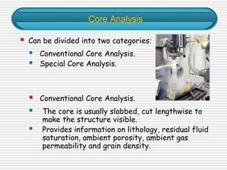
Downloaded 714 times

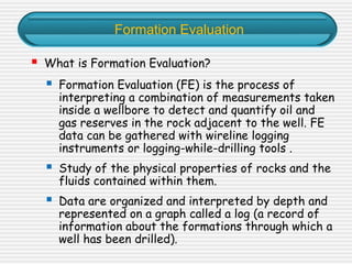


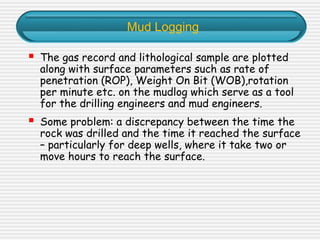


This document provides an overview of formation evaluation techniques used in petroleum exploration and development. It discusses various logging methods like mud logging, coring, open-hole logging using electrical, nuclear and acoustic tools, logging while drilling, formation testing including wireline formation testing and drill stem testing, and cased-hole logging techniques. The goal of formation evaluation is to detect and quantify oil and gas reserves using measurements taken inside the wellbore and interpret physical properties of rocks and contained fluids.


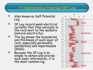
![Well Log Interpretation and Petrophysical Analisis in [Autosaved]](https://cdn.slidesharecdn.com/ss_thumbnails/a24a638f-02ab-4332-9396-89ba2cdd02b4-161128031018-thumbnail.jpg?width=640&height=640&fit=bounds)