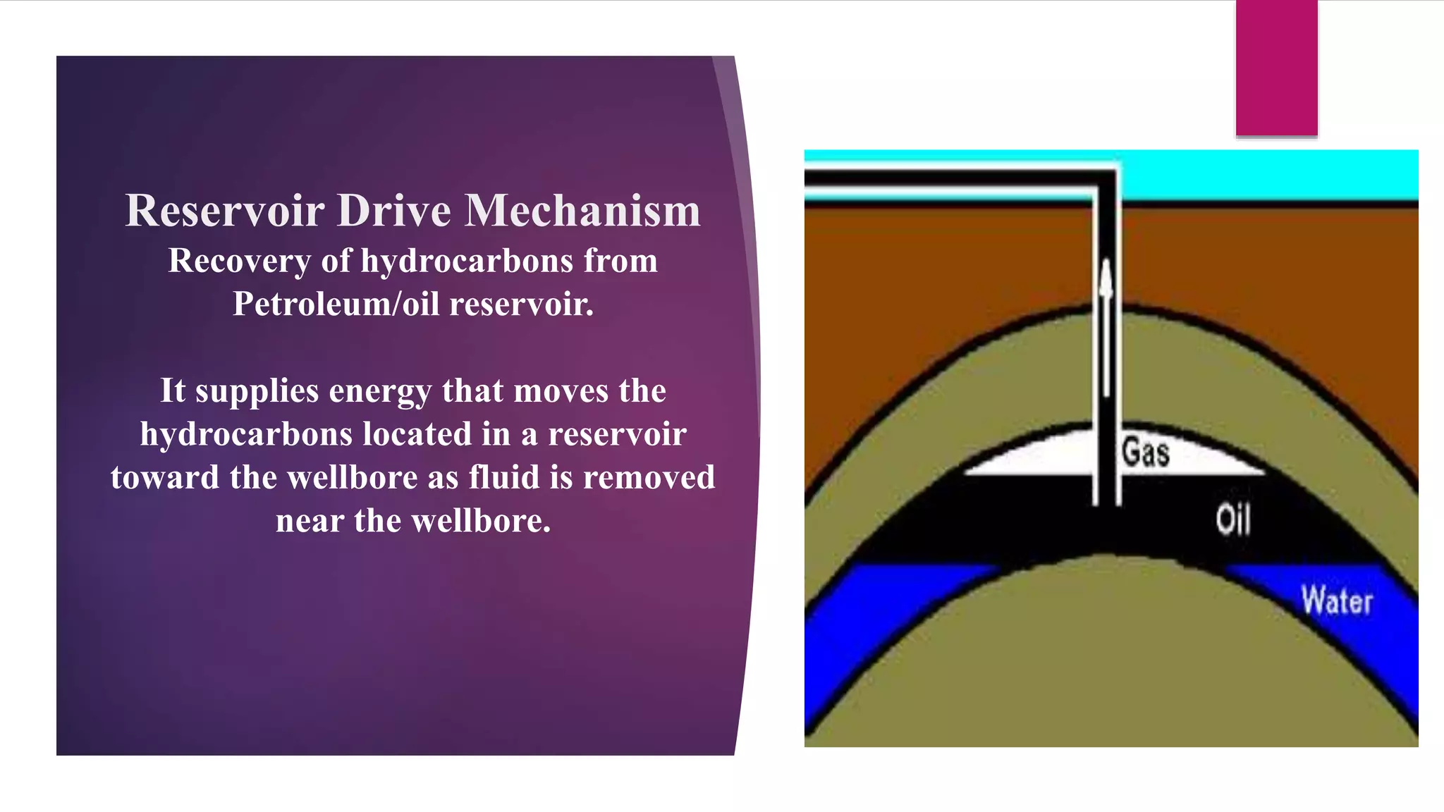
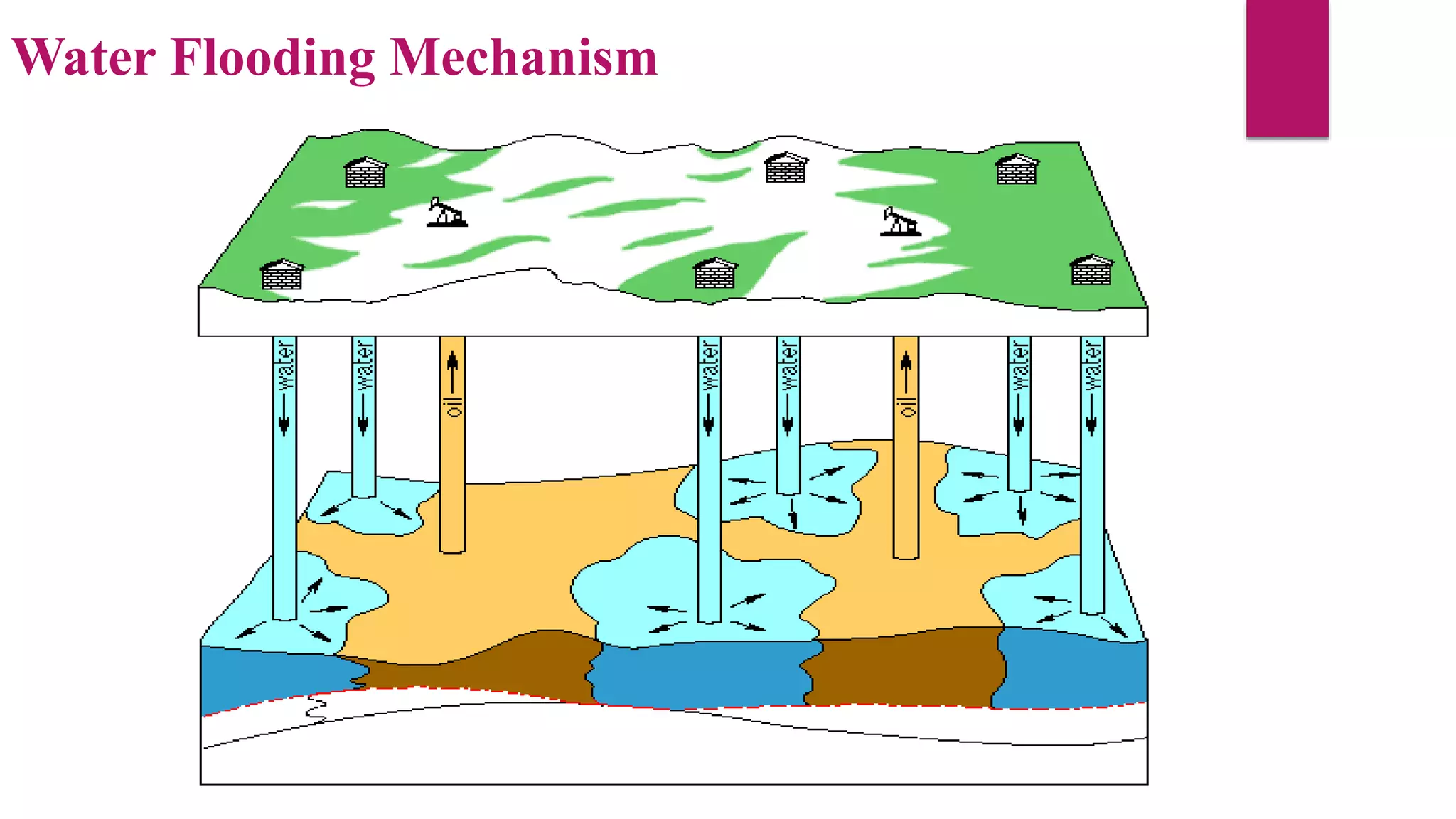
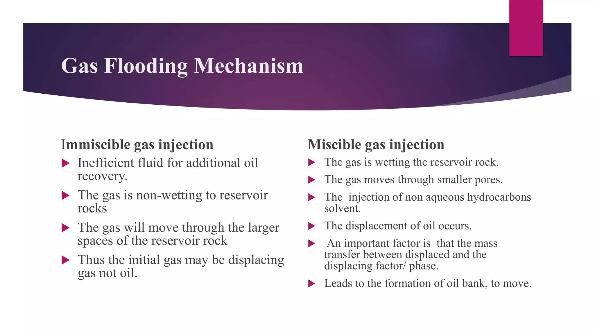
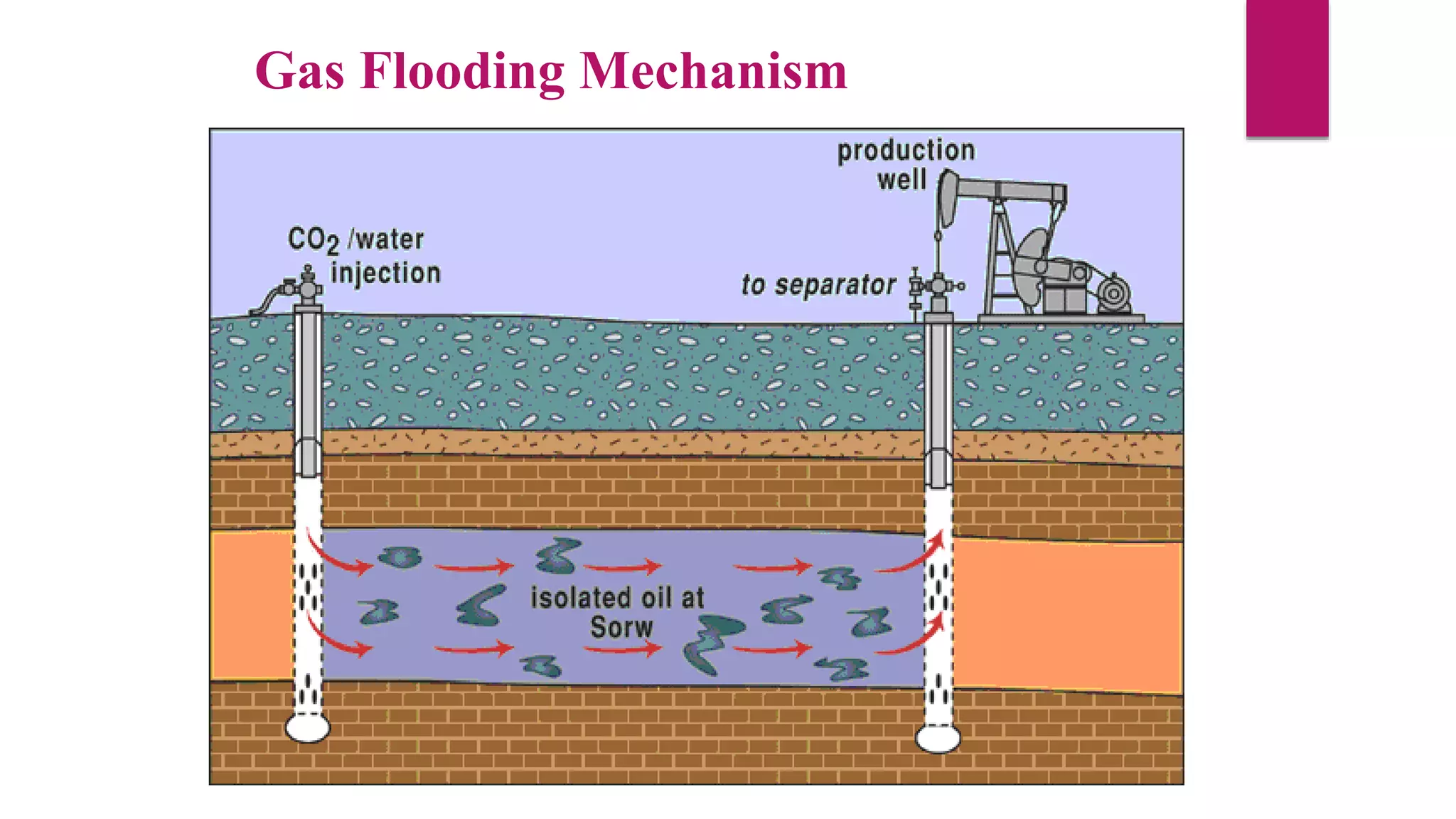
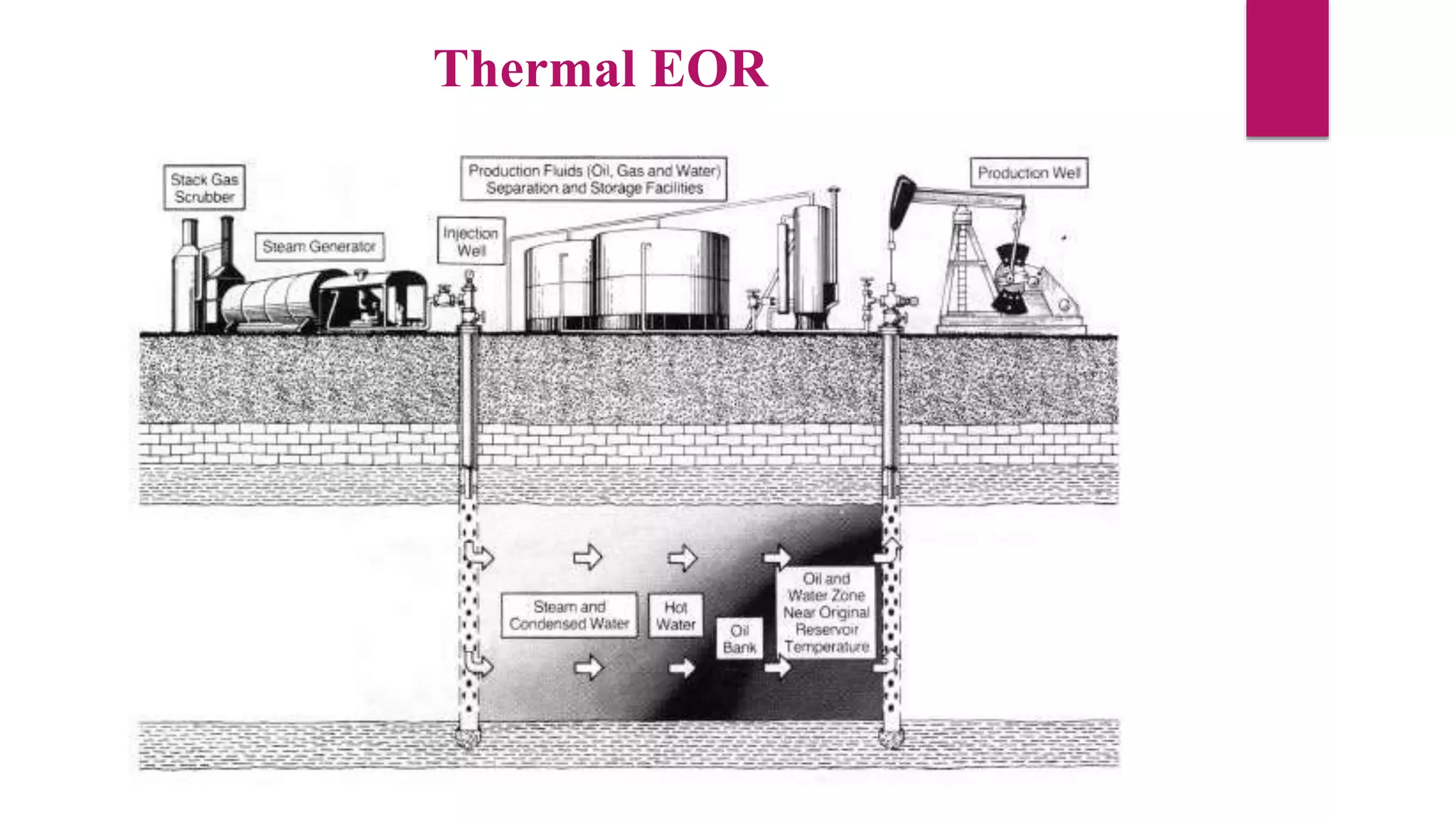
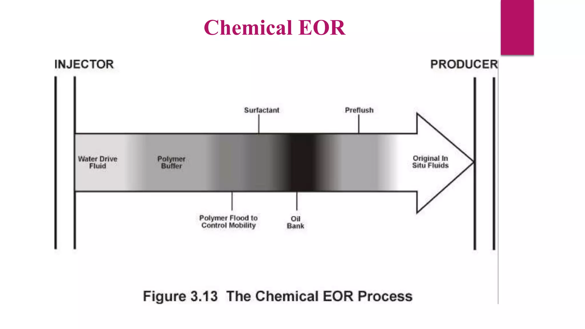
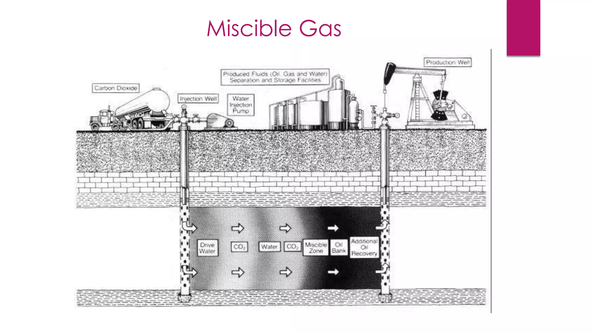
Reservoir Dive
Mechanisms
Group # 2
Group Members
 Umar Khalid 2013-PET-06
 M.Usman Manzoor 2013-PET-05
 Ahsan Ali 2013-PET-08
 Abdi Aziz Rashid 2013-PET-53
 AbdulRahman 2013-PET-07
Discussion Outline
 Definition of Reservoir Drive Mechanism
 Types of Reservoir Drive Mechanisms
 Primary Recovery
 Drive Mechanisms in Primary Recovery
 Secondary Recovery & its Drive Mechanisms
 Tertiary Recovery(EOR) & its Mechanisms
 Infill Recovery
 References
 Overview
 Queries
Reservoir Drive Mechanism
Recovery of hydrocarbons from
Petroleum/oil reservoir.
It supplies energy that moves the
hydrocarbons located in a reservoir
toward the wellbore as fluid is removed
near the wellbore.
Types of Reservoir Drive Mechanism
Recovery of hydrocarbons from an oil reservoir is commonly recognized to
occur in several recovery stages .We use different mechanisms in these
stages.These are :
 Primary recovery
 Secondary recovery
 Tertiary recovery (Enhanced Oil Recovery, EOR)
 Infill recovery
Primary Recovery
 Natural energy of the reservoir works as Drive
 Expansion of original reservoir fluids
 Natural energy is determined by Production data (Reservoir
Pressure and Fluid production Ratios)
 Use of the pressure already in the reservoir
Drive Mechanisms in Primary Recovery
 Solution Gas Drive
 Gas Cap Drive
 Water Drive
 Gravity drainage
 Combination or Mixed Drive
Solution Gas Drive Mechanism
 Reservoir rock surrounded by impermeable barrier.
 At the start of Production, expansion of dissolved gases occur.
 Change in fluid volume results in production of Reservoir fluids.
 A solution gas drive reservoir is initially either considered to be
1. Under saturated
2. Saturated
Solution Gas Drive Mechanism
Oil Recovery from Solution Gas Drive Reservoirs
Initial reservoir
pressure
bubble point pressure
0 5 10 15
reservoir
pressure
(psig)
Dissolved gas
reservoirs typically
recover between 5
and 25% OIIP and
60 to 80% GIIP.
Oil recovery ,% of OOIP
Gas Cap Drive
 Expansion of already present Gas Cap above the reservoir .
 Decrease in pressure during the production, expansion of Gas cap
occur.
 As production continues, the gas cap expands pushing the gas-oil
contact (GOC) downwards.
 Better than Solution gas drive .
 The recovery of gas cap reservoirs is better than for solution drive
reservoirs (20% to 40% OOIP).
Gas cap Drive
Water Drive Mechanism
 Reservoir bounded by aquifers.
 During Pressure Depletion, the compressed water expands and
overflow towards reservoir.
 Invading water drive the oil towards producing wells.
 Water influx acts to mitigate the Pressure Decline.
 The recovery from water driven reservoirs is usually good (20-60%
OOIP)
 Oil recovery from water drive reservoirs typically ranges from 35
to 75% of the original oil in place
Water Drive Mechanism
Gravity Drainage
 Density Differences segregate oil, water and gas .
 Relatively weak mechanism
 Can be used as drive mechanism in combination with other drive mechanism
 The best conditions for gravity drainage are:
1. Thick oil zones.
2. High vertical permeabilities
 Rate of production generated by gravity mechanism is vey low(50-70% OOIP).
 The rate of oil gravity drainage in the reservoir is usually low compared to field
production rates.
Gravity Drainage
Combination or Mixed Drive
 In practice, reservoir usually incorporates at least two main drive
mechanisms.
 The management of the reservoir for different drive mechanisms
can be diametrically opposed.
 For example Gas cap & Aquifer are sometime present together.
 Strength of drives must be identified as early as possible in the life
of reservoir to optimize the reservoirs performance.
Combination or Mixed Drive
Secondary Recovery
 Results from human intervention in the reservoir to improve
recovery after the low efficiencies of Natural /Primary Drive
mechanisms.
 Two techniques are commonly used :
(i) Water flooding
(ii) Gas flooding
Water Flooding Mechanism
 Injection of water in the base of reservoir .
 Water flooding maintain the reservoir pressure.
 Displace oil (usually with gas and water) towards production wells.
 The successful outcome depends on
1. Designs based on accurate relative permeability data in both
horizontal directions,
2. The choice of a good injector/producer array
Water Flooding Mechanism
Gas Flooding Mechanism
 Same as Water Flooding.
 Injection of a gas.
 e.g CO2, N2 or flue gases are generally used.
 Categorized into two types :
1. Immiscible gas injection.
2. Miscible or high-pressure gas injection.
Gas Flooding Mechanism
Immiscible gas injection
 Inefficient fluid for additional oil
recovery.
 The gas is non-wetting to reservoir
rocks
 The gas will move through the larger
spaces of the reservoir rock
 Thus the initial gas may be displacing
gas not oil.
Miscible gas injection
 The gas is wetting the reservoir rock.
 The gas moves through smaller pores.
 The injection of non aqueous hydrocarbons
solvent.
 The displacement of oil occurs.
 An important factor is that the mass
transfer between displaced and the
displacing factor/ phase.
 Leads to the formation of oil bank, to move.
Gas Flooding Mechanism
Tertiary Recovery (EOR)
 Extraction by Primary and Secondary recovery methods is about
35% of the original oil in place.
 Many methods are used:
(i) Thermal
(ii) Chemical
(iii) Miscible gas
Thermal EOR
 Use of heat to improve oil recovery by reducing the viscosity of heavy oils and
vaporising lighter oils and hence improving their mobility.
 This technique includes :
1. Steam injection
2. injection of a hot gas that combusts with the oil in place.
3. Microwave heating downhole
4. Hot water injection.
 thermal EOR is probably the most efficient EOR approach.
Thermal EOR
Chemical EOR
 Use of Chemicals added to water in the injected fluid of a Waterflood to
improve oil recovery.
 This can be done in many ways, examples are listed below:
1. Increasing water viscosity (polymer floods)
2. Decreasing the relative permeability to water (cross-linked polymer
floods)
3. Increasing the relative permeability to oil (micellar and alkaline floods).
4. Decreasing the interfacial tension between the oil and water
phases(micellar and alkaline floods)
Chemical EOR
Miscible Gas
 Uses a fluid that is miscible with the oil
 A fluid has a zero interfacial tension with the oil.
 In practice a gas is used since gases have high mobilities and can easily
enter all the pores in the rock providing the gas is miscible in the oil.
 Three types of gas are commonly used:
1. Carbon di oxide
2. Nitrogen
3. Hydrocarbon gases
 All of these are relatively cheap to obtain..
Miscible Gas
Infill Recovery
 At the end of the reservoir life.
 To improve the production rate.
 To carry out infill drilling,
 Directly accessing oil that may have been left unproduced.
 By using all the previous natural and artificial drive mechanisms.
 Infill drilling can involve very significant drilling costs
 Additional production may not be great.
References
• http://homepages.see.leeds.ac.uk/~earpwjg/PG_EN/CD%20Contents/For
mation%20Evaluation%20English/Chapter%203.PDF
• https://www.metu.edu.tr/~kok/pete110/PETE110_CHAPTER5.pdf
• http://wiki.aapg.org/Drive_mechanisms_and_recovery
• Petroleum Reservoir Engineering ----Basic Concepts
• general view of oil recovery
• https://www.google.com.pk/slideshare
Any Question ??????
Reservoir dive mechanisms

Reservoir dive mechanisms

  • 2.
  • 3.
    Group # 2 GroupMembers  Umar Khalid 2013-PET-06  M.Usman Manzoor 2013-PET-05  Ahsan Ali 2013-PET-08  Abdi Aziz Rashid 2013-PET-53  AbdulRahman 2013-PET-07
  • 4.
    Discussion Outline  Definitionof Reservoir Drive Mechanism  Types of Reservoir Drive Mechanisms  Primary Recovery  Drive Mechanisms in Primary Recovery  Secondary Recovery & its Drive Mechanisms  Tertiary Recovery(EOR) & its Mechanisms  Infill Recovery  References  Overview  Queries
  • 5.
    Reservoir Drive Mechanism Recoveryof hydrocarbons from Petroleum/oil reservoir. It supplies energy that moves the hydrocarbons located in a reservoir toward the wellbore as fluid is removed near the wellbore.
  • 6.
    Types of ReservoirDrive Mechanism Recovery of hydrocarbons from an oil reservoir is commonly recognized to occur in several recovery stages .We use different mechanisms in these stages.These are :  Primary recovery  Secondary recovery  Tertiary recovery (Enhanced Oil Recovery, EOR)  Infill recovery
  • 7.
    Primary Recovery  Naturalenergy of the reservoir works as Drive  Expansion of original reservoir fluids  Natural energy is determined by Production data (Reservoir Pressure and Fluid production Ratios)  Use of the pressure already in the reservoir
  • 8.
    Drive Mechanisms inPrimary Recovery  Solution Gas Drive  Gas Cap Drive  Water Drive  Gravity drainage  Combination or Mixed Drive
  • 9.
    Solution Gas DriveMechanism  Reservoir rock surrounded by impermeable barrier.  At the start of Production, expansion of dissolved gases occur.  Change in fluid volume results in production of Reservoir fluids.  A solution gas drive reservoir is initially either considered to be 1. Under saturated 2. Saturated
  • 10.
  • 11.
    Oil Recovery fromSolution Gas Drive Reservoirs Initial reservoir pressure bubble point pressure 0 5 10 15 reservoir pressure (psig) Dissolved gas reservoirs typically recover between 5 and 25% OIIP and 60 to 80% GIIP. Oil recovery ,% of OOIP
  • 12.
    Gas Cap Drive Expansion of already present Gas Cap above the reservoir .  Decrease in pressure during the production, expansion of Gas cap occur.  As production continues, the gas cap expands pushing the gas-oil contact (GOC) downwards.  Better than Solution gas drive .  The recovery of gas cap reservoirs is better than for solution drive reservoirs (20% to 40% OOIP).
  • 13.
  • 14.
    Water Drive Mechanism Reservoir bounded by aquifers.  During Pressure Depletion, the compressed water expands and overflow towards reservoir.  Invading water drive the oil towards producing wells.  Water influx acts to mitigate the Pressure Decline.  The recovery from water driven reservoirs is usually good (20-60% OOIP)  Oil recovery from water drive reservoirs typically ranges from 35 to 75% of the original oil in place
  • 15.
  • 16.
    Gravity Drainage  DensityDifferences segregate oil, water and gas .  Relatively weak mechanism  Can be used as drive mechanism in combination with other drive mechanism  The best conditions for gravity drainage are: 1. Thick oil zones. 2. High vertical permeabilities  Rate of production generated by gravity mechanism is vey low(50-70% OOIP).  The rate of oil gravity drainage in the reservoir is usually low compared to field production rates.
  • 17.
  • 18.
    Combination or MixedDrive  In practice, reservoir usually incorporates at least two main drive mechanisms.  The management of the reservoir for different drive mechanisms can be diametrically opposed.  For example Gas cap & Aquifer are sometime present together.  Strength of drives must be identified as early as possible in the life of reservoir to optimize the reservoirs performance.
  • 19.
  • 20.
    Secondary Recovery  Resultsfrom human intervention in the reservoir to improve recovery after the low efficiencies of Natural /Primary Drive mechanisms.  Two techniques are commonly used : (i) Water flooding (ii) Gas flooding
  • 21.
    Water Flooding Mechanism Injection of water in the base of reservoir .  Water flooding maintain the reservoir pressure.  Displace oil (usually with gas and water) towards production wells.  The successful outcome depends on 1. Designs based on accurate relative permeability data in both horizontal directions, 2. The choice of a good injector/producer array
  • 22.
  • 23.
    Gas Flooding Mechanism Same as Water Flooding.  Injection of a gas.  e.g CO2, N2 or flue gases are generally used.  Categorized into two types : 1. Immiscible gas injection. 2. Miscible or high-pressure gas injection.
  • 24.
    Gas Flooding Mechanism Immisciblegas injection  Inefficient fluid for additional oil recovery.  The gas is non-wetting to reservoir rocks  The gas will move through the larger spaces of the reservoir rock  Thus the initial gas may be displacing gas not oil. Miscible gas injection  The gas is wetting the reservoir rock.  The gas moves through smaller pores.  The injection of non aqueous hydrocarbons solvent.  The displacement of oil occurs.  An important factor is that the mass transfer between displaced and the displacing factor/ phase.  Leads to the formation of oil bank, to move.
  • 25.
  • 26.
    Tertiary Recovery (EOR) Extraction by Primary and Secondary recovery methods is about 35% of the original oil in place.  Many methods are used: (i) Thermal (ii) Chemical (iii) Miscible gas
  • 27.
    Thermal EOR  Useof heat to improve oil recovery by reducing the viscosity of heavy oils and vaporising lighter oils and hence improving their mobility.  This technique includes : 1. Steam injection 2. injection of a hot gas that combusts with the oil in place. 3. Microwave heating downhole 4. Hot water injection.  thermal EOR is probably the most efficient EOR approach.
  • 28.
  • 29.
    Chemical EOR  Useof Chemicals added to water in the injected fluid of a Waterflood to improve oil recovery.  This can be done in many ways, examples are listed below: 1. Increasing water viscosity (polymer floods) 2. Decreasing the relative permeability to water (cross-linked polymer floods) 3. Increasing the relative permeability to oil (micellar and alkaline floods). 4. Decreasing the interfacial tension between the oil and water phases(micellar and alkaline floods)
  • 30.
  • 31.
    Miscible Gas  Usesa fluid that is miscible with the oil  A fluid has a zero interfacial tension with the oil.  In practice a gas is used since gases have high mobilities and can easily enter all the pores in the rock providing the gas is miscible in the oil.  Three types of gas are commonly used: 1. Carbon di oxide 2. Nitrogen 3. Hydrocarbon gases  All of these are relatively cheap to obtain..
  • 32.
  • 33.
    Infill Recovery  Atthe end of the reservoir life.  To improve the production rate.  To carry out infill drilling,  Directly accessing oil that may have been left unproduced.  By using all the previous natural and artificial drive mechanisms.  Infill drilling can involve very significant drilling costs  Additional production may not be great.
  • 34.
    References • http://homepages.see.leeds.ac.uk/~earpwjg/PG_EN/CD%20Contents/For mation%20Evaluation%20English/Chapter%203.PDF • https://www.metu.edu.tr/~kok/pete110/PETE110_CHAPTER5.pdf •http://wiki.aapg.org/Drive_mechanisms_and_recovery • Petroleum Reservoir Engineering ----Basic Concepts • general view of oil recovery • https://www.google.com.pk/slideshare
  • 35.

Editor's Notes

  • #6 Producing oil and gas needs energy. Usually some of this required energy is supplied by nature. The hydrocarbon fluids are under pressure because of their depth. The gas and water in petroleum reservoirs under pressure are the two main sources that help move the oil to the well bore and sometimes up to the surface. Depending on the original characteristics of hydrocarbon reservoirs, the type of driving energy is different. 
  • #8 Primary recovery This is the recovery of hydrocarbons from the reservoir using the natural energy of the reservoir as a drive. 3.2 Primary Recovery Drive Mechanisms During primary recovery the natural energy of the reservoir is used to transport hydrocarbons towards and out of the production wells. There are several different energy sources, and each gives rise to a drive mechanism. Early in the history of a reservoir the drive mechanism will not be known. It is determined by analysis of production data (reservoir pressure and fluid production ratios). The earliest possible determination of the drive mechanism is a primary goal in the early life of the reservoir, as its knowledge can greatly improve the management and recovery of reserves from the reservoir in its middle and later life.
  • #9 There are five important drive mechanisms (or combinations). These are: (i) Solution gas drive (ii) Gas cap drive (iii) Water drive (iv) Gravity drainage (v) Combination or mixed drive
  • #10 This drive mechanism requires the reservoir rock to be completely surrounded by impermeable barriers. As production occurs the reservoir pressure drops, and the exsolution and expansion of the dissolved gases in the oil and water provide most of the reservoirs drive energy. Small amounts of additional energy are also derived from the expansion of the rock and water, and gas exsolving and The principle of solution gas drive or depletion drive is the expansion of dissolved gas and liquid oil in response to a pressure drop. The change in fluid volume results in production. Above the bubble point, only liquid oil expansion occurs. Below the bubble point, both liquid oil expansion and gas expansion contribute to volume change.The Upper Cretaceous Cardium sand reservoir is an example of a solution gas drive reservoir
  • #13 A gas cap drive reservoir usually benefits to some extent from solution gas drive, but derives its main source of reservoir energy from the expansion of the gas cap already existing above the reservoir. The presence of the expanding gas cap limits the pressure decrease experienced by the reservoir during production. The actual rate of pressure decrease is related to the size of the gas cap. The GOR rises only slowly in the early stages of production from such a reservoir because the pressure of the gas cap prevents gas from coming out of solution in the oil and water. As production continues, the gas cap expands pushing the gas-oil contact (GOC) downwards (Figure 3.4). Eventually the GOC will reach the production wells and the GOR will increase by large amounts (Figures 3.1 and 3.2). The slower reduction in pressure experienced by gas cap reservoirs compared to solution drive reservoirs results in the oil production rates being much higher throughout the life of the reservoir, and needing artificial lift much later than for solution drive reservoirs.
  • #15 petroleum reservoirs are characteristically bounded by and in communication with aquifers. As pressure decreases during pressure depletion, the compressed waters within the aquifers expand and overflow into the petroleum reservoir. The invading water helps drive the oil to the producing wells, leading to improved oil recoveries. Like gas reinjection and gas cap expansion, water influx also acts to mitigate the pressure decline. The degree to which water influx improves oil recovery depends on the size of the adjoining aquifer, the degree of communication between the aquifer and petroleum reservoir, and ultimately the amount of water that encroaches into the reservoir.
  • #19 different drive mechanisms can be diametrically opposeddifferent drive mechanism(e.g. low perforation for gascap reservoirs comparedwith high perforation for water drive reservoirs). If both occur as in Figure 3.8, a compromise must be sought, and this compromise must take into account the strength of each drive present, the size of the gas cap, and the size/permeability of the aquifer. It is the job of the reservoir manager to identifythe strengths of the drives as early as possible in the life of the reservoir to optimise the reservoir performance.
  • #20 different drive mechanisms can be diametrically opposeddifferent drive mechanism(e.g. low perforation for gascap reservoirs comparedwith high perforation for water drive reservoirs). If both occur as in Figure 3.8, a compromise must be sought, and this compromise must take into account the strength of each drive present, the size of the gas cap, and the size/permeability of the aquifer. It is the job of the reservoir manager to identifythe strengths of the drives as early as possible in the life of the reservoir to optimise the reservoir performance.
  • #22 Waterflooding This method involves the injection of water at the base of a reservoir to; (i) Maintain the reservoir pressure, and (ii) Displace oil (usually with gas and water) towards production wells. The detailed treatment of waterflood recovery estimation, mathematical modelling, and design are beyond the scope of these notes. However, it should be noted that the successful outcome of a waterflood process depends on designs based on accurate relative permeability data in both horizontal directions, on the choice of a good injector/producer array, and with full account taken of the local crustal stress directions in the reservoir
  • #24 Gas Injection This method is similar to waterflooding in principal, and is used to maintain gas cap pressure even if oil displacement is not required. Again accurate relperms are needed in the design, as well as injector/producer array geometry and crustal stresses. There is an additional complication in that re-injected lean gas may strip light hydrocarbons from the liquid oil phase. At first sight this may not seem a problem, as recombination in the stock tank or afterwards may be carried out. However, equity agreements often give different percentages of gas and oil to different companies. Then the decision whether to gasflood is not trivial (e.g. Prudhoe Bay, Alaska)
  • #25 Immiscible gas injection It is very inefficient fluid for additional oil recovery. The gas is non-wetting to reservoir rocks. The gas will move through the larger spaces of the reservoir rock by passing much of the reservoir oil. Some gas saturation will be present.   moves through the formation moves through the formation Miscible or high-pressure gas injection The displacement of oil by non aqueous injected of hydrocarbons solvent, lean hydrocarbon gases, such as CO2, N2 or flue gases are generally described as miscible fluids. The various conditions of pressure and temperature that are required for miscibility whether on first multiple contact or normally dealt. An important factor in oil recovery process is that the mass transfer between displaced and the displacing factor/ phase. In multiple contact system residual oil behind displace center may stripped of light and intermediate fraction reducing substantially the residual oil saturation. This is known as vaporization gas drive. Another mechanism called condensing gas drive involves the transfer of intermediate components from the displacing gas to the residual oil. The residual oil becomes of a lower viscosity and has increase oil permeability. These volume effects can be significant even when full miscibility is not attempt. In an ideal process the swelling and the mobilization dispersed the discontinuous residual oil phase. Leads to the formation of oil bank which, may then itself seam residual oil as it moves through the formation. Tripping behind the oil bank is prevented by miscible condition or by very large capillary number, where the formation is connected by the miscible solvent it is expected that the oil recovery is complete.
  • #28 These processes use heat to improve oil recovery by reducing the viscosity of heavy oils and vaporising lighter oils, and hence improving their mobility. The techniques include: (i) Steam injection (Figure 3.9). (ii) In situ combustion (injection of a hot gas that combusts with the oil in place, Figure 3.10). (iii) Microwave heating downhole (3.11). (iv) Hot water injection. It is worth noting that the generation of large amounts of heat and the treatment of evolved gas has large environmental implications for these methods. However, thermal EOR is probably the most efficient EOR approach.
  • #29 These processes use heat to improve oil recovery by reducing the viscosity of heavy oils and vaporising lighter oils, and hence improving their mobility. The techniques include: (i) Steam injection (Figure 3.9). (ii) In situ combustion (injection of a hot gas that combusts with the oil in place, Figure 3.10). (iii) Microwave heating downhole (3.11). (iv) Hot water injection. It is worth noting that the generation of large amounts of heat and the treatment of evolved gas has large environmental implications for these methods. However, thermal EOR is probably the most efficient EOR approach.
  • #30 Chemical EOR These processes use chemicals added to water in the injected fluid of a waterflood to alter the flood efficiency in such a way as to improve oil recovery. This can be done in many ways, examples are listed below: (i) Increasing water viscosity (polymer floods) (ii) Decreasing the relative permeability to water (cross-linked polymer floods) (iii) Increasing the relative permeability to oil (micellar and alkaline floods)
  • #32 Miscible Gas Flooding This method uses a fluid that is miscible with the oil. Such a fluid has a zero interfacial tension with the oil and can in principal flush out all of the oil remaining in place. In practice a gas is used since gases have high mobilities and can easily enter all the pores in the rock providing the gas is miscible in the oil. Three types of gas are commonly used: (i) CO2 (ii) N2 (iii) Hydrocarbon gases.