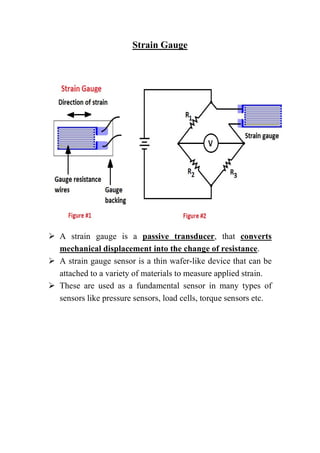
Strain Gauge
 A strain gauge is a passive transducer, that converts
mechanical displacement into the change of resistance.
 A strain gauge sensor is a thin wafer-like device that can be
attached to a variety of materials to measure applied strain.
 These are used as a fundamental sensor in many types of
sensors like pressure sensors, load cells, torque sensors etc.
 Working Principle :-
Here = Resistivity
 The resistance of the foil changes as the material to which
the gauge is attached undergoes tension or compression due
to change in its length and diameter. As length changes the
Resistance Changes due to the above formula.
 This change in resistance is proportional to the applied
strain.
 As this change in resistance is very small in magnitude so its
effect can be only sensed by a Wheatstone bridge. This is the
basic strain gauge working principle.
 A circuit diagram is shown in Figure #2. In this circuit
diagram, a strain gauge is connected into a Wheatstone
bridge.
 This circuit is so designed that when no force is applied to
the strain gauge, R1 is equal to R2 and the resistance of the
strain gauge is equal to R3.
 In this condition the Wheatstone bridge is balanced and the
voltmeter shows no deflection.
 But when strain is applied to the strain gauge, the resistance
of the strain gauge sensor changes, the Wheatstone bridge
becomes unbalanced, a current flows through the voltmeter.
 Since the net change in the resistance is proportional to the
applied strain, therefore, resultant current flow through the
voltmeter is proportional to the applied strain.
 So, the voltmeter can be calibrated in terms of strain or force.
 In the above circuit, we have used only one strain gauge.
This is known as ‘quarter bridge’ circuit.
 We can also use two strain gauges or even four strain gauges
in this circuit.
 Then this circuit is called ‘half bridge’ and ‘full bridge’
respectively.
 The full bridge circuit provides greater sensitivity and least
temperature variation errors.
 Gauge Factor of Strain Gauge :-
 The gauge factor of strain gauge is defined as the unit
change in resistance per unit change in length.
gauge factor Gf = (∆R/R)/( ∆l/l)
where, R = nominal gauge resistance,
∆R = change in resistance,
l = length of the specimen in an unstressed condition,
∆l = change in specimen length.
It can be proved mathematically,
Gauge factor, Gf = 1 + 2v + (∆ρ/ρ)/(∆L/L)
If the change in resistivity due to strain is almost negligible, then
gauge factor of strain gauge, Gf = 1 + 2v
 Where, v is Poisson’s ratio.
 It may be defined as the ratio of strain in the lateral direction
to the strain in the axial direction.
 The Poisson’s ratio for most metals lies in the range of 0 to
0.5 and this gives a gauge factor of 2 approximately.
Wireless Strain SenSpot™ sensors
 Wireless Strain SenSpot™ sensors offer a breakthrough
technology for real-time and long-term structural health
monitoring.
 SenSpot™ strain gauge uses Resensys’s proprietary sensing,
scheduling and ultra-low power synchronization technology.
 SenSpot™ is designed to operate maintenance-free for more
than a decade. After installation, SenSpot™ does not need
calibration, battery replacement, or any other maintenance
during its entire service life.
 Features
1. Long lifetime: (minimum expected life without battery
replacement 10 years)
2. Lightweight: about 147 g (5.19 oz.)
3. Wireless transmitter: 120 g (4.23 oz.)
4. Cable (1ft): 10 g (0.35oz.)
5. Strain sensing element: 17 g (0.6 oz.)
6. Easy mounting
a) Self-adhesive, no drilling is required (e.g. steel)
b)Flange-mount, drilling is required (e.g. concrete)
c) Quick installation, 1-2 minutes
7. High accuracy: 1-µStrain resolution
8. Wide working temperature: -40 to +65°C (-40 °F to +150°F)
9. Long communication range: 1.0km free space
 References :-
1. http://www.resensys.com/senspot-
strain.html?gclid=CjwKCAiAl-
6PBhBCEiwAc2GOVL_k7fgHEOciMFCqiNAewcjJk_snv
W3g4Pr5kbjSpt_GRQBM3xOOghoCC_4QAvD_BwE
2. https://www.electrical4u.com/strain-gauge/

Strain gauge

  • 1.
    Strain Gauge  Astrain gauge is a passive transducer, that converts mechanical displacement into the change of resistance.  A strain gauge sensor is a thin wafer-like device that can be attached to a variety of materials to measure applied strain.  These are used as a fundamental sensor in many types of sensors like pressure sensors, load cells, torque sensors etc.
  • 2.
     Working Principle:- Here = Resistivity  The resistance of the foil changes as the material to which the gauge is attached undergoes tension or compression due to change in its length and diameter. As length changes the Resistance Changes due to the above formula.  This change in resistance is proportional to the applied strain.  As this change in resistance is very small in magnitude so its effect can be only sensed by a Wheatstone bridge. This is the basic strain gauge working principle.  A circuit diagram is shown in Figure #2. In this circuit diagram, a strain gauge is connected into a Wheatstone bridge.  This circuit is so designed that when no force is applied to the strain gauge, R1 is equal to R2 and the resistance of the strain gauge is equal to R3.  In this condition the Wheatstone bridge is balanced and the voltmeter shows no deflection.
  • 3.
     But whenstrain is applied to the strain gauge, the resistance of the strain gauge sensor changes, the Wheatstone bridge becomes unbalanced, a current flows through the voltmeter.  Since the net change in the resistance is proportional to the applied strain, therefore, resultant current flow through the voltmeter is proportional to the applied strain.  So, the voltmeter can be calibrated in terms of strain or force.  In the above circuit, we have used only one strain gauge. This is known as ‘quarter bridge’ circuit.  We can also use two strain gauges or even four strain gauges in this circuit.  Then this circuit is called ‘half bridge’ and ‘full bridge’ respectively.  The full bridge circuit provides greater sensitivity and least temperature variation errors.  Gauge Factor of Strain Gauge :-  The gauge factor of strain gauge is defined as the unit change in resistance per unit change in length. gauge factor Gf = (∆R/R)/( ∆l/l) where, R = nominal gauge resistance, ∆R = change in resistance, l = length of the specimen in an unstressed condition, ∆l = change in specimen length. It can be proved mathematically,
  • 4.
    Gauge factor, Gf= 1 + 2v + (∆ρ/ρ)/(∆L/L) If the change in resistivity due to strain is almost negligible, then gauge factor of strain gauge, Gf = 1 + 2v  Where, v is Poisson’s ratio.  It may be defined as the ratio of strain in the lateral direction to the strain in the axial direction.  The Poisson’s ratio for most metals lies in the range of 0 to 0.5 and this gives a gauge factor of 2 approximately.
  • 5.
    Wireless Strain SenSpot™sensors  Wireless Strain SenSpot™ sensors offer a breakthrough technology for real-time and long-term structural health monitoring.  SenSpot™ strain gauge uses Resensys’s proprietary sensing, scheduling and ultra-low power synchronization technology.  SenSpot™ is designed to operate maintenance-free for more than a decade. After installation, SenSpot™ does not need calibration, battery replacement, or any other maintenance during its entire service life.  Features 1. Long lifetime: (minimum expected life without battery replacement 10 years) 2. Lightweight: about 147 g (5.19 oz.) 3. Wireless transmitter: 120 g (4.23 oz.) 4. Cable (1ft): 10 g (0.35oz.) 5. Strain sensing element: 17 g (0.6 oz.) 6. Easy mounting a) Self-adhesive, no drilling is required (e.g. steel) b)Flange-mount, drilling is required (e.g. concrete) c) Quick installation, 1-2 minutes 7. High accuracy: 1-µStrain resolution 8. Wide working temperature: -40 to +65°C (-40 °F to +150°F) 9. Long communication range: 1.0km free space
  • 6.
     References :- 1.http://www.resensys.com/senspot- strain.html?gclid=CjwKCAiAl- 6PBhBCEiwAc2GOVL_k7fgHEOciMFCqiNAewcjJk_snv W3g4Pr5kbjSpt_GRQBM3xOOghoCC_4QAvD_BwE 2. https://www.electrical4u.com/strain-gauge/