SlideShare a Scribd company logo
1 of 21
6.7 Instrument and Control
6.7.1 Instrument
All machinery must operate within certain desired parameters. Instrumentation enables the
parameters, such as temperature and pressure, to be measured or displayed against a scale. A
means of control is also required in order to change or alter the displayed readings to meet
particular requirements. The main parameters include the measurement of pressure,
temperature, liquid level, fl ow rate, torque, salinity and oxygen content. The various devices
used for measurement of system parameters are
described by McGeorge (1995) and Taylor (1996) . The following Sections describe briefl y the
theory and application of automatic control.
6.7.2 Control
6.7.2.1 Control Theory
To control a device or system is to be able to adjust or vary the parameters which affect it.
This can be achieved manually or automatically, depending upon the arrangements made in the
system. All forms of control can be considered to act in a loop. The basic elements present in
the loop are a detector, a comparator/controller and a correcting unit, all of which surround
the process and form the loop ( Figure 6.111 ). This arrangement is an automatic closed loop if
the elements are directly connected to one another and the control action takes place without
human involvement. A manual closed loop would exist if one element were replaced by a
human operator.
It can be seen therefore that in a closed loop control system the control action is dependent
on the output. A detecting or measuring element will obtain a signal related to this output
which is fed to the transmitter. From the transmitter the signal is then passed to a comparator.
The comparator will contain some set or desired value of the controlled condition which is
compared to the measured value signal. Any deviation or difference between the two values
will result in an output signal to the controller. The controller will then take action in a manner
related to the deviation and provide a signal to a correcting
unit. The correcting unit will then increase or decrease its effect on the system to achieve the
desired value of the system variable. The comparator is usually built in to the controller unit.
The transmitter, controller and regulating unit are supplied with an operating medium in
order to function. The operating medium may be compressed air, hydraulic oil or electricity. For
each medium various types of transmitting devices, controllers and regulating units are used.
Detailed accounts of control theory and marine control systems can be found in Fossen (2002)
and Perez (2005) .
6.7.2.2 Transmitters
Pneumatic Many pneumatic devices use a nozzle and fl apper system to give a variation in
the compressed air signal. A pneumatic transmitter is shown in Figure 6.112 . If the fl apper
moves away from the nozzle then the transmitted or output pressure will fall to a low value. If
the fl apper moves towards the nozzle then the transmitted pressure will rise to almost the
supply pressure. The transmitted pressure is approximately proportional to the movement of
the fl apper and thus the change in the measured variable. The fl apper movement will be very
minute and where measurement of a reasonable movement is necessary a system of levers and
linkages must be introduced. This in turn leads to errors in the system and little more than on-
off control. Improved accuracy is obtained when a feedback bellows is added to assist in fl
apper positioning ( Figure 6.113 ). The measured value acts on one end
of the pivoted fl apper against an adjustable spring which enables the measuring range to be
changed. The opposite end of the fl apper is acted upon by the feedback bellows and the
nozzle. In operation a change in the measured variable may cause the fl apper to approach the
nozzle and thus build up the output signal pressure. The pressure in the feedback bellows also
builds up, tending to push the fl apper away from the nozzle, i.e. a negative feedback. An
equilibrium position will be set up giving an output signal corresponding to the measured
variable. Most pneumatic transmitters will have relays fitted which magnify or amplify the
output signals to reduce time lags in the system and permit signal transmission over
considerable distances. Relays can also be used for mathematical operations, such as adding,
subtracting, multiplying or dividing of signals. Such devices are known as ‘ summing ’ or ‘
computing relays ’ .
Electrical
Simple electrical circuits may be used where the measured variable causes a change in
resistance which is read as a voltage or current and displayed in its appropriate units. Another
method is where the measured variable in changing creates a potential difference which, after
amplifi cation, drives a reversible motor to provide a display and in moving also reduces the
potential difference to zero. Alternating current positioning motors can be used as transmitters
when arranged as shown in Figure 6.114. Both rotors are supplied from the same supply
source. The stators are star wound and when the two rotor positions coincide there is no
current fl ow since the e.m.f.s of both are equal and opposite. When the measured variable
causes a change in the transmitter rotor position, the two e.m.f.s will be out of balance. A
current will fl ow and the receiver
rotor will turn until it aligns with the transmitter. The receiver rotor movement will provide a
display of the measured variable.
An electrical device can also be used as a transmitter ( Figure 6.115 ). The measured variable
acts on one end of a pivoted beam causing a change in a magnetic circuit. The change in the
magnetic circuit results in a change in output current from the oscillator amplifi er, and the
oscillator output current operates an electromagnet so that it produces a negative feedback
force which opposes the measured variable change. An equilibrium position results and
provides an output signal.
Hydraulic
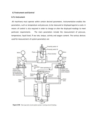
The telemotor of a hydraulically actuated steering gear is one example of a hydraulic
transmitter. A complete description of the unit and its operation is given in Section 6.6.3.
6.7.2.3 Controller Action
The transmitted output signal is received by the controller which must then undertake some
corrective action. There will however be various time lags or delays occurring during fi rst the
measuring and then the transmission of a signal indicating a change. A delay will also occur in
the action of the controller. These delays produce what is known as the transfer function of the
unit or item, that is, the relationship between the output and input signals.
The control system is designed to maintain some output value at a constant desired value,
and a knowledge of the various lags or delays in the system is necessary in order to achieve the
desired control. The controller must therefore rapidly compensate for these system variations
and ensure a steady output as near to the desired value as practicable.
Two-step or on-off
In this, the simplest of controller actions, two extreme positions of the controller are possible,
either on or off. If the controller were, for example, a valve it would be either open or closed. A
heating system is considered with the control valve regulating the supply of heating steam. The
controller action and system response is shown in Figure 6.116 . As the measured value rises
above its desired value the valve will close. System lags will result in a continuing temperature
rise which eventually peaks and then falls below the desired value. The valve will then open
again and the temperature will cease to fall and will rise again. This form of control is
acceptable where a considerable deviation from the desired value is allowed.
Continuous action
Proportional action . This is a form of continuous control where any change in controller
output is proportional to the deviation between the controlled condition and the desired value.
The proportional band is the amount by which the input signal value must change to move the
correcting unit between its extreme positions. The desired value is usually located at the centre
of the proportional band. Offset is a sustained deviation as a result of a load change in the
process. It is an inherent characteristic of proportional control action. Consider, for example, a
proportional controller operating a feedwater valve supplying a boiler drum. If the steam
demand, i.e. load, increases then the drum level will fall. When the level has dropped the
feedwater valve will open. An equilibrium position will be reached when the feedwater valve
has opened enough to match the new steam demand. The drum level, however, will
have fallen to a new value below the desired value, i.e. offset. See Figure 6.117.
Integral action . This type of controller action is used in conjunction with proportional control
in order to remove offset. Integral or reset action occurs when the controller output varies at a
rate proportional to the deviation between the desired value and the measured value. The
integral action of a controller can usually be varied to achieve the required response in a
particular system.
Derivative action . Where a plant or system has long time delays between changes in the
measured value and their correction, derivative action may be applied. This will be in addition
to proportional and integral action. Derivative or rate action is where the output signal change
is proportional to the rate of change of deviation. A considerable corrective action can
therefore take place for a small deviation which occurs suddenly. Derivative action can also be
adjusted within the controller.
Multiple-term controllers . The various controller actions in response to a process change are
shown in Figure 6.118 . The improvement in response associated with the addition of integral
and derivative action can clearly be seen. Reference is often made to the number of terms of a
controller. This means the various actions: proportional (P), integral (I), and derivative (D). A
three-term controller would therefore mean P +I + D, and two-term usually P + I. A controller
may be arranged to provide either split range or cascade control, depending upon the
arrangements in the control system. These two types of control are described in the section
dealing with control systems.
6.7.2.4 Controllers
The controller may be located close to the variable measuring point and thus operate without
the use of a transmitter. It may however be located in a remote control room and receive a
signal from a transmitter and relay, as mentioned earlier. The controller is required to maintain
some system variable at a desired value regardless of load changes. It may also indicate the
system variable and enable the desired value to be changed. Over a short range about the
desired value the controller will generate a signal to operate the actuating mechanism of the
correcting unit. This control signal may include proportional, integral and derivative actions, as
already described. Where all three are used it may be known as a ‘ threeterm’ controller.
A pneumatic three-term controller is shown in Figure 6.119 . Any variation between desired
and measured values will result in a movement of the fl apper and change in the output
pressure. If the derivative action valve is open and the integral action valve closed, then only
proportional control occurs. It can be seen that as the fl apper moves towards the nozzle a
pressure build-up will occur which will increase the output pressure signal and also move the
bellows so that the fl apper is moved away from the nozzle. This is then a negative feedback
which is proportional to the fl apper or measured value movement. When the integral action
valve is opened, any change in output signal pressure will affect the integral action bellows
which will oppose the feedback bellows movement. Varying the opening of the integral action
valve will alter the amount of integral action of the controller. Closing the derivative action
valve any amount would introduce derivative action. This is because of the delay that would be
introduced in the provision of negative feedback for a sudden variable change which would
enable the output signal pressure to build up. If the measured variable were to change slowly
then the proportional action would have time to build up and thus exert its effect.
An electronic three-term controller is shown in Figure 6.120 . The controller output signal is
subjected to the various control actions, in this case by electronic components and suitable
circuits. Any change in the measured value will move the input potentiometer and upset the
balance of the control bridge. A voltage will then be applied to the amplifi er and the amplifi er
will provide an output signal which will result in a movement of the output potentiometer. The
balancing bridge will then provide a voltage to the amplifi er which equals that from the control
bridge. The amplifi er output signal will then cease.
The output potentiometer movement is proportional to the deviation between potentiometer
positions, and movement will continue while the deviation remains. Integral and derivative
actions are obtained by the resistances and capacitors in the circuit. With the integral capacitor
fi tted while a deviation exists there will be a current through resistance R as a result of the
voltage across it. This current fl ow will charge the integral capacitor and thus reduce the
voltage across R. The output
potentiometer must therefore continue moving until no deviation exists. No offset can occur as
it would if only proportional action took place. Derivative action occurs as a result of current fl
ow through the derivative resistor which also charges the derivative capacitor. This current fl
ow occurs only while the balancing bridge voltage is changing, but a larger voltage is required
because of the derivative capacitor. The derivative action thus results in a faster return to the
equilibrium position, as would be expected. The output potentiometer is moved by a motor
which also provides movement for a valve or other correcting unit in the controlled process.
6.7.2.5 Correcting unit
The controller output signal is fed to the correcting unit which then alters some variable in
order to return the system to its desired value. This correcting unit may be a valve, a motor, a
damper or louvre for a fan or an electric contactor. Most marine control applications will
involve the actuation or operation of valves in order to regulate liquid fl ow.
Pneumatic control valve
A typical pneumatic control valve is shown in Figure 6.121 . It can be considered as made up
of two parts—the actuator and the valve. In the arrangement shown a fl exible diaphragm
forms a pressure tight chamber in the upper half of the actuator and the controller signal is fed
in. Movement of the diaphragm results in a movement of the valve spindle and the valve. The
diaphragm movement is opposed by a spring and is usually arranged so that the variation of
controller output corresponds to full travel of the valve.
The valve body is arranged to fi t into the particular pipeline and houses the valve and seat
assembly. Valve operation may be direct acting where increasing pressure on the diaphragm
closes the valve. A reverse acting valve opens as pressure on the diaphragm increases. The
diaphragm movement is opposed by a spring which will close or open the valve in the event of
air supply failure depending upon the action of the valve.
The valve disc or plug may be single or double seated and have any of a variety of shapes. The
various shapes and types are chosen according to the type of control required and the
relationship between valve lift and liquid fl ow.
A non-adjustable gland arrangement is usual. Inverted V-ring packing is used to minimize the
friction against the moving spindle.
In order to achieve accurate valve disc positioning and overcome the effects of friction and
unbalanced
Figure 6.121 Pneumatically controlled valve.
forces a valve positioner may be used. The operating principle is shown in Figure 6.122 . The
controller signal acts on a bellows which will move the fl apper in relation to the nozzle. This
movement will alter the air pressure on the diaphragm which is supplied via an orifi ce from a
constant pressure supply. The diaphragm movement will move the valve spindle and also the fl
apper. An equilibrium position will be set up when the valve disc is correctly positioned. This
arrangement enables the use of a separate power source to actuate the valve.
Actuator operation
The control signal to a correcting unit may be pneumatic, electric or hydraulic. The actuating
power may also be any one of these three and not necessarily the same as the control medium.
Electrical control signals are usually of small voltage or current values which are unable to
effect actuator movement. Pneumatic or hydraulic power would then be used for actuator
operation.
A separate pneumatic power supply may be used even when the control signal is pneumatic,
as described in the previous section.
Hydraulic actuator power is used where large or out of balance forces occur or when the
correct ing unit is of large dimensions itself. Hydraulic control with separate hydraulic actuation
is a feature of some types of steering gear, as mentioned in Section 6.6.3.
6.7.2.6 Control system
Boiler water level
A modern high pressure, high temperature watertube boiler holds a small quantity of water
and produces large quantities of steam. Very careful control of the drum water level is
therefore necessary. The reactions of steam and water in the drum are complicated and require
a control system based on a number of measured elements.
When a boiler is operating the water level in the gauge glass reads higher than when the
boiler is shut down. This is because of the presence of steam bubbles in the water, a situation
which is accepted in normal practice. If however there occurs a sudden increase in steam
demand from the boiler the pressure in the drum will fall. Some of the water present in the
drum at the higher pressure will now ‘ fl ash off ’ and become steam. These bubbles of steam
will cause the drum level to rise. The reduced mass of water in the drum will also result in more
steam being produced, which will further raise the water level. This effect is known as ‘ swell ’ .
A level control system which used only level as a measuring element would close in the feed
control valve—when it should be opening it.
When the boiler load returns to normal the drum pressure will rise and steam bubble
formation will reduce, causing a fall in water level. Incoming colder feed water will further
reduce steam bubble formation and what is known as ‘ shrinkage ’ of the drum level will occur.
The problems associated with swell and shrinkage are removed by the use of a second
measuring element, ‘ steam fl ow ’ . A third element, ‘feed water flow ’ , is added to avoid
problems that would occur if the feed water pressure were to vary.
A three element control system is shown in Figure 6.123 . The measured variables or
elements are ‘ steam flow ’ , ‘ drum level ’ and ‘feed water fl ow ’ . Since in a balanced
situation steam fl ow must equal feed flow, these two signals are compared in a differential
relay. The relay output is fed to a two-term controller and comparator into which the measured
drum level signal is also fed. Any deviation between the desired and actual drum level and any
deviation between feed and steam fl ow will result in controller action to adjust the feed water
control valve. The drum level will then be returned to its correct position.
A sudden increase in steam demand would result in a deviation signal from the differential
relay and an output signal to open the feed water control valve. The swell effect would
therefore not infl uence the correct operation of the control system. For a reduction in steam
demand, an output signal to close the feed water control valve would result, thus avoiding
shrinkage effects. Any change in feed water pressure would result in feed water control valve
movement to correct the change before the drum level was affected.
Exhaust steam pressure control
Exhaust steam for various auxiliary services may be controlled at constant pressure by
appropriate operation of a surplus steam (dump) valve or a make-up steam valve. A single
controller can be used to operate one valve or the other in what is known as ‘ split range
control ’.
The control arrangement is shown in Figure 6.124 . The steam pressure in the auxiliary range
is measured by a pressure transmitter. This signal is fed to the controller where it is compared
with the desired value. The two-term controller will
provide an output signal which is fed to both control valves. Each valve is operated by a
different range of pressure with a ‘ dead band ’ between the ranges so that only one valve is
ever open at a time. The arrangement is shown in Figure 6.124 . Thus if the auxiliary range
pressure is high the dump valve opens to release steam. If the pressure is low the make-up
valve opens to admit steam.
This split range control principle can be applied to a number of valves if the controller output
range is split appropriately.
Steam temperature control
Steam temperature control of high pressure superheated steam is necessary to avoid damage
to the metals used in a steam turbine.
One method of control is shown in Figure 6.125. Steam from the primary superheater may be
directed to a boiler drum attemperator where its temperature will be reduced. This steam will
then be further heated in the secondary superheater. The steam temperature leaving the
secondary superheater is measured and transmitted to a three-term controller which also acts
as a comparator. Any deviation from the desired value will result in a signal to a summing relay.
The other signal to the relay is from a steam fl ow measuring element. The relay output signal
provides control of the coupled attemperator inlet and bypass valves. As a result the steam fl
ow is proportioned between the attemperator and the straight through line. This two-element
control system can adequately deal with changing conditions. If, for example, the steam
demand suddenly increased a fall in steam temperature might occur. The steam fl ow element
will however detect the load change and adjust the amount of steam attemperated to maintain
the correct steam temperature.
Boiler combustion control
The essential requirement for a combustion control system is to correctly proportion the
quantities of air and fuel being burnt. This will ensure complete combustion, a minimum of
excess air and acceptable exhaust gases. The control system must therefore measure the fl ow
rates of fuel oil and air in order to correctly regulate their proportions.
A combustion control system capable of accepting rapid load changes is shown in Figure
6.126. Two
control elements are used, ‘steam flow ’ and‘steam pressure ’. The steam pressure signal is fed
to a twoterm controller and is compared with the desired value. Any deviation results in a
signal to the summing relay.
The steam fl ow signal is also fed into the summing relay. The summing relay which may add
or subtract the input signals provides an output which represents the fuel input requirements
of the boiler. This output becomes a variable desired value signal to the two term controllers in
the fuel control and combustion air control loops. A high or low signal selector is present to
ensure that when a load change occurs the combustion air flow is always in excess of the fuel
requirements. This prevents poor combustion and black smokey exhaust gases. If the master
signal is for an increase in steam flow, then when it is fed to the low signal selector it is blocked
since it is the higher input value. When the master signal is input to the high signal selector it
passes through as the higher input. This master signal now acts as a variable desired value for
the combustion air subloop and brings about an increased air flow. When the increased air fl
ow is established its measured value is now the higher input to the low signal selector. The
master signal will now pass through to bring about the increased fuel supply to the boiler via
the fuel supply sub-loop. The air supply for an increase in load is therefore established before
the increase in fuel supply occurs. The required air to fuel ratio is set in the ratio relay in the air
flow signal lines.
Cooling water temperature control
Accurate control of diesel engine cooling water temperature is a requirement for effi cient
operation. This can be achieved by a single controller under steady load conditions, but because
of the fluctuating situation during manœuvring a more complex system is required.
The control system shown in Figure 6.127 uses a combination of cascade and split range
control. Cascade control is where the output from a master controller is used to automatically
adjust the desired value of a slave controller. The master controller obtains an outlet
temperature reading from the engine which is compared with a desired value. Any
deviation acts to adjust the desired value of the slave controller. The slave controller also
receives a signal from the water inlet temperature sensor which it compares with its latest
desired value. Any deviation results in a signal to two control valves arranged for split range
control. If the cooling water temperature is high, the sea water valve is opened to admit more
cooling water to the cooler. If the cooling water temperature is low, then the sea water valve
will be closed in. If the sea water valve is fully closed, then the steam inlet valve to the water
heater will be opened to heat the water. Both master and slave controllers will be identical
instruments and will be two-term (P + I) in action.
Another method of temperature control involves the use of only a single measuring element (
Figure 6.128). A three-way valve is provided in the cooling water line to enable bypassing of the
cooler. The cooler is provided with a full fl ow of sea water which is not controlled by the
system. A temperature sensing element on the water outlet provides a signal to a two-term
controller (P + I). The controller is provided with a desired value and any deviation between it
and the signal will result in an output to the three-way control valve. If the measured
temperature is low, more water will be bypassed and its temperature will therefore increase. If
the measured temperature is high, then less water will be bypassed, more will be cooled and
the temperature will fall. A simple system such as this can be used only after careful analysis of
the plant conditions and the correct sizing of equipment fitted.
6.7.2.7 Centralized control
The automatic control concept, correctly developed, results in the centralizing of control and
supervisory functions. All ships have some degree of automation and instrumentation which is
centred around a console. Modern installations have machinery control rooms where the
monitoring of control functions takes place. The use of a separate room in the machinery space
enables careful climate control of the space for the dual benefi t of the instruments and the
engineer.
Control consoles are usually arranged with the more important controls and instrumentation
located centrally and within easy reach. The display panels often make use of mimic diagrams.
These are line diagrams of pipe systems or items of equipment which include miniature alarm
lights or operating buttons for the relevant point or item in the system. A high temperature
alarm at, for instance, a particular cylinder exhaust would display at the appropriate place on
the mimic diagram of the engine. Valves shown on mimic diagrams would be provided with an
indication of their open or closed position, pumps would have a running light lit if operating,
etc. The grouping of the controllers and instrumentation for the various systems previously
described enables them to become part of the complete control system for the ship.
The ultimate goal in the centralized control room concept will be to perform and monitor
every possible operation remotely from this location. This will inevitably result in a vast amount
of information reaching the control room, more than the engineer supervisor might reasonably
be expected to continuously observe. It is therefore usual to incorporate data recording and
alarm systems in control rooms. The alarm system enables the monitoring of certain measured
variables over a set period and the readings obtained are compared with some reference or
desired value. Where a fault condition is located, i.e. a measured value different from the
desired value, audible and visual alarms are given and a print-out of the fault and the time of
occurrence is produced. Data recording or data logging is the production of measured variable
information either automatically at set intervals or on demand. A diagrammatic layout of a data
logging and alarm monitoring system is shown in Figure 6.129.
6.7.2.8 Unattended machinery spaces
The sophistication of modern control systems and the reliability of the equipment used have
resulted in machinery spaces remaining unattended for long periods. In order to ensure the
safety of the ship and its equipment during UMS operation certain essential requirements must
be met:
1. Bridge control. A control system to operate the main machinery must be provided on the
bridge. Instrumentation providing certain basic information must be provided.
2. Machinery control room. A centralized control room must be provided with the
equipment to operate all main and auxiliary machinery easily accessible.
3. Alarm and fi re protection. An alarm system is required which must be comprehensive in
coverage of the equipment and able to provide warnings in the control room, the
machinery space, the accommodation and on the bridge. A fi re detection and alarm
system which operates rapidly must also be provided throughout the machinery space,
and a fi re control point must be provided outside the machinery space with facilities for
control of emergency equipment.
4. Emergency power. Automatic provision of electrical power to meet the varying load
requirements. A means of providing emergency electrical power and essential lighting
must be provided. This is usually met by the automatic start up of a stand-by generator.
6.7.2.9 Bridge control
Equipment operation from the machinery control room will be by a trained engineer. The
various preparatorysteps and logical timed sequence of events which anengineer will undertake
cannot be expected to occurwhen equipment is operated from the bridge. Bridgecontrol must
therefore have built into the systemappropriate circuits to provide the correct timing,logic and
sequence. There must also be protectiondevices and safety interlocks built into the system.
A bridge control system for a steam turbine main propulsion engine is shown in Figure 6.130.
Control of the main engine may be from the bridge control unit or the machinery control room.
The programming and timing unit ensures that the correct logical sequence of events occurs
over the appropriate period. Typical operations would include the raising of steam in the boiler,
the circulating of lubricating oil through the turbine and the opening of steam drains from the
turbine.
The timing of certain events, such as the opening and closing of steam valves, must be
carefully controlled to avoid dangerous conditions occurring or to allow other system
adjustments to occur. Protection and safety circuits or interlocks would be input to the
programming and timing unit to stop its action if, for example, the turning gear was still
engaged or the lubricating oil pressure was low. The ahead/astern selector would direct signals
to the appropriate valve controller resulting in valve actuation and steam supply. When
manœuvring some switching arrangement would ensure that the astern guardian valve was
open, bled steam was shut off, etc. If the turbine were stopped it would automatically receive
blasts of steam at timed intervals to prevent rotor distortion. A feedback signal of shaft speed
would ensure correct speed without action from the main control station.
A bridge control system for a slow-speed diesel main engine is shown in Figure 6.131. Control
may be from either station with the operating signal passing to a programming and timing unit.
Various safety interlocks will be input signals to prevent engine starting or to shut down the
engine if a fault occurred. The programming unit signal would then pass to the camshaft
positioner to ensure the correct directional location. A logic device would receive the signal
next and arrange for the supply of starting air to turn the engine. A signal passing through the
governor would supply fuel to the engine to start and continue operation. A feedback signal of
engine speed would shut off the starting air and also enable the governor to control engine
speed. Engine speed would also be provided as an instrument reading at both control stations.
A bridge control system for a controllable-pitch propeller is shown in Figure 6.132 . The
propeller pitch and engine speed are usually controlled by a single lever (combinator). The
control lever signal passes via the selector to the engine governor and the pitch-operating
actuator. Pitch and engine speed signals will be fed back and displayed at both control stations.
The load control unit ensures a constant load on the engine by varying propeller pitch as
external conditions change. The input signals are from the fuel pump setting and actual engine
speed. The output signal is supplied as a feedback to the pitch controller.
The steering gear is, of course, bridge controlled and is arranged for automatic or manual
control. A typical automatic or auto pilot system is shown in Figure 6.133. A three-term
controller provides the output signal where a course deviation exists and will bring about a
rudder movement. The various system parts are shown in terms of their system functions and
the particular item of equipment involved. The feedback loop between the rudder and the
amplifi er (variable delivery pump) results in no pumping action when equilibrium exists in the
system. External forces can act on the ship or the rudder to cause a change in the ship’s actual
course resulting in a feedback to the controller and subsequent corrective action. The controller
action must be correctly adjusted for the particular external conditions to ensure that excessive
rudder movement does not occur.
Electrical supply control
The automatic provision of electrical power to meet varying load demands can be achieved by
performing the following functions automatically:
1. Prime mover start up.
2. Synchronizing of incoming machine with bus-bars.
3. Load sharing between alternators.
4. Safety and operational checks on power supply and equipment in operation.
5. Unloading, stopping and returning to stand-by of surplus machines.
6. Preferential tripping of non-essential loads under emergency conditions and their
reinstating when acceptable.
A logic fl ow diagram for such a system is given in Figure 6.134. Each of three machines is
considered able to supply 250 kW. A loading in excess of this will result in the start up and
synchronizing of another machine. Should the load fall to a value where a running machine is
unnecessary it will be unloaded, stopped and returned to the stand-by condition. If the system
should overload through some fault, such as a machine not starting, an alarm will be given and
preferential tripping will occur of non-essential loads. Should the system totally fail, the
emergency alternator will start up and supply essential services and lighting through its
switchboard.
6.7.2.10 Integrated control
The various control and monitoring systems described so far may be integrated in order to
enable more effi cient ship operation and reduce manning. Machinery control systems are
being combined with navigation and cargo control systems to bring abou‘ Effi cient Ship ’
integrated control systems. Combining previously separate sources of data regarding, for
example, ship speed and fuel consumption, enables optimizing of ship or engine operating
parameters.
An Integrated Control System would be made up of a Bridge System, a Cargo Control System,
a Machinery Control System and possibly a Ship Management System.
The Bridge System would include an automatic radar plotting aid display, an electronic chart
table, an auto pilot, a gyro, log, and echo sounder. The Cargo Control System will vary according
to the type of vessel, but will enable loading calculations, cargo management, ballast control
and data logging. The Machinery Control System will combine various control systems to enable
surveillance to UMS requirements, performance and condition monitoring, generator control
and automatic data logging.Ship Management would involve administrative record keeping,
word processing, stock control and maintenance planning.
Workstations with computers, monitors and keyboards would be provided in the appropriate
locations, such as the machinery control room, on the bridge, in the cargo control room and
various ship’s offi ces. A network would connect the various workstations and enable the
exchange of information between them.
Inputs from the various monitored items of equipment would be fed to Local Scanner and
Control Units (LSCU), which would contain a microprocessor and be effectively a
microcomputer. The LSCU is part of a local control loop which can function independently, if
necessary. The LSCUs are connected up to a central computer which can interface with them
and would act as the workstation for the particular system.
Integrating the various systems enables optimal control of a ship and improved effi ciency. Fuel
consumption fi gures could be monitored, for example and used to predict an appropriate time
to drydock the vessel as hull resistance increased due to fouling. Condition monitoring of
machinery would enable maintenance schedules to be planned in order to minimise
breakdowns and repair costs. Satellite communications will also enable data to be relayed from
ship to shore for analysis by offi cebased technical staff. See also Section 5.7.6.

More Related Content

What's hot

Inter Connected Power System(Turbine Speed Governing Mechanism )
Inter Connected Power System(Turbine Speed Governing Mechanism)Inter Connected Power System(Turbine Speed Governing Mechanism)
Inter Connected Power System(Turbine Speed Governing Mechanism )Raviraj solanki
 
Electropneumatic Valve Positioner
Electropneumatic Valve PositionerElectropneumatic Valve Positioner
Electropneumatic Valve PositionerInstrumentation Jo
 
Cascade control system
Cascade control systemCascade control system
Cascade control systemVedant Patel
 
Process control 3 chapter
Process control 3 chapterProcess control 3 chapter
Process control 3 chapterSrinivasa Rao
 
104980410 control-valve-calibration-procedure-fisher-hc6010
104980410 control-valve-calibration-procedure-fisher-hc6010104980410 control-valve-calibration-procedure-fisher-hc6010
104980410 control-valve-calibration-procedure-fisher-hc6010Thanh Pham Duc
 
Split range control system
Split range  control systemSplit range  control system
Split range control systemAshvani Shukla
 
Governor Woodward 505 calibration
Governor Woodward 505 calibrationGovernor Woodward 505 calibration
Governor Woodward 505 calibrationLalit_943240
 
Position characterization of electro pneumatic closed
Position characterization of electro pneumatic closedPosition characterization of electro pneumatic closed
Position characterization of electro pneumatic closedeSAT Publishing House
 
Electrohydraulic governing system
Electrohydraulic governing systemElectrohydraulic governing system
Electrohydraulic governing systemAshvani Shukla
 
Override control system
Override control systemOverride control system
Override control systemAshvani Shukla
 
Hydraulics and pneumatics by a.parr 2nd edition
Hydraulics and pneumatics by a.parr 2nd editionHydraulics and pneumatics by a.parr 2nd edition
Hydraulics and pneumatics by a.parr 2nd editionDhiraj Sonawane
 
MODELLING CASCADED SPLIT RANGE (CASC-SRC) CONTROLLERS IN ASPEN HYSYS DYNAMICS
MODELLING CASCADED SPLIT RANGE (CASC-SRC) CONTROLLERS IN ASPEN HYSYS DYNAMICSMODELLING CASCADED SPLIT RANGE (CASC-SRC) CONTROLLERS IN ASPEN HYSYS DYNAMICS
MODELLING CASCADED SPLIT RANGE (CASC-SRC) CONTROLLERS IN ASPEN HYSYS DYNAMICSVijay Sarathy
 
Process control 2 chapter
Process control 2 chapterProcess control 2 chapter
Process control 2 chapterSrinivasa Rao
 

What's hot (20)

Inter Connected Power System(Turbine Speed Governing Mechanism )
Inter Connected Power System(Turbine Speed Governing Mechanism)Inter Connected Power System(Turbine Speed Governing Mechanism)
Inter Connected Power System(Turbine Speed Governing Mechanism )
 
Electropneumatic Valve Positioner
Electropneumatic Valve PositionerElectropneumatic Valve Positioner
Electropneumatic Valve Positioner
 
Cascade control system
Cascade control systemCascade control system
Cascade control system
 
F001
F001F001
F001
 
Control valves
Control valvesControl valves
Control valves
 
Process control 3 chapter
Process control 3 chapterProcess control 3 chapter
Process control 3 chapter
 
104980410 control-valve-calibration-procedure-fisher-hc6010
104980410 control-valve-calibration-procedure-fisher-hc6010104980410 control-valve-calibration-procedure-fisher-hc6010
104980410 control-valve-calibration-procedure-fisher-hc6010
 
Ratio control system
Ratio control systemRatio control system
Ratio control system
 
Split range control system
Split range  control systemSplit range  control system
Split range control system
 
CONTROL OF ACTIVE POWER & FREQUENCY
CONTROL OF ACTIVE POWER & FREQUENCYCONTROL OF ACTIVE POWER & FREQUENCY
CONTROL OF ACTIVE POWER & FREQUENCY
 
Governor Woodward 505 calibration
Governor Woodward 505 calibrationGovernor Woodward 505 calibration
Governor Woodward 505 calibration
 
Position characterization of electro pneumatic closed
Position characterization of electro pneumatic closedPosition characterization of electro pneumatic closed
Position characterization of electro pneumatic closed
 
Handout
HandoutHandout
Handout
 
Electrohydraulic governing system
Electrohydraulic governing systemElectrohydraulic governing system
Electrohydraulic governing system
 
Class 40 final control elements - control valves
Class 40   final control elements - control valvesClass 40   final control elements - control valves
Class 40 final control elements - control valves
 
Override control system
Override control systemOverride control system
Override control system
 
Lab02 lead in
Lab02 lead inLab02 lead in
Lab02 lead in
 
Hydraulics and pneumatics by a.parr 2nd edition
Hydraulics and pneumatics by a.parr 2nd editionHydraulics and pneumatics by a.parr 2nd edition
Hydraulics and pneumatics by a.parr 2nd edition
 
MODELLING CASCADED SPLIT RANGE (CASC-SRC) CONTROLLERS IN ASPEN HYSYS DYNAMICS
MODELLING CASCADED SPLIT RANGE (CASC-SRC) CONTROLLERS IN ASPEN HYSYS DYNAMICSMODELLING CASCADED SPLIT RANGE (CASC-SRC) CONTROLLERS IN ASPEN HYSYS DYNAMICS
MODELLING CASCADED SPLIT RANGE (CASC-SRC) CONTROLLERS IN ASPEN HYSYS DYNAMICS
 
Process control 2 chapter
Process control 2 chapterProcess control 2 chapter
Process control 2 chapter
 

Similar to Instrument & control

Anti surge control
Anti surge controlAnti surge control
Anti surge controlachueth
 
Process control handout new1
Process control handout new1Process control handout new1
Process control handout new1Kiya Alemayehu
 
4 hydraulic servo system
4 hydraulic servo system4 hydraulic servo system
4 hydraulic servo systemDr.R. SELVAM
 
Project Report - Spring 2014
Project Report - Spring 2014Project Report - Spring 2014
Project Report - Spring 2014Garret Stec
 
Automatic Generation Control
Automatic Generation ControlAutomatic Generation Control
Automatic Generation ControlMINAL RADE
 
Automatic process controls in a Thermal Power Station
Automatic process controls in a Thermal Power StationAutomatic process controls in a Thermal Power Station
Automatic process controls in a Thermal Power StationManohar Tatwawadi
 
Basics of Instrumentation & Control.pptx
Basics of Instrumentation & Control.pptxBasics of Instrumentation & Control.pptx
Basics of Instrumentation & Control.pptxshridharkulkarni58
 
PDC NOTES (JAN 2021).pptx
PDC NOTES (JAN 2021).pptxPDC NOTES (JAN 2021).pptx
PDC NOTES (JAN 2021).pptxRITIKA161174
 
Types of Controllers PID PD I PD
Types of Controllers PID PD I PDTypes of Controllers PID PD I PD
Types of Controllers PID PD I PDAnaseem Hanini
 
ELECTRICAL ACTUATORS &CONTROLLERS3
ELECTRICAL ACTUATORS &CONTROLLERS3ELECTRICAL ACTUATORS &CONTROLLERS3
ELECTRICAL ACTUATORS &CONTROLLERS3Vijayan KK
 
Final Project Paper
Final Project PaperFinal Project Paper
Final Project PaperAhmed Hashem
 

Similar to Instrument & control (20)

Anti surge control
Anti surge controlAnti surge control
Anti surge control
 
Chapter 1
Chapter 1Chapter 1
Chapter 1
 
Process control handout new1
Process control handout new1Process control handout new1
Process control handout new1
 
4 hydraulic servo system
4 hydraulic servo system4 hydraulic servo system
4 hydraulic servo system
 
On off controller
On off controllerOn off controller
On off controller
 
C045051318
C045051318C045051318
C045051318
 
PID controller
PID controllerPID controller
PID controller
 
Project Report - Spring 2014
Project Report - Spring 2014Project Report - Spring 2014
Project Report - Spring 2014
 
Automatic Generation Control
Automatic Generation ControlAutomatic Generation Control
Automatic Generation Control
 
Automatic process controls in a Thermal Power Station
Automatic process controls in a Thermal Power StationAutomatic process controls in a Thermal Power Station
Automatic process controls in a Thermal Power Station
 
Basics of Instrumentation & Control.pptx
Basics of Instrumentation & Control.pptxBasics of Instrumentation & Control.pptx
Basics of Instrumentation & Control.pptx
 
Final Control Element.pptx
Final Control Element.pptxFinal Control Element.pptx
Final Control Element.pptx
 
Flow controll valve
Flow controll valveFlow controll valve
Flow controll valve
 
PDC NOTES (JAN 2021).pptx
PDC NOTES (JAN 2021).pptxPDC NOTES (JAN 2021).pptx
PDC NOTES (JAN 2021).pptx
 
Power system operation and control
Power system operation and controlPower system operation and control
Power system operation and control
 
F05113439
F05113439F05113439
F05113439
 
Types of Controllers PID PD I PD
Types of Controllers PID PD I PDTypes of Controllers PID PD I PD
Types of Controllers PID PD I PD
 
ELECTRICAL ACTUATORS &CONTROLLERS3
ELECTRICAL ACTUATORS &CONTROLLERS3ELECTRICAL ACTUATORS &CONTROLLERS3
ELECTRICAL ACTUATORS &CONTROLLERS3
 
Final Project Paper
Final Project PaperFinal Project Paper
Final Project Paper
 
Control systems diagraming
Control systems diagramingControl systems diagraming
Control systems diagraming
 

Recently uploaded

Sheet Pile Wall Design and Construction: A Practical Guide for Civil Engineer...
Sheet Pile Wall Design and Construction: A Practical Guide for Civil Engineer...Sheet Pile Wall Design and Construction: A Practical Guide for Civil Engineer...
Sheet Pile Wall Design and Construction: A Practical Guide for Civil Engineer...Dr.Costas Sachpazis
 
Call for Papers - African Journal of Biological Sciences, E-ISSN: 2663-2187, ...
Call for Papers - African Journal of Biological Sciences, E-ISSN: 2663-2187, ...Call for Papers - African Journal of Biological Sciences, E-ISSN: 2663-2187, ...
Call for Papers - African Journal of Biological Sciences, E-ISSN: 2663-2187, ...Christo Ananth
 
Top Rated Pune Call Girls Budhwar Peth ⟟ 6297143586 ⟟ Call Me For Genuine Se...
Top Rated  Pune Call Girls Budhwar Peth ⟟ 6297143586 ⟟ Call Me For Genuine Se...Top Rated  Pune Call Girls Budhwar Peth ⟟ 6297143586 ⟟ Call Me For Genuine Se...
Top Rated Pune Call Girls Budhwar Peth ⟟ 6297143586 ⟟ Call Me For Genuine Se...Call Girls in Nagpur High Profile
 
Coefficient of Thermal Expansion and their Importance.pptx
Coefficient of Thermal Expansion and their Importance.pptxCoefficient of Thermal Expansion and their Importance.pptx
Coefficient of Thermal Expansion and their Importance.pptxAsutosh Ranjan
 
Call Girls Service Nashik Vaishnavi 7001305949 Independent Escort Service Nashik
Call Girls Service Nashik Vaishnavi 7001305949 Independent Escort Service NashikCall Girls Service Nashik Vaishnavi 7001305949 Independent Escort Service Nashik
Call Girls Service Nashik Vaishnavi 7001305949 Independent Escort Service NashikCall Girls in Nagpur High Profile
 
Call Girls in Nagpur Suman Call 7001035870 Meet With Nagpur Escorts
Call Girls in Nagpur Suman Call 7001035870 Meet With Nagpur EscortsCall Girls in Nagpur Suman Call 7001035870 Meet With Nagpur Escorts
Call Girls in Nagpur Suman Call 7001035870 Meet With Nagpur EscortsCall Girls in Nagpur High Profile
 
Processing & Properties of Floor and Wall Tiles.pptx
Processing & Properties of Floor and Wall Tiles.pptxProcessing & Properties of Floor and Wall Tiles.pptx
Processing & Properties of Floor and Wall Tiles.pptxpranjaldaimarysona
 
Introduction to IEEE STANDARDS and its different types.pptx
Introduction to IEEE STANDARDS and its different types.pptxIntroduction to IEEE STANDARDS and its different types.pptx
Introduction to IEEE STANDARDS and its different types.pptxupamatechverse
 
OSVC_Meta-Data based Simulation Automation to overcome Verification Challenge...
OSVC_Meta-Data based Simulation Automation to overcome Verification Challenge...OSVC_Meta-Data based Simulation Automation to overcome Verification Challenge...
OSVC_Meta-Data based Simulation Automation to overcome Verification Challenge...Soham Mondal
 
High Profile Call Girls Nagpur Meera Call 7001035870 Meet With Nagpur Escorts
High Profile Call Girls Nagpur Meera Call 7001035870 Meet With Nagpur EscortsHigh Profile Call Girls Nagpur Meera Call 7001035870 Meet With Nagpur Escorts
High Profile Call Girls Nagpur Meera Call 7001035870 Meet With Nagpur EscortsCall Girls in Nagpur High Profile
 
Porous Ceramics seminar and technical writing
Porous Ceramics seminar and technical writingPorous Ceramics seminar and technical writing
Porous Ceramics seminar and technical writingrakeshbaidya232001
 
APPLICATIONS-AC/DC DRIVES-OPERATING CHARACTERISTICS
APPLICATIONS-AC/DC DRIVES-OPERATING CHARACTERISTICSAPPLICATIONS-AC/DC DRIVES-OPERATING CHARACTERISTICS
APPLICATIONS-AC/DC DRIVES-OPERATING CHARACTERISTICSKurinjimalarL3
 
result management system report for college project
result management system report for college projectresult management system report for college project
result management system report for college projectTonystark477637
 
Call Girls Service Nagpur Tanvi Call 7001035870 Meet With Nagpur Escorts
Call Girls Service Nagpur Tanvi Call 7001035870 Meet With Nagpur EscortsCall Girls Service Nagpur Tanvi Call 7001035870 Meet With Nagpur Escorts
Call Girls Service Nagpur Tanvi Call 7001035870 Meet With Nagpur EscortsCall Girls in Nagpur High Profile
 
(ANVI) Koregaon Park Call Girls Just Call 7001035870 [ Cash on Delivery ] Pun...
(ANVI) Koregaon Park Call Girls Just Call 7001035870 [ Cash on Delivery ] Pun...(ANVI) Koregaon Park Call Girls Just Call 7001035870 [ Cash on Delivery ] Pun...
(ANVI) Koregaon Park Call Girls Just Call 7001035870 [ Cash on Delivery ] Pun...ranjana rawat
 
High Profile Call Girls Nagpur Isha Call 7001035870 Meet With Nagpur Escorts
High Profile Call Girls Nagpur Isha Call 7001035870 Meet With Nagpur EscortsHigh Profile Call Girls Nagpur Isha Call 7001035870 Meet With Nagpur Escorts
High Profile Call Girls Nagpur Isha Call 7001035870 Meet With Nagpur Escortsranjana rawat
 
(PRIYA) Rajgurunagar Call Girls Just Call 7001035870 [ Cash on Delivery ] Pun...
(PRIYA) Rajgurunagar Call Girls Just Call 7001035870 [ Cash on Delivery ] Pun...(PRIYA) Rajgurunagar Call Girls Just Call 7001035870 [ Cash on Delivery ] Pun...
(PRIYA) Rajgurunagar Call Girls Just Call 7001035870 [ Cash on Delivery ] Pun...ranjana rawat
 
HARMONY IN THE NATURE AND EXISTENCE - Unit-IV
HARMONY IN THE NATURE AND EXISTENCE - Unit-IVHARMONY IN THE NATURE AND EXISTENCE - Unit-IV
HARMONY IN THE NATURE AND EXISTENCE - Unit-IVRajaP95
 
KubeKraft presentation @CloudNativeHooghly
KubeKraft presentation @CloudNativeHooghlyKubeKraft presentation @CloudNativeHooghly
KubeKraft presentation @CloudNativeHooghlysanyuktamishra911
 
Introduction to Multiple Access Protocol.pptx
Introduction to Multiple Access Protocol.pptxIntroduction to Multiple Access Protocol.pptx
Introduction to Multiple Access Protocol.pptxupamatechverse
 

Recently uploaded (20)

Sheet Pile Wall Design and Construction: A Practical Guide for Civil Engineer...
Sheet Pile Wall Design and Construction: A Practical Guide for Civil Engineer...Sheet Pile Wall Design and Construction: A Practical Guide for Civil Engineer...
Sheet Pile Wall Design and Construction: A Practical Guide for Civil Engineer...
 
Call for Papers - African Journal of Biological Sciences, E-ISSN: 2663-2187, ...
Call for Papers - African Journal of Biological Sciences, E-ISSN: 2663-2187, ...Call for Papers - African Journal of Biological Sciences, E-ISSN: 2663-2187, ...
Call for Papers - African Journal of Biological Sciences, E-ISSN: 2663-2187, ...
 
Top Rated Pune Call Girls Budhwar Peth ⟟ 6297143586 ⟟ Call Me For Genuine Se...
Top Rated  Pune Call Girls Budhwar Peth ⟟ 6297143586 ⟟ Call Me For Genuine Se...Top Rated  Pune Call Girls Budhwar Peth ⟟ 6297143586 ⟟ Call Me For Genuine Se...
Top Rated Pune Call Girls Budhwar Peth ⟟ 6297143586 ⟟ Call Me For Genuine Se...
 
Coefficient of Thermal Expansion and their Importance.pptx
Coefficient of Thermal Expansion and their Importance.pptxCoefficient of Thermal Expansion and their Importance.pptx
Coefficient of Thermal Expansion and their Importance.pptx
 
Call Girls Service Nashik Vaishnavi 7001305949 Independent Escort Service Nashik
Call Girls Service Nashik Vaishnavi 7001305949 Independent Escort Service NashikCall Girls Service Nashik Vaishnavi 7001305949 Independent Escort Service Nashik
Call Girls Service Nashik Vaishnavi 7001305949 Independent Escort Service Nashik
 
Call Girls in Nagpur Suman Call 7001035870 Meet With Nagpur Escorts
Call Girls in Nagpur Suman Call 7001035870 Meet With Nagpur EscortsCall Girls in Nagpur Suman Call 7001035870 Meet With Nagpur Escorts
Call Girls in Nagpur Suman Call 7001035870 Meet With Nagpur Escorts
 
Processing & Properties of Floor and Wall Tiles.pptx
Processing & Properties of Floor and Wall Tiles.pptxProcessing & Properties of Floor and Wall Tiles.pptx
Processing & Properties of Floor and Wall Tiles.pptx
 
Introduction to IEEE STANDARDS and its different types.pptx
Introduction to IEEE STANDARDS and its different types.pptxIntroduction to IEEE STANDARDS and its different types.pptx
Introduction to IEEE STANDARDS and its different types.pptx
 
OSVC_Meta-Data based Simulation Automation to overcome Verification Challenge...
OSVC_Meta-Data based Simulation Automation to overcome Verification Challenge...OSVC_Meta-Data based Simulation Automation to overcome Verification Challenge...
OSVC_Meta-Data based Simulation Automation to overcome Verification Challenge...
 
High Profile Call Girls Nagpur Meera Call 7001035870 Meet With Nagpur Escorts
High Profile Call Girls Nagpur Meera Call 7001035870 Meet With Nagpur EscortsHigh Profile Call Girls Nagpur Meera Call 7001035870 Meet With Nagpur Escorts
High Profile Call Girls Nagpur Meera Call 7001035870 Meet With Nagpur Escorts
 
Porous Ceramics seminar and technical writing
Porous Ceramics seminar and technical writingPorous Ceramics seminar and technical writing
Porous Ceramics seminar and technical writing
 
APPLICATIONS-AC/DC DRIVES-OPERATING CHARACTERISTICS
APPLICATIONS-AC/DC DRIVES-OPERATING CHARACTERISTICSAPPLICATIONS-AC/DC DRIVES-OPERATING CHARACTERISTICS
APPLICATIONS-AC/DC DRIVES-OPERATING CHARACTERISTICS
 
result management system report for college project
result management system report for college projectresult management system report for college project
result management system report for college project
 
Call Girls Service Nagpur Tanvi Call 7001035870 Meet With Nagpur Escorts
Call Girls Service Nagpur Tanvi Call 7001035870 Meet With Nagpur EscortsCall Girls Service Nagpur Tanvi Call 7001035870 Meet With Nagpur Escorts
Call Girls Service Nagpur Tanvi Call 7001035870 Meet With Nagpur Escorts
 
(ANVI) Koregaon Park Call Girls Just Call 7001035870 [ Cash on Delivery ] Pun...
(ANVI) Koregaon Park Call Girls Just Call 7001035870 [ Cash on Delivery ] Pun...(ANVI) Koregaon Park Call Girls Just Call 7001035870 [ Cash on Delivery ] Pun...
(ANVI) Koregaon Park Call Girls Just Call 7001035870 [ Cash on Delivery ] Pun...
 
High Profile Call Girls Nagpur Isha Call 7001035870 Meet With Nagpur Escorts
High Profile Call Girls Nagpur Isha Call 7001035870 Meet With Nagpur EscortsHigh Profile Call Girls Nagpur Isha Call 7001035870 Meet With Nagpur Escorts
High Profile Call Girls Nagpur Isha Call 7001035870 Meet With Nagpur Escorts
 
(PRIYA) Rajgurunagar Call Girls Just Call 7001035870 [ Cash on Delivery ] Pun...
(PRIYA) Rajgurunagar Call Girls Just Call 7001035870 [ Cash on Delivery ] Pun...(PRIYA) Rajgurunagar Call Girls Just Call 7001035870 [ Cash on Delivery ] Pun...
(PRIYA) Rajgurunagar Call Girls Just Call 7001035870 [ Cash on Delivery ] Pun...
 
HARMONY IN THE NATURE AND EXISTENCE - Unit-IV
HARMONY IN THE NATURE AND EXISTENCE - Unit-IVHARMONY IN THE NATURE AND EXISTENCE - Unit-IV
HARMONY IN THE NATURE AND EXISTENCE - Unit-IV
 
KubeKraft presentation @CloudNativeHooghly
KubeKraft presentation @CloudNativeHooghlyKubeKraft presentation @CloudNativeHooghly
KubeKraft presentation @CloudNativeHooghly
 
Introduction to Multiple Access Protocol.pptx
Introduction to Multiple Access Protocol.pptxIntroduction to Multiple Access Protocol.pptx
Introduction to Multiple Access Protocol.pptx
 

Instrument & control

  • 1. 6.7 Instrument and Control 6.7.1 Instrument All machinery must operate within certain desired parameters. Instrumentation enables the parameters, such as temperature and pressure, to be measured or displayed against a scale. A means of control is also required in order to change or alter the displayed readings to meet particular requirements. The main parameters include the measurement of pressure, temperature, liquid level, fl ow rate, torque, salinity and oxygen content. The various devices used for measurement of system parameters are
  • 2. described by McGeorge (1995) and Taylor (1996) . The following Sections describe briefl y the theory and application of automatic control. 6.7.2 Control 6.7.2.1 Control Theory To control a device or system is to be able to adjust or vary the parameters which affect it. This can be achieved manually or automatically, depending upon the arrangements made in the system. All forms of control can be considered to act in a loop. The basic elements present in the loop are a detector, a comparator/controller and a correcting unit, all of which surround the process and form the loop ( Figure 6.111 ). This arrangement is an automatic closed loop if the elements are directly connected to one another and the control action takes place without human involvement. A manual closed loop would exist if one element were replaced by a human operator. It can be seen therefore that in a closed loop control system the control action is dependent on the output. A detecting or measuring element will obtain a signal related to this output which is fed to the transmitter. From the transmitter the signal is then passed to a comparator. The comparator will contain some set or desired value of the controlled condition which is compared to the measured value signal. Any deviation or difference between the two values will result in an output signal to the controller. The controller will then take action in a manner related to the deviation and provide a signal to a correcting
  • 3. unit. The correcting unit will then increase or decrease its effect on the system to achieve the desired value of the system variable. The comparator is usually built in to the controller unit. The transmitter, controller and regulating unit are supplied with an operating medium in order to function. The operating medium may be compressed air, hydraulic oil or electricity. For each medium various types of transmitting devices, controllers and regulating units are used. Detailed accounts of control theory and marine control systems can be found in Fossen (2002) and Perez (2005) . 6.7.2.2 Transmitters Pneumatic Many pneumatic devices use a nozzle and fl apper system to give a variation in the compressed air signal. A pneumatic transmitter is shown in Figure 6.112 . If the fl apper moves away from the nozzle then the transmitted or output pressure will fall to a low value. If the fl apper moves towards the nozzle then the transmitted pressure will rise to almost the supply pressure. The transmitted pressure is approximately proportional to the movement of the fl apper and thus the change in the measured variable. The fl apper movement will be very minute and where measurement of a reasonable movement is necessary a system of levers and linkages must be introduced. This in turn leads to errors in the system and little more than on- off control. Improved accuracy is obtained when a feedback bellows is added to assist in fl apper positioning ( Figure 6.113 ). The measured value acts on one end
  • 4. of the pivoted fl apper against an adjustable spring which enables the measuring range to be changed. The opposite end of the fl apper is acted upon by the feedback bellows and the nozzle. In operation a change in the measured variable may cause the fl apper to approach the nozzle and thus build up the output signal pressure. The pressure in the feedback bellows also builds up, tending to push the fl apper away from the nozzle, i.e. a negative feedback. An equilibrium position will be set up giving an output signal corresponding to the measured variable. Most pneumatic transmitters will have relays fitted which magnify or amplify the output signals to reduce time lags in the system and permit signal transmission over considerable distances. Relays can also be used for mathematical operations, such as adding, subtracting, multiplying or dividing of signals. Such devices are known as ‘ summing ’ or ‘ computing relays ’ . Electrical Simple electrical circuits may be used where the measured variable causes a change in resistance which is read as a voltage or current and displayed in its appropriate units. Another method is where the measured variable in changing creates a potential difference which, after amplifi cation, drives a reversible motor to provide a display and in moving also reduces the potential difference to zero. Alternating current positioning motors can be used as transmitters when arranged as shown in Figure 6.114. Both rotors are supplied from the same supply source. The stators are star wound and when the two rotor positions coincide there is no current fl ow since the e.m.f.s of both are equal and opposite. When the measured variable causes a change in the transmitter rotor position, the two e.m.f.s will be out of balance. A current will fl ow and the receiver
  • 5. rotor will turn until it aligns with the transmitter. The receiver rotor movement will provide a display of the measured variable. An electrical device can also be used as a transmitter ( Figure 6.115 ). The measured variable acts on one end of a pivoted beam causing a change in a magnetic circuit. The change in the magnetic circuit results in a change in output current from the oscillator amplifi er, and the oscillator output current operates an electromagnet so that it produces a negative feedback force which opposes the measured variable change. An equilibrium position results and provides an output signal. Hydraulic
  • 6. The telemotor of a hydraulically actuated steering gear is one example of a hydraulic transmitter. A complete description of the unit and its operation is given in Section 6.6.3. 6.7.2.3 Controller Action The transmitted output signal is received by the controller which must then undertake some corrective action. There will however be various time lags or delays occurring during fi rst the measuring and then the transmission of a signal indicating a change. A delay will also occur in the action of the controller. These delays produce what is known as the transfer function of the unit or item, that is, the relationship between the output and input signals. The control system is designed to maintain some output value at a constant desired value, and a knowledge of the various lags or delays in the system is necessary in order to achieve the desired control. The controller must therefore rapidly compensate for these system variations and ensure a steady output as near to the desired value as practicable. Two-step or on-off In this, the simplest of controller actions, two extreme positions of the controller are possible, either on or off. If the controller were, for example, a valve it would be either open or closed. A heating system is considered with the control valve regulating the supply of heating steam. The controller action and system response is shown in Figure 6.116 . As the measured value rises above its desired value the valve will close. System lags will result in a continuing temperature rise which eventually peaks and then falls below the desired value. The valve will then open again and the temperature will cease to fall and will rise again. This form of control is acceptable where a considerable deviation from the desired value is allowed. Continuous action Proportional action . This is a form of continuous control where any change in controller output is proportional to the deviation between the controlled condition and the desired value. The proportional band is the amount by which the input signal value must change to move the correcting unit between its extreme positions. The desired value is usually located at the centre
  • 7. of the proportional band. Offset is a sustained deviation as a result of a load change in the process. It is an inherent characteristic of proportional control action. Consider, for example, a proportional controller operating a feedwater valve supplying a boiler drum. If the steam demand, i.e. load, increases then the drum level will fall. When the level has dropped the feedwater valve will open. An equilibrium position will be reached when the feedwater valve has opened enough to match the new steam demand. The drum level, however, will have fallen to a new value below the desired value, i.e. offset. See Figure 6.117. Integral action . This type of controller action is used in conjunction with proportional control in order to remove offset. Integral or reset action occurs when the controller output varies at a rate proportional to the deviation between the desired value and the measured value. The integral action of a controller can usually be varied to achieve the required response in a particular system. Derivative action . Where a plant or system has long time delays between changes in the measured value and their correction, derivative action may be applied. This will be in addition to proportional and integral action. Derivative or rate action is where the output signal change is proportional to the rate of change of deviation. A considerable corrective action can therefore take place for a small deviation which occurs suddenly. Derivative action can also be adjusted within the controller. Multiple-term controllers . The various controller actions in response to a process change are shown in Figure 6.118 . The improvement in response associated with the addition of integral and derivative action can clearly be seen. Reference is often made to the number of terms of a controller. This means the various actions: proportional (P), integral (I), and derivative (D). A three-term controller would therefore mean P +I + D, and two-term usually P + I. A controller may be arranged to provide either split range or cascade control, depending upon the arrangements in the control system. These two types of control are described in the section dealing with control systems.
  • 8. 6.7.2.4 Controllers The controller may be located close to the variable measuring point and thus operate without the use of a transmitter. It may however be located in a remote control room and receive a signal from a transmitter and relay, as mentioned earlier. The controller is required to maintain some system variable at a desired value regardless of load changes. It may also indicate the system variable and enable the desired value to be changed. Over a short range about the desired value the controller will generate a signal to operate the actuating mechanism of the correcting unit. This control signal may include proportional, integral and derivative actions, as already described. Where all three are used it may be known as a ‘ threeterm’ controller. A pneumatic three-term controller is shown in Figure 6.119 . Any variation between desired and measured values will result in a movement of the fl apper and change in the output pressure. If the derivative action valve is open and the integral action valve closed, then only proportional control occurs. It can be seen that as the fl apper moves towards the nozzle a pressure build-up will occur which will increase the output pressure signal and also move the bellows so that the fl apper is moved away from the nozzle. This is then a negative feedback
  • 9. which is proportional to the fl apper or measured value movement. When the integral action valve is opened, any change in output signal pressure will affect the integral action bellows which will oppose the feedback bellows movement. Varying the opening of the integral action valve will alter the amount of integral action of the controller. Closing the derivative action valve any amount would introduce derivative action. This is because of the delay that would be introduced in the provision of negative feedback for a sudden variable change which would enable the output signal pressure to build up. If the measured variable were to change slowly then the proportional action would have time to build up and thus exert its effect. An electronic three-term controller is shown in Figure 6.120 . The controller output signal is subjected to the various control actions, in this case by electronic components and suitable circuits. Any change in the measured value will move the input potentiometer and upset the balance of the control bridge. A voltage will then be applied to the amplifi er and the amplifi er will provide an output signal which will result in a movement of the output potentiometer. The balancing bridge will then provide a voltage to the amplifi er which equals that from the control bridge. The amplifi er output signal will then cease. The output potentiometer movement is proportional to the deviation between potentiometer positions, and movement will continue while the deviation remains. Integral and derivative actions are obtained by the resistances and capacitors in the circuit. With the integral capacitor fi tted while a deviation exists there will be a current through resistance R as a result of the voltage across it. This current fl ow will charge the integral capacitor and thus reduce the voltage across R. The output
  • 10. potentiometer must therefore continue moving until no deviation exists. No offset can occur as it would if only proportional action took place. Derivative action occurs as a result of current fl ow through the derivative resistor which also charges the derivative capacitor. This current fl ow occurs only while the balancing bridge voltage is changing, but a larger voltage is required because of the derivative capacitor. The derivative action thus results in a faster return to the equilibrium position, as would be expected. The output potentiometer is moved by a motor which also provides movement for a valve or other correcting unit in the controlled process. 6.7.2.5 Correcting unit The controller output signal is fed to the correcting unit which then alters some variable in order to return the system to its desired value. This correcting unit may be a valve, a motor, a damper or louvre for a fan or an electric contactor. Most marine control applications will involve the actuation or operation of valves in order to regulate liquid fl ow. Pneumatic control valve A typical pneumatic control valve is shown in Figure 6.121 . It can be considered as made up of two parts—the actuator and the valve. In the arrangement shown a fl exible diaphragm forms a pressure tight chamber in the upper half of the actuator and the controller signal is fed in. Movement of the diaphragm results in a movement of the valve spindle and the valve. The diaphragm movement is opposed by a spring and is usually arranged so that the variation of controller output corresponds to full travel of the valve.
  • 11. The valve body is arranged to fi t into the particular pipeline and houses the valve and seat assembly. Valve operation may be direct acting where increasing pressure on the diaphragm closes the valve. A reverse acting valve opens as pressure on the diaphragm increases. The diaphragm movement is opposed by a spring which will close or open the valve in the event of air supply failure depending upon the action of the valve. The valve disc or plug may be single or double seated and have any of a variety of shapes. The various shapes and types are chosen according to the type of control required and the relationship between valve lift and liquid fl ow. A non-adjustable gland arrangement is usual. Inverted V-ring packing is used to minimize the friction against the moving spindle. In order to achieve accurate valve disc positioning and overcome the effects of friction and unbalanced Figure 6.121 Pneumatically controlled valve. forces a valve positioner may be used. The operating principle is shown in Figure 6.122 . The controller signal acts on a bellows which will move the fl apper in relation to the nozzle. This movement will alter the air pressure on the diaphragm which is supplied via an orifi ce from a constant pressure supply. The diaphragm movement will move the valve spindle and also the fl apper. An equilibrium position will be set up when the valve disc is correctly positioned. This arrangement enables the use of a separate power source to actuate the valve.
  • 12. Actuator operation The control signal to a correcting unit may be pneumatic, electric or hydraulic. The actuating power may also be any one of these three and not necessarily the same as the control medium. Electrical control signals are usually of small voltage or current values which are unable to effect actuator movement. Pneumatic or hydraulic power would then be used for actuator operation. A separate pneumatic power supply may be used even when the control signal is pneumatic, as described in the previous section. Hydraulic actuator power is used where large or out of balance forces occur or when the correct ing unit is of large dimensions itself. Hydraulic control with separate hydraulic actuation is a feature of some types of steering gear, as mentioned in Section 6.6.3. 6.7.2.6 Control system Boiler water level A modern high pressure, high temperature watertube boiler holds a small quantity of water and produces large quantities of steam. Very careful control of the drum water level is therefore necessary. The reactions of steam and water in the drum are complicated and require a control system based on a number of measured elements. When a boiler is operating the water level in the gauge glass reads higher than when the boiler is shut down. This is because of the presence of steam bubbles in the water, a situation which is accepted in normal practice. If however there occurs a sudden increase in steam demand from the boiler the pressure in the drum will fall. Some of the water present in the drum at the higher pressure will now ‘ fl ash off ’ and become steam. These bubbles of steam will cause the drum level to rise. The reduced mass of water in the drum will also result in more
  • 13. steam being produced, which will further raise the water level. This effect is known as ‘ swell ’ . A level control system which used only level as a measuring element would close in the feed control valve—when it should be opening it. When the boiler load returns to normal the drum pressure will rise and steam bubble formation will reduce, causing a fall in water level. Incoming colder feed water will further reduce steam bubble formation and what is known as ‘ shrinkage ’ of the drum level will occur. The problems associated with swell and shrinkage are removed by the use of a second measuring element, ‘ steam fl ow ’ . A third element, ‘feed water flow ’ , is added to avoid problems that would occur if the feed water pressure were to vary. A three element control system is shown in Figure 6.123 . The measured variables or elements are ‘ steam flow ’ , ‘ drum level ’ and ‘feed water fl ow ’ . Since in a balanced situation steam fl ow must equal feed flow, these two signals are compared in a differential relay. The relay output is fed to a two-term controller and comparator into which the measured drum level signal is also fed. Any deviation between the desired and actual drum level and any deviation between feed and steam fl ow will result in controller action to adjust the feed water control valve. The drum level will then be returned to its correct position. A sudden increase in steam demand would result in a deviation signal from the differential relay and an output signal to open the feed water control valve. The swell effect would therefore not infl uence the correct operation of the control system. For a reduction in steam demand, an output signal to close the feed water control valve would result, thus avoiding shrinkage effects. Any change in feed water pressure would result in feed water control valve movement to correct the change before the drum level was affected. Exhaust steam pressure control Exhaust steam for various auxiliary services may be controlled at constant pressure by appropriate operation of a surplus steam (dump) valve or a make-up steam valve. A single controller can be used to operate one valve or the other in what is known as ‘ split range control ’. The control arrangement is shown in Figure 6.124 . The steam pressure in the auxiliary range is measured by a pressure transmitter. This signal is fed to the controller where it is compared with the desired value. The two-term controller will
  • 14. provide an output signal which is fed to both control valves. Each valve is operated by a different range of pressure with a ‘ dead band ’ between the ranges so that only one valve is ever open at a time. The arrangement is shown in Figure 6.124 . Thus if the auxiliary range pressure is high the dump valve opens to release steam. If the pressure is low the make-up valve opens to admit steam. This split range control principle can be applied to a number of valves if the controller output range is split appropriately. Steam temperature control Steam temperature control of high pressure superheated steam is necessary to avoid damage to the metals used in a steam turbine. One method of control is shown in Figure 6.125. Steam from the primary superheater may be directed to a boiler drum attemperator where its temperature will be reduced. This steam will then be further heated in the secondary superheater. The steam temperature leaving the secondary superheater is measured and transmitted to a three-term controller which also acts as a comparator. Any deviation from the desired value will result in a signal to a summing relay. The other signal to the relay is from a steam fl ow measuring element. The relay output signal provides control of the coupled attemperator inlet and bypass valves. As a result the steam fl ow is proportioned between the attemperator and the straight through line. This two-element
  • 15. control system can adequately deal with changing conditions. If, for example, the steam demand suddenly increased a fall in steam temperature might occur. The steam fl ow element will however detect the load change and adjust the amount of steam attemperated to maintain the correct steam temperature. Boiler combustion control The essential requirement for a combustion control system is to correctly proportion the quantities of air and fuel being burnt. This will ensure complete combustion, a minimum of excess air and acceptable exhaust gases. The control system must therefore measure the fl ow rates of fuel oil and air in order to correctly regulate their proportions. A combustion control system capable of accepting rapid load changes is shown in Figure 6.126. Two
  • 16. control elements are used, ‘steam flow ’ and‘steam pressure ’. The steam pressure signal is fed to a twoterm controller and is compared with the desired value. Any deviation results in a signal to the summing relay. The steam fl ow signal is also fed into the summing relay. The summing relay which may add or subtract the input signals provides an output which represents the fuel input requirements of the boiler. This output becomes a variable desired value signal to the two term controllers in the fuel control and combustion air control loops. A high or low signal selector is present to ensure that when a load change occurs the combustion air flow is always in excess of the fuel requirements. This prevents poor combustion and black smokey exhaust gases. If the master signal is for an increase in steam flow, then when it is fed to the low signal selector it is blocked since it is the higher input value. When the master signal is input to the high signal selector it passes through as the higher input. This master signal now acts as a variable desired value for the combustion air subloop and brings about an increased air flow. When the increased air fl ow is established its measured value is now the higher input to the low signal selector. The master signal will now pass through to bring about the increased fuel supply to the boiler via the fuel supply sub-loop. The air supply for an increase in load is therefore established before the increase in fuel supply occurs. The required air to fuel ratio is set in the ratio relay in the air flow signal lines. Cooling water temperature control Accurate control of diesel engine cooling water temperature is a requirement for effi cient operation. This can be achieved by a single controller under steady load conditions, but because of the fluctuating situation during manœuvring a more complex system is required. The control system shown in Figure 6.127 uses a combination of cascade and split range control. Cascade control is where the output from a master controller is used to automatically adjust the desired value of a slave controller. The master controller obtains an outlet temperature reading from the engine which is compared with a desired value. Any
  • 17. deviation acts to adjust the desired value of the slave controller. The slave controller also receives a signal from the water inlet temperature sensor which it compares with its latest desired value. Any deviation results in a signal to two control valves arranged for split range control. If the cooling water temperature is high, the sea water valve is opened to admit more cooling water to the cooler. If the cooling water temperature is low, then the sea water valve will be closed in. If the sea water valve is fully closed, then the steam inlet valve to the water heater will be opened to heat the water. Both master and slave controllers will be identical instruments and will be two-term (P + I) in action. Another method of temperature control involves the use of only a single measuring element ( Figure 6.128). A three-way valve is provided in the cooling water line to enable bypassing of the cooler. The cooler is provided with a full fl ow of sea water which is not controlled by the system. A temperature sensing element on the water outlet provides a signal to a two-term controller (P + I). The controller is provided with a desired value and any deviation between it and the signal will result in an output to the three-way control valve. If the measured temperature is low, more water will be bypassed and its temperature will therefore increase. If the measured temperature is high, then less water will be bypassed, more will be cooled and the temperature will fall. A simple system such as this can be used only after careful analysis of the plant conditions and the correct sizing of equipment fitted. 6.7.2.7 Centralized control The automatic control concept, correctly developed, results in the centralizing of control and supervisory functions. All ships have some degree of automation and instrumentation which is centred around a console. Modern installations have machinery control rooms where the monitoring of control functions takes place. The use of a separate room in the machinery space enables careful climate control of the space for the dual benefi t of the instruments and the engineer.
  • 18. Control consoles are usually arranged with the more important controls and instrumentation located centrally and within easy reach. The display panels often make use of mimic diagrams. These are line diagrams of pipe systems or items of equipment which include miniature alarm lights or operating buttons for the relevant point or item in the system. A high temperature alarm at, for instance, a particular cylinder exhaust would display at the appropriate place on the mimic diagram of the engine. Valves shown on mimic diagrams would be provided with an indication of their open or closed position, pumps would have a running light lit if operating, etc. The grouping of the controllers and instrumentation for the various systems previously described enables them to become part of the complete control system for the ship. The ultimate goal in the centralized control room concept will be to perform and monitor every possible operation remotely from this location. This will inevitably result in a vast amount of information reaching the control room, more than the engineer supervisor might reasonably be expected to continuously observe. It is therefore usual to incorporate data recording and alarm systems in control rooms. The alarm system enables the monitoring of certain measured variables over a set period and the readings obtained are compared with some reference or desired value. Where a fault condition is located, i.e. a measured value different from the desired value, audible and visual alarms are given and a print-out of the fault and the time of occurrence is produced. Data recording or data logging is the production of measured variable information either automatically at set intervals or on demand. A diagrammatic layout of a data logging and alarm monitoring system is shown in Figure 6.129. 6.7.2.8 Unattended machinery spaces The sophistication of modern control systems and the reliability of the equipment used have resulted in machinery spaces remaining unattended for long periods. In order to ensure the safety of the ship and its equipment during UMS operation certain essential requirements must be met: 1. Bridge control. A control system to operate the main machinery must be provided on the bridge. Instrumentation providing certain basic information must be provided. 2. Machinery control room. A centralized control room must be provided with the equipment to operate all main and auxiliary machinery easily accessible. 3. Alarm and fi re protection. An alarm system is required which must be comprehensive in coverage of the equipment and able to provide warnings in the control room, the machinery space, the accommodation and on the bridge. A fi re detection and alarm system which operates rapidly must also be provided throughout the machinery space, and a fi re control point must be provided outside the machinery space with facilities for control of emergency equipment. 4. Emergency power. Automatic provision of electrical power to meet the varying load requirements. A means of providing emergency electrical power and essential lighting must be provided. This is usually met by the automatic start up of a stand-by generator.
  • 19. 6.7.2.9 Bridge control Equipment operation from the machinery control room will be by a trained engineer. The various preparatorysteps and logical timed sequence of events which anengineer will undertake cannot be expected to occurwhen equipment is operated from the bridge. Bridgecontrol must therefore have built into the systemappropriate circuits to provide the correct timing,logic and sequence. There must also be protectiondevices and safety interlocks built into the system. A bridge control system for a steam turbine main propulsion engine is shown in Figure 6.130. Control of the main engine may be from the bridge control unit or the machinery control room. The programming and timing unit ensures that the correct logical sequence of events occurs over the appropriate period. Typical operations would include the raising of steam in the boiler, the circulating of lubricating oil through the turbine and the opening of steam drains from the turbine. The timing of certain events, such as the opening and closing of steam valves, must be carefully controlled to avoid dangerous conditions occurring or to allow other system adjustments to occur. Protection and safety circuits or interlocks would be input to the programming and timing unit to stop its action if, for example, the turning gear was still engaged or the lubricating oil pressure was low. The ahead/astern selector would direct signals to the appropriate valve controller resulting in valve actuation and steam supply. When manœuvring some switching arrangement would ensure that the astern guardian valve was open, bled steam was shut off, etc. If the turbine were stopped it would automatically receive blasts of steam at timed intervals to prevent rotor distortion. A feedback signal of shaft speed would ensure correct speed without action from the main control station. A bridge control system for a slow-speed diesel main engine is shown in Figure 6.131. Control may be from either station with the operating signal passing to a programming and timing unit. Various safety interlocks will be input signals to prevent engine starting or to shut down the engine if a fault occurred. The programming unit signal would then pass to the camshaft positioner to ensure the correct directional location. A logic device would receive the signal next and arrange for the supply of starting air to turn the engine. A signal passing through the governor would supply fuel to the engine to start and continue operation. A feedback signal of engine speed would shut off the starting air and also enable the governor to control engine speed. Engine speed would also be provided as an instrument reading at both control stations. A bridge control system for a controllable-pitch propeller is shown in Figure 6.132 . The propeller pitch and engine speed are usually controlled by a single lever (combinator). The control lever signal passes via the selector to the engine governor and the pitch-operating actuator. Pitch and engine speed signals will be fed back and displayed at both control stations. The load control unit ensures a constant load on the engine by varying propeller pitch as external conditions change. The input signals are from the fuel pump setting and actual engine speed. The output signal is supplied as a feedback to the pitch controller. The steering gear is, of course, bridge controlled and is arranged for automatic or manual control. A typical automatic or auto pilot system is shown in Figure 6.133. A three-term controller provides the output signal where a course deviation exists and will bring about a
  • 20. rudder movement. The various system parts are shown in terms of their system functions and the particular item of equipment involved. The feedback loop between the rudder and the amplifi er (variable delivery pump) results in no pumping action when equilibrium exists in the system. External forces can act on the ship or the rudder to cause a change in the ship’s actual course resulting in a feedback to the controller and subsequent corrective action. The controller action must be correctly adjusted for the particular external conditions to ensure that excessive rudder movement does not occur. Electrical supply control The automatic provision of electrical power to meet varying load demands can be achieved by performing the following functions automatically: 1. Prime mover start up. 2. Synchronizing of incoming machine with bus-bars. 3. Load sharing between alternators. 4. Safety and operational checks on power supply and equipment in operation. 5. Unloading, stopping and returning to stand-by of surplus machines. 6. Preferential tripping of non-essential loads under emergency conditions and their reinstating when acceptable. A logic fl ow diagram for such a system is given in Figure 6.134. Each of three machines is considered able to supply 250 kW. A loading in excess of this will result in the start up and synchronizing of another machine. Should the load fall to a value where a running machine is unnecessary it will be unloaded, stopped and returned to the stand-by condition. If the system should overload through some fault, such as a machine not starting, an alarm will be given and preferential tripping will occur of non-essential loads. Should the system totally fail, the emergency alternator will start up and supply essential services and lighting through its switchboard. 6.7.2.10 Integrated control The various control and monitoring systems described so far may be integrated in order to enable more effi cient ship operation and reduce manning. Machinery control systems are being combined with navigation and cargo control systems to bring abou‘ Effi cient Ship ’ integrated control systems. Combining previously separate sources of data regarding, for example, ship speed and fuel consumption, enables optimizing of ship or engine operating parameters. An Integrated Control System would be made up of a Bridge System, a Cargo Control System, a Machinery Control System and possibly a Ship Management System. The Bridge System would include an automatic radar plotting aid display, an electronic chart table, an auto pilot, a gyro, log, and echo sounder. The Cargo Control System will vary according to the type of vessel, but will enable loading calculations, cargo management, ballast control and data logging. The Machinery Control System will combine various control systems to enable surveillance to UMS requirements, performance and condition monitoring, generator control
  • 21. and automatic data logging.Ship Management would involve administrative record keeping, word processing, stock control and maintenance planning. Workstations with computers, monitors and keyboards would be provided in the appropriate locations, such as the machinery control room, on the bridge, in the cargo control room and various ship’s offi ces. A network would connect the various workstations and enable the exchange of information between them. Inputs from the various monitored items of equipment would be fed to Local Scanner and Control Units (LSCU), which would contain a microprocessor and be effectively a microcomputer. The LSCU is part of a local control loop which can function independently, if necessary. The LSCUs are connected up to a central computer which can interface with them and would act as the workstation for the particular system. Integrating the various systems enables optimal control of a ship and improved effi ciency. Fuel consumption fi gures could be monitored, for example and used to predict an appropriate time to drydock the vessel as hull resistance increased due to fouling. Condition monitoring of machinery would enable maintenance schedules to be planned in order to minimise breakdowns and repair costs. Satellite communications will also enable data to be relayed from ship to shore for analysis by offi cebased technical staff. See also Section 5.7.6.