Download to read offline
![IJRET: International Journal of Research in Engineering and Technology eISSN: 2319-1163 | pISSN: 2321-7308
_______________________________________________________________________________________
Volume: 03 Issue: 06 | Jun-2014, Available @ http://www.ijret.org 36
SIMULATION OF SOLAR INTENSITY IN PERFORMANCE OF FLAT
PLATE COLLECTOR
A.Ponshanmugakumar1
, A. Aldrich Vincent2
Abstract
Solar collectors behave differently at different radiations and temperatures. The system consists of solar thermal collectors, a
storage and circulation pump of water to carry the heat to its applications. The results of the simulations show that, the efficiency
of flat plate collectors can be used for domestic purposes in Tamil Nadu at different geographic locations by adjusting the
characteristics of system components to obtain results. It also helps in determining the location which generates optimum solar
energy. This study intends to focus on the performance of flat plate collectors in a simulation environment using TRNSYS and
solar radiation data collected for 7 stations in Tamil Nadu
Keywords: Flat Plate Collector (FPC), TRNSYS, Solar Intensity
---------------------------------------------------------------------***-------------------------------------------------------------------
1. INTRODUCTION
In the recent years the energy production is the major
problem. Their cost and the pollution while consuming
fossil fuels. The depreciation of fuels is also a major
frightening issue. But fossil fuels are the most commonly
used and depend fuels. So in order to reduce the problem the
rulers has encouraging for the alternative energy sources. It
is most commonly called as renewable energy sources and it
has no pollution, regenerative type and also safe generation
of power. Among all the alternative energy sources solar
energy has a high impact on energy production
1.1 Solar Radiation
The spectrum of electromagnetic wave radiation produced
by sun is solar radiation. The earth’s atmosphere deflects or
filters the majority of the sun’s damaging radiation. About
part of the radiation is in the observable short-wave division
of the electromagnetic range. The other half is mostly in the
infrared part, with some in the ultraviolet.
1.2 Characteristics of Solar Radiation
The part of solar radiation is intercepted by the earth’s outer
atmosphere. The statistical relation formulated between the
daily duration of sunshine N and the daily total global solar
radiation G is of the form,
𝑮
𝑮 𝒐
= 𝒂 + 𝟏 − 𝒂
𝒏
𝑵
(1.1)
Where, Go is the daily global solar radiation with cloud free
atmosphere, ‘a’ is mean proportion of radiation on an
entirely overcast day, and N; maximum period of sunshine.
Due to the difficulties in the defined estimation of Go in the
above equation, Go was replaced by the celestial radiation
(ECR), it is given by,
𝐺
𝐸𝑇𝑅
= 𝑎 + 𝑏
𝑛
𝑁
(1.2)
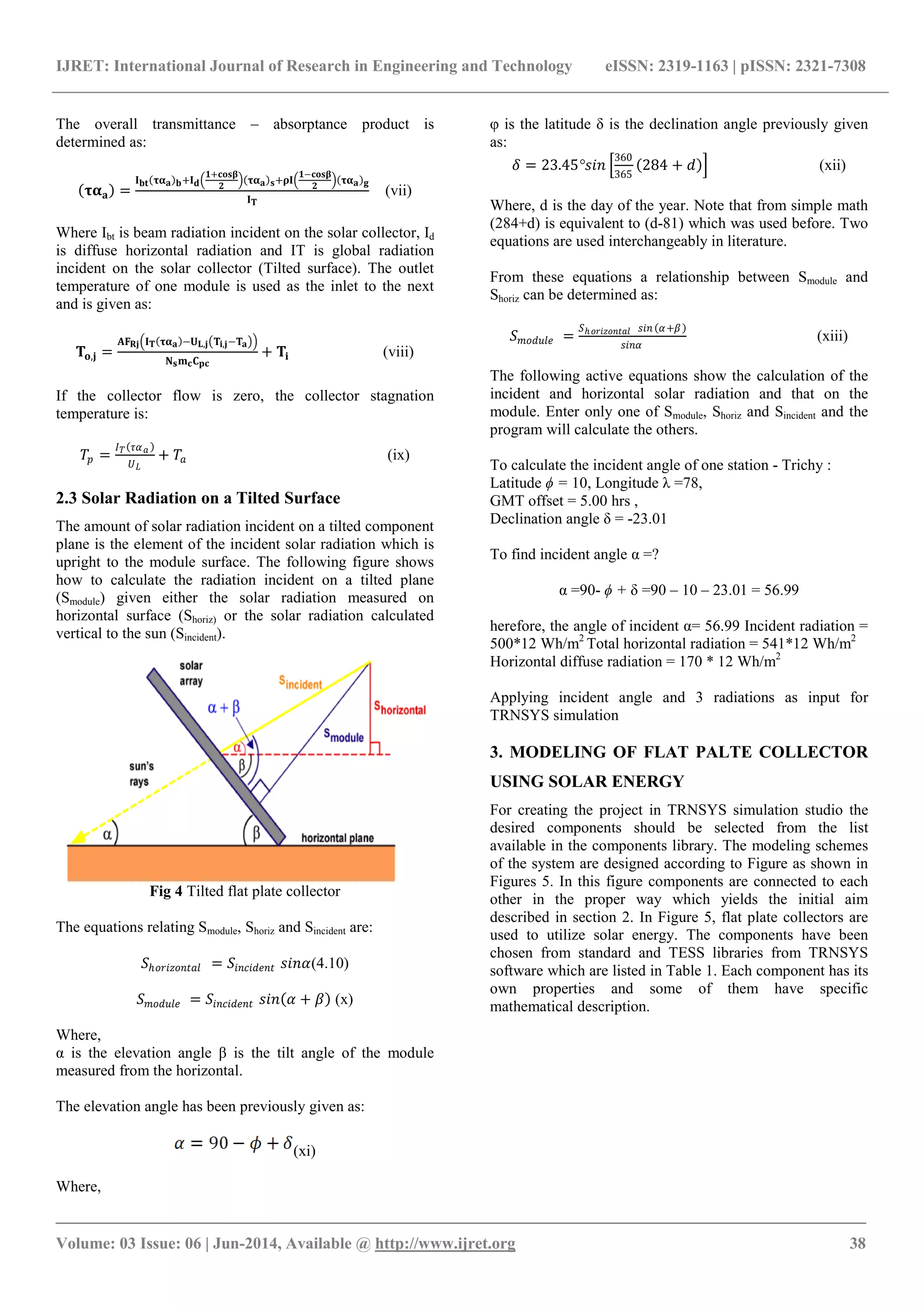
1.3 Flat Plate Collectors
The flat plate collectors ar5e most commonly used in the
domestic hot water system on the roof tops. They consist of
a black coated absorber, a transparent acrylic cover that
reduces heat losses, a heat transfer fluid to extract heat from
the absorber, and a heat insulating packing. In water heat
panels, fluid is usually circulated through tubes to transfer
heat from the absorber to an insulated storage tank. This
may be achieved directly or through a heat exchanger.
Fig 1 Flat plate collectors
Hilmer et al. 1999 presented a method to calculate
numerically the solar collector with varying parameters [1].
Zuefa and Magiera 2001 published an experimental study in
the more uniform for the flow distribution, the higher the
collector efficiency. But uniform flow distributions are not
possible in solar collectors [2]. Fan et al. 2007 investigated
both experimentally and theoretically the finned tube flat
plate collector. They analyzed numerically by CFD and got
results which oriented with experiment results [3].
Augustus and Kumar 2006 developed mathematical model
for an unglazed perforated flat plate collector. They
developed an empirical relation for various components.
They proved the improved results of absorptivity, heat
transfer and air flow rate[4]. Molero et al. 2009 presented a](https://image.slidesharecdn.com/simulationofsolarintensityinperformanceofflat-140820042920-phpapp01/75/Simulation-of-solar-intensity-in-performance-of-flat-1-2048.jpg)
![IJRET: International Journal of Research in Engineering and Technology eISSN: 2319-1163 | pISSN: 2321-7308
_______________________________________________________________________________________
Volume: 03 Issue: 06 | Jun-2014, Available @ http://www.ijret.org 37
3-D numerical model for flat-plate solar collector
considering the transient conditions like flow characteristics.
But this un-uniform flow does not make huge effect in
collector efficiency. When the dimensions of the tube
increases with the flow increases with due change in
collector efficiency [5].
Anderson et al 2009[6] examined the performance by
changing the colours of solar collector. Based on the
transmittance-absorptance result of various colored
collectors the hypothetical performances of these collectors
were calculated using the Hottel-Whillier-Bliss 1-D steady-
state model given by Duffie and Beckmann 2006[7]. By
these experiments they concluded that the colour of the
collector plays a major role in thermal efficiencies of the
collectors.
Fig 2 Irradiation data of Flat plate collector
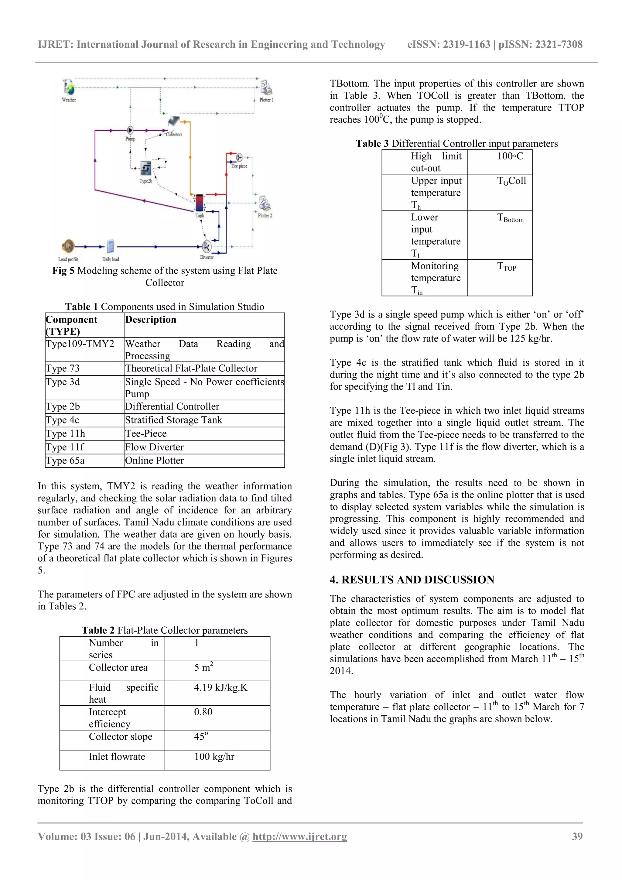
1.4 Domestic Hot Water System (DHWS)
Fig 3 Schematic diagram of solar water heating system
The various day of the year weather data’s are absorbed by
the solar collector (A). Flat Plate Collector (FPC) were
connected in array in parallel arrangements. To improve the
hot water system performance and to study the stratification
of the storage tank a hot water storage tank (B) was used
here. As a outcome, a temperature variation between the top
and the bottom parts of the tank arises the density variation
between top and bottom. The high density fluid come to the
bottom side and the low density fluid to the top of the tank.
An on/off differential controller (C) is use to control the
temperature variation between TOColl and TBottom. Controlling
the temperature can have a significant effect on the final
result. In this case, the TOColl is adjusted as the Upper input
temperature Th, TBottom is adjusted as Lower input
temperature Tl and TTOP is adjusted as Monitoring
temperature Tin. The temperature data’s from hot and cold
water side sends the appropriate signal to the pump
according to the dead bands. There is a high limit cut out
temperature that can be defined as desired.
2. SYSTEM AND MATHEMATICAL MODEL
2.1 Solar Collectors
The flat plate collector (quadratic efficiency) Type 1b is
selected from TRNSYS component libraries. This
component models the thermal performance of a flat- plate
solar collector. The number of modules in series and the
characteristics of each module determine the thermal
performance of the collector array. Equation 1 gives the
solar collector thermal efficiency.
ηcol = m .cp (To-col - Ti-col) / Acol It (i)
TRNSYS models of solar collectors have different types of
functions named parameters, inputs and outputs. A
parameter value function is specifically related to the
manufacturer (Thermo Dynamics Ltd.). These values need
to be input according to manufacturer specifications. An
input value function has a value that depends upon the test
conditions, such as collector slope, orientation, etc. Some
inputs and all outputs have a ‘linked’ value, which means
that this function has values, which are linked to other
components and will be determined by the real time flow.
2.2Theoretical Flat-Plate Collector
The energy compilation of each component in an array of Ns
modules in series is modeled according to the Hottel-
Whillier equation such that (j is the module number):
Qu =
A
Ns
FRj
Ns
j=1 IT ταa − ULj Tij − Ta (ii)
Where FR,j can be explained as follows:
𝐹𝑅𝑗 =
𝑁 𝑠 𝑚 𝑐 𝐶 𝑝𝑐
𝐴𝑈 𝐿𝑗
1 − 𝑒𝑥𝑝 −
𝐹𝑈 𝐿𝑗 𝐴
𝑁 𝑠 𝑚 𝑐 𝐶 𝑝𝑐
(iii)
The following expression, developed by Klein, is used to
approximate UL,j(in KJ/h-m2-K). Equation (iii) is described
as:
𝐔 𝐋𝐣 =
𝟑.𝟔
𝐍 𝐆
𝐂
𝐓 𝐩𝐣
𝐓 𝐚𝐯𝐣−𝐓 𝐚
𝐍 𝐆+𝐟
.𝟑𝟑
+
𝟏
𝐡 𝐰
+
𝟑.𝟔𝛔 𝐓 𝐚𝐯𝐣
𝟐
+𝐓 𝐚
𝟐 𝐓 𝐚𝐯𝐣+𝐓 𝐚
𝟏
𝛆 𝐩+.𝟎𝟓𝐍 𝐆 𝟏−𝛆 𝐩
+
𝟐𝐍 𝐆+𝐟−𝟏
𝛆 𝐠
−𝐍 𝐆
+ 𝐔 𝐛𝐞(iv)
And
Hw=5.7 +3.8 W (W/m2 – K) (v)
f = (1-0.04 hw + 0.0005 hw2) (1+0.091 NG) (vi)](https://image.slidesharecdn.com/simulationofsolarintensityinperformanceofflat-140820042920-phpapp01/75/Simulation-of-solar-intensity-in-performance-of-flat-2-2048.jpg)
![IJRET: International Journal of Research in Engineering and Technology eISSN: 2319-1163 | pISSN: 2321-7308
_______________________________________________________________________________________
Volume: 03 Issue: 06 | Jun-2014, Available @ http://www.ijret.org 41
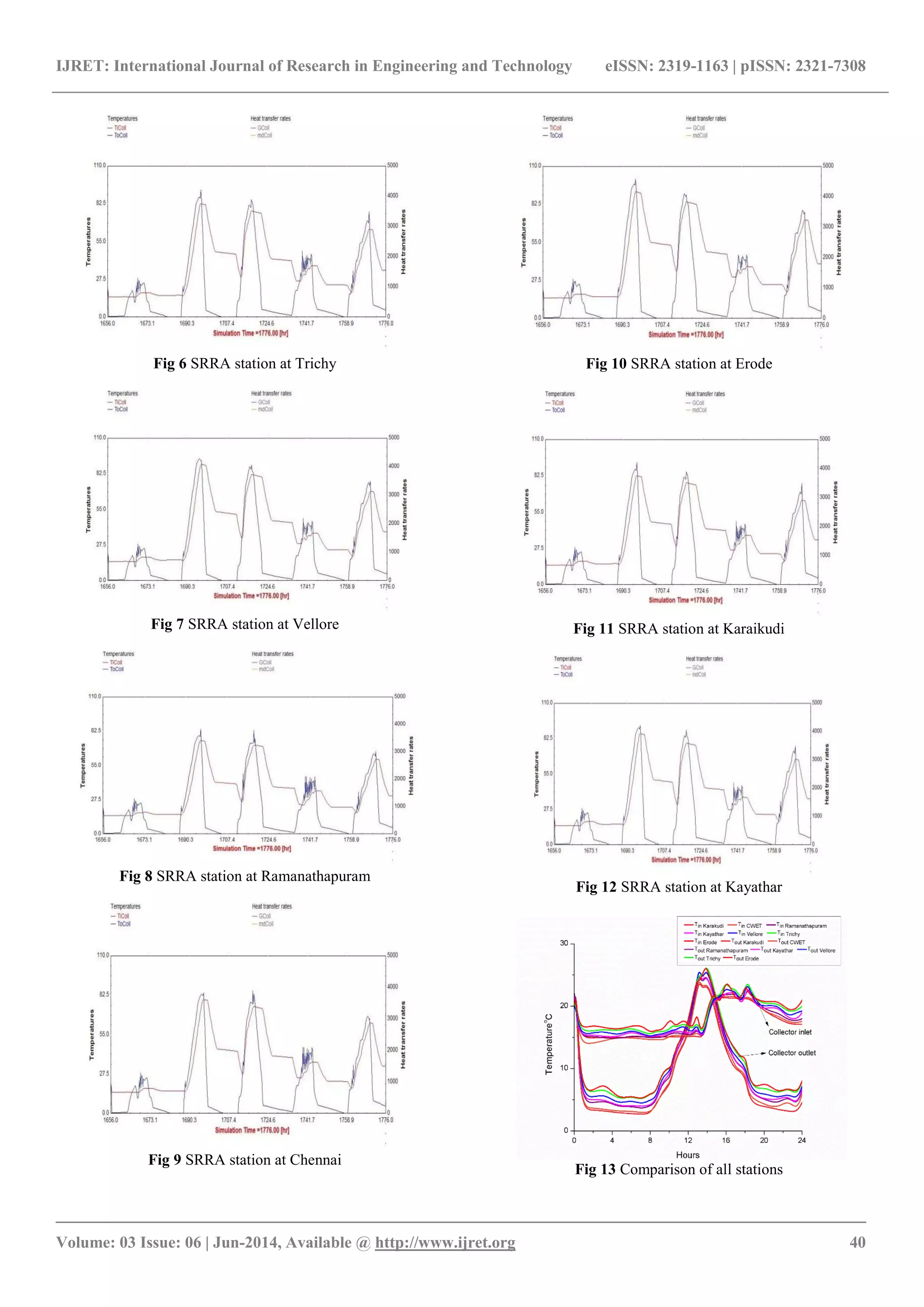
5. CONCLUSIONS
Solar energy is important to meet the increasing demand of
energy required for daily domestic needs. Therefore, an
extensive research has been done to model the flat plate
collector and predict the performance of different locations
in Tamil Nadu. The aim of this study is to simulate the
maximum use of solar radiation in 7 geographic locations in
Tamil Nadu using TRNSYS software. The hourly
investigations are performed for five days from 11th
– 15th
March and radiations are taken for the various locations.
The results were simulated and the graphs were compared. It
was observed that Erode had the maximum output
performance using flat plate collector which can be used to
replace the energy consumption of non-renewable resources.
ACKNOWLEDGMENTS
This work was supported by Center for Wind Energy
Technology (CWET), Chennai for data Collection.
REFERENCES
[1]. f. Hilmer, k.Vajen,a.Ratka, h.Ackermann, w.Fuhs,
o.Melsheimer, Numerical solution and validation of a
dynamic model of solar collectors working with varying
fluid flow rate, solarenergy,volume65,issue5,1999, 305-321.
[2]. Zueva G. and Magiera J., 2001, Mathematical model of
heat transfer in solar collector and its experimental
validation, Theoretical Foundations of Chemical
Engineering, 35, 6, 604-608.
[3]. Fan J., Shah L., and Furbo S., 2007, Flow distribution in
a solar collector panel with horizontally inclined absorber
strips, Solar Energy, 81, 1501-1511.
[4]. Augustus M. and Kumar S., 2007, Mathematical
modeling and thermal performance analysis of unglazed
transpired solar collectors, Solar Energy, 81, 62-75.
[5]. Molero Villar N., Cejudo Lopez J., and Dominguez
Munoz F., 2009, Numerical 3-D heat flux simulations on
flat plate solar collectors, 83, 1086-1092.
[6]. Anderson T., Duke M., and Carson J., 2010, The effect
of color on the thermal performance of building integrated
solar collectors, Solar Energy Materials & solar cells, 94,
350-354.
[7]. Duffie J. and Beckmann W., 1991, Solar engineering of
thermal processes, 2nd edition (Wiley Interscience, New
York).](https://image.slidesharecdn.com/simulationofsolarintensityinperformanceofflat-140820042920-phpapp01/75/Simulation-of-solar-intensity-in-performance-of-flat-6-2048.jpg)

The document discusses the simulation of solar intensity and the performance of flat plate collectors in Tamil Nadu, focusing on the use of TRNSYS software for modeling. It provides insights into the efficiency of solar collectors at different geographic locations and emphasizes the importance of solar energy as a renewable resource. The study concludes that areas like Erode exhibit optimal output performance for domestic energy needs through solar energy utilization.