Download as PPS, PPTX


![2. FLAT-PLATE COLLECTORS
A flat plate collector is basicly a black surface that is place d at
a convenient path of the sun.And a typical flat plate collector
is a metal box with a glass or plastic cover (called glazing) on
top and a dark-colored absorber plate on the bottom. The sides
and bottom of the collector are usually insulated to minimize
heat loss.[2]
Figure 2.1 gives examples of flat-plate collectors
Figure 2.1 Flat-plate collectors[3].](https://image.slidesharecdn.com/6564845-flat-plate-collector-130208122350-phpapp01/85/6564845-flat-plate-collector-5-320.jpg)
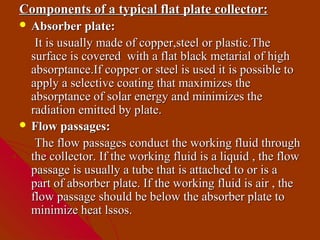
![ Cover plate:
To reduce convective and radiative heat losses from
the absorber , one or two transparent covers are
generally placed above the absorber plate.They
usually be made from glass or plastic.
Insulation:
These are some metarials such as fiberglass and they
are placed at the back and sides of the collector to
rduce heat losses.
Enclosure:
A box that the collector is enclosed in holds the
componrnts together, protect them from weather,
facilitates installation of the collector on a roof or
appropriate frame [1].](https://image.slidesharecdn.com/6564845-flat-plate-collector-130208122350-phpapp01/85/6564845-flat-plate-collector-7-320.jpg)
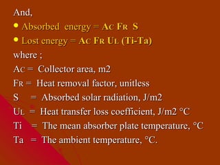
![Here in figure 2.2 we can see components of flat plate
collectors.
Figure 2.2 Cross section of a basic flat-plate solar collector [4].](https://image.slidesharecdn.com/6564845-flat-plate-collector-130208122350-phpapp01/85/6564845-flat-plate-collector-8-320.jpg)
![A. Absorber plate & Flow passages
Copper,which has high conductivity and is corrosion-resistant,
is the material for absorber plates, but because copper is
expensive, steel is also widely used. For a copper plate 0.05
cm thick with 1.25-cm tubes spaced 15 cm apart in good
thermal contact with the copper, the fin efficiency is better
than 97 percent.
The surface of the absorber plate determines how much of the
incident solar radiation is absorbed and how much is emitted
at a given temperature. Flat black paint which is widely used
as a coating has an absorptance of about 95 percent for
incident shortwave solar radiation. It is durable and easy to
apply [1].](https://image.slidesharecdn.com/6564845-flat-plate-collector-130208122350-phpapp01/85/6564845-flat-plate-collector-9-320.jpg)
![Here a table about matters that absorber plate may be made
from
Material Absorptance Emittance Break down Comments
temparature
(α) ( ε)
(°C)
Black silicon 0.86-0.94 0.83-0.89 350 Slicone
paint binder
Black silicon 0.9 0.5 Stable at
paint high
temperature
Black copper 0.85-0.9 0.08-0.12 450 Patinates
over copper with moisture
Black 0.92-0.94 0.07-0.12 450 Stable at high
chorome temperatures
over nickel
Table 2.1 Characteristics of absorptive coatings [1].](https://image.slidesharecdn.com/6564845-flat-plate-collector-130208122350-phpapp01/85/6564845-flat-plate-collector-10-320.jpg)
![Here in figure 2.3 we can see absorber plate and flow
passages
Figure 2.3 Cross section of a absorber plate&flow passages of a flat
plate collector [4].](https://image.slidesharecdn.com/6564845-flat-plate-collector-130208122350-phpapp01/85/6564845-flat-plate-collector-11-320.jpg)
![B. Cover plates
A cover plate for a collector should have a high transmittance
for solar radiation and should not detoriate with time. The
material most commonly used is glass. A 0.32-cm thick sheet
of window glass ( iron content, 0.12 percent ) transmits 85
percent of solar energy at normal incidence. And all glass is
practically opaque to long-wavelength radiation emitted by the
absorber plate.
Some plastic materials can be used for collector glazing.They
are cheaper and lighter than glass and, because they can be
used in very thin sheets, they often have higher transmittance.
However, they are not as durable as glass and they often
degrade with exposure to ultraviolet radiation or high
temperatures [1].](https://image.slidesharecdn.com/6564845-flat-plate-collector-130208122350-phpapp01/85/6564845-flat-plate-collector-12-320.jpg)
![Here a table about matters that cover plate may be made from
Test Polyvinly Polyethylene Polycarbonate Fiberglass
terephthatalet rein forced
floride or polyster plastics
Solar
Transmission, %
92-94 85 82-89 77-90
Maximu
operating
110 100 120-135 95
temperature ° C
Thermal
Expansion
43 27 68 32-40
Coefficient
Thickness, 0.1 0.025 3.2 1.0
mm
Length of In 5 years 95%
retains
4 7-20
life, years
Table 2.2 Charactericts of cover plate materials [1].](https://image.slidesharecdn.com/6564845-flat-plate-collector-130208122350-phpapp01/85/6564845-flat-plate-collector-13-320.jpg)
![Here in figure 2.4 we can see cover part.
Figure 2.4 Cross section of a cover part of a flat-plate collector [4].](https://image.slidesharecdn.com/6564845-flat-plate-collector-130208122350-phpapp01/85/6564845-flat-plate-collector-14-320.jpg)
![C. Enclosure / Insulation
The collector enclosure is usually made from steel, aliminium
or fiber glass.And order to prevent heat from escaping through
the back of the collector,a layer of insulation is placed behind
the absorber plate [1].
Material Density Kg/m3 Thermal Temperature
conductivity at limits °C
95 °C (W/mK)
Fiber glass with 11 0.059 175
organic binder
“ 16 0.050 175
“ 24 0.045 175
“ 48 0.43 175
Table 2.3 Characteristics of insulation materials [1].](https://image.slidesharecdn.com/6564845-flat-plate-collector-130208122350-phpapp01/85/6564845-flat-plate-collector-15-320.jpg)
![Here in figure 2.5 we can see insulation part.
Figure 2.5 Cross Section of an Insulation Part of a Flat-Plate Collector
[4].](https://image.slidesharecdn.com/6564845-flat-plate-collector-130208122350-phpapp01/85/6564845-flat-plate-collector-16-320.jpg)

![A. Flat-plate collectors facing south
at fixed tilt:
To optimize performance in the winter, the collector can be
tilted 15 ° greater than the latitude; to optimize performance in
the summer, the collector can be tilted 15 ° less than the
latitude [5]. Figure 3.1 show how the collector is tilted.
Figure 3.1 Flat-plate collector at fixed tilt [5].](https://image.slidesharecdn.com/6564845-flat-plate-collector-130208122350-phpapp01/85/6564845-flat-plate-collector-18-320.jpg)
![B. One-axis tracking flat-plate collectors
with axis oriented north-south:
These trackers pivot on their single axis to track the sun, facing
east in the morning and west in the afternoon as shown in
figure 3.2.
Figure 3.2 Flat-plate collector one axis tracking[5].](https://image.slidesharecdn.com/6564845-flat-plate-collector-130208122350-phpapp01/85/6564845-flat-plate-collector-19-320.jpg)
![C. Two-axis tracking flat-plate
collectors:
Tracking the sun in both azimuth and elevation, these
collectors keep the sun's rays normal to the collector surface as
shown in figure 3.3.
Figure 3.3 Flat-plate collector with two axis tracking[5].](https://image.slidesharecdn.com/6564845-flat-plate-collector-130208122350-phpapp01/85/6564845-flat-plate-collector-20-320.jpg)
![4.COLLECTOR PERFORMANCE
The thermal performance of a collector can be
calculated from a first-law energy balance. according
to the first law of thermodynamics, for a simple flat-
plate collector an instantaneous steady-state energy
balance is[1] :
Useful energy = energy absorbed – heat loss to
gain (Qu) by the collector surroundings](https://image.slidesharecdn.com/6564845-flat-plate-collector-130208122350-phpapp01/85/6564845-flat-plate-collector-21-320.jpg)
![So;
QU = AC FR S - AC FR UL (Ti-Ta)
Equation 4.1 Useful gain enerrgy equation[6].](https://image.slidesharecdn.com/6564845-flat-plate-collector-130208122350-phpapp01/85/6564845-flat-plate-collector-23-320.jpg)
![Equation 4.1 is an extremely useful equation and
applies to essentialy all flat-plate collectors.
And to improve theperformance of solar collector it is
necesssary either to reduce the overall energy loss
coefficient or reduce area from which energy is lost.
That is; the maximum possible useful energy gain (heat
transfer) in a solar collector occurs when the whole
collector is at the inlet fluid temperature; heat losses to
the surroundings are then at a minimum [1,6].](https://image.slidesharecdn.com/6564845-flat-plate-collector-130208122350-phpapp01/85/6564845-flat-plate-collector-24-320.jpg)
![A. Absorbed radiation (S):
In equation 4.1 S is absorbed radiation and it is equal to:
1 + cos β 1 − cos β
S = I b Rb (τα ) b + I d (τα ) d + ρ g ( I b + I d )(τα ) g
2 2
Equation 4.2 Absorbed solar radiation[6].
In equation 4.2 ; (1 +cos β / 2), (1 −cos β / 2) are
the view factors from the collector to the sky and
from the collector to the ground, respectively.
The subscripts b,d, and g represent beam,
diffuse, and ground , respectively. ( α is
τ )
transmittance and absorptance product.Rb is the
ratio of beam radiation on the tilted surface to that on a
horizantal surface at any time[6].](https://image.slidesharecdn.com/6564845-flat-plate-collector-130208122350-phpapp01/85/6564845-flat-plate-collector-25-320.jpg)
![B. Collector heat removal factor (F R):
In equation 4.1 FR is collector heat removal factor ; a quantity that relates the
actual useful energy gain of a collector to the useful gain if the whole collector
surfaces were at the fluid inlet temperature[6]. And it is given by equation 4.3.
Equation 4.3 the collector heat removal factor FR [6].
Where;
m’ = Fluid mass flow rate, kg/s
Cp = Fluid specific heat, J/kg °C
The quantitiy FR is equavialent to the effectiveness of a
conventional heat exchange, which is defined as the ratio of the actual
heat transfer to the maximum possible heat transfer. The maximum
possible useful energy gain (heat transfer) in a solar collector occurs
when the all whole collector is at the inlet fluid temperature; heat
losses to the surroudings are than at a minimum [6].](https://image.slidesharecdn.com/6564845-flat-plate-collector-130208122350-phpapp01/85/6564845-flat-plate-collector-26-320.jpg)
![C. Overall heat loss coefficient (U L):
In equation 4.1 UL is the collector overall loss
coefficient and it is equal to the sum of the top,
bottom,and edge loss coefficients [6]:
UL=Utop+Ubottom+Uedge,W/m²K
Equation 4.4 Overall loss coefficient UL [6].](https://image.slidesharecdn.com/6564845-flat-plate-collector-130208122350-phpapp01/85/6564845-flat-plate-collector-27-320.jpg)
![Energy diagram of typical flat flate collector is
shown in figure 5.1. % 92 of the total sunshine
reaches to the copper absorber.% 8 of the total
sunshine is reflected from glass.% 5 of the sunshine is
emitted from the panel, %12 is lost through
convection and conduction.
Figure 5.1 Energy diagram for typical flat plate collector [3]](https://image.slidesharecdn.com/6564845-flat-plate-collector-130208122350-phpapp01/85/6564845-flat-plate-collector-28-320.jpg)
![5. COLLECTOR EFFICIENCY
The basic method of measuring collector
performance is to expose the operating collector to
solar radiation and measure the fluid inlet and outlet
temperatures and the fluid flow rate.The useful gain is
[6];
QU = m′ C P (T0 − Ti )
Equation 5.1 Energy gained by liquid[6].
Where;
m’ = Fluid mass flow rate, kg/s
Cp = Fluid specific heat, J/kg°C](https://image.slidesharecdn.com/6564845-flat-plate-collector-130208122350-phpapp01/85/6564845-flat-plate-collector-29-320.jpg)
![The equation 5.1 which describes the thermal
performance of a collector operating under steady
conditions, can be rewritten [6];
Qu = Ac FR [ GT (τα ) − U L ( Ti − Ta ) ]
Equation 5.2 Useful gain enerrgy equation[6].
Where (τα ) is a transmittance-absorptance product
that is weighted according to the proportions of beam,
diffuse, and ground reflected radiation on the
collector [6].](https://image.slidesharecdn.com/6564845-flat-plate-collector-130208122350-phpapp01/85/6564845-flat-plate-collector-30-320.jpg)
![And finally; instantaneous efficiency
can be defined as [6]:
Qu FRU L ( Ti − Ta )
ni = = FR (τα ) −
Ac GT GT
That is;
m' C p ( T0 − Ti )
ni =
Ac GT](https://image.slidesharecdn.com/6564845-flat-plate-collector-130208122350-phpapp01/85/6564845-flat-plate-collector-31-320.jpg)

![A) Domestic applications
Flate plate collectors mainly used in residential buildings where
the demand for hot water has a large impact on energy bills. This
generally means a situation with a large family, or a situation in
which the hot water demand is excessive due to frequent laundry
washing [2].
For instance, a family of 4 members consumes on an average
100 litre of hot water a day at 60 ˚C. Hot water of 100 litre
capacity at 60 ˚C approximate can be delivered by a single
collector system of 2 m² area. The solar water heating systems
are
generally provided with auxiliary backup in the insulated hot
storage tank for the rainy and heavily overcast cloudy days [7].](https://image.slidesharecdn.com/6564845-flat-plate-collector-130208122350-phpapp01/85/6564845-flat-plate-collector-33-320.jpg)
![Here we can see solar flat-plate collectors used for
heating buildings.
Figure 6.1 Flat plate collectors used for heating buildings [8].](https://image.slidesharecdn.com/6564845-flat-plate-collector-130208122350-phpapp01/85/6564845-flat-plate-collector-34-320.jpg)
![B) Commercial applications
Commercial applications include laundromats, car washes,
military laundry facilities and eating establishments. Solar water
heating systems are most likely to be cost effective for facilities
with water heating systems that are expensive to operate, or with
operations such as laundries or kitchens that require large
quantities of hot water.
And unglazed liquid collectors are commonly used to heat
water for swimming pools. Because these collectors need not
withstand high temperatures, they can use lessexpensive
materials such as plastic or rubber. They also do not require
freeze-proofing because swimming pools are generally used only
in warm weather or can be drained easily during cold weather
[2].](https://image.slidesharecdn.com/6564845-flat-plate-collector-130208122350-phpapp01/85/6564845-flat-plate-collector-35-320.jpg)
![Here we can see solar flat-plate collectors used for
heating swimming pools.
Figure 6.2 Flat-plate collectors used for heating swimming pools [9].](https://image.slidesharecdn.com/6564845-flat-plate-collector-130208122350-phpapp01/85/6564845-flat-plate-collector-36-320.jpg)

![REFERENCES
[1] Jan F. Kreider, Charles J. Hoogendoorn,
Frank Kreith “ Solar Design “ Hemisphere
Publishing Corporation, (1989), pp. 44-55.
[2] http://www.flasolar.com
[3] http://www.solarnetrix.com
[4] http://www.solstice.crest.org
[5] http://www.rredc.nrel.gov
[6] Duffie, J. A. and Beckman, W. A. , 1991. Solar
Engineering of Thermal Processes , John Wiley and
Sons Inc., New York, pp.250-290 .
[7] http://www.iredaltd.com
[8] http://www.ips-solar.com
[9] http://www.northeastpoolstore.com](https://image.slidesharecdn.com/6564845-flat-plate-collector-130208122350-phpapp01/85/6564845-flat-plate-collector-38-320.jpg)

This document discusses flat-plate solar collectors. It describes the key components of flat-plate collectors including the absorber plate, flow passages, cover plates, enclosure and insulation. Absorber plates are typically made of copper or steel while cover plates are usually glass or plastic. Insulation such as fiberglass is used to limit heat loss. Flat-plate collectors can be oriented fixed, or use one-axis or two-axis tracking to follow the sun for improved performance. Collector performance depends on absorbed radiation, heat removal factor and heat loss coefficient. Applications include domestic hot water and space heating.


