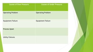
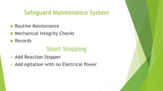
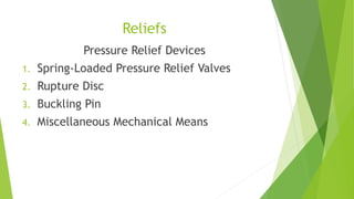
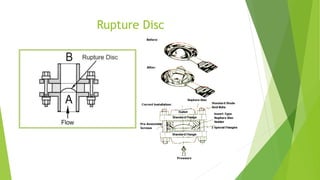
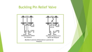
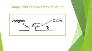
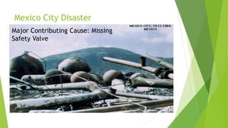
Pressure Safety Devices 
“Grace Under Pressure” 
-Earnest Hemingway 
Faizan Ahmad 
ICET, Punjab University 
Lahore, Pakistan
Pressure Terminologies 
 Accumulation 
 Design Pressure 
 Set Pressure 
 Operating Pressure 
 Overpressure 
 Underpressure 
 Popping Pressure
Causes of Over Pressure Causes of Under Pressure 
Operating Problem Operating Problem 
Equipment Failure Equipment Failure 
Process Upset 
Utility Failures
Safeguards 
 Safety Interlocks 
 Safeguard Maintenance Systems 
 Short Stopping
Safety Interlocks 
 Agitator not working 
 Abnormal Temperature 
 Abnormal Pressure 
 Abnormal Heat Balance 
For all these Abnormalities: Stop Feed and Add 
full Cooling
Safeguard Maintenance System 
 Routine Maintenance 
 Mechanical Integrity Checks 
 Records 
Short Stopping 
 Add Reaction Stopper 
 Add Agitation with no Electrical Power
Reliefs 
Pressure Relief Devices 
1. Spring-Loaded Pressure Relief Valves 
2. Rupture Disc 
3. Buckling Pin 
4. Miscellaneous Mechanical Means
Spring Loaded Pressure Relief Valve
Rupture Disc
Buckling Pin Relief Valve 
Closed Pressure below 
Set Pressure 
Full Open Pressure at or 
above Set Pressure 
(Buckles in precise milliseconds at a precise set 
Pressure)
Simple Mechanical Pressure Relief
Other Types of Safety Valves 
 Balanced Bellows 
 Pilot Operated
Balanced Bellows Safety Valve
Pilot-Operated Safety Valve
When to Use Spring-Operated Safety 
Valve 
Spring-Operated Valve is used in following cases 
 Fluids above normal boiling point 
 Used where toxic fluids are handled 
 Return to normal conditions quickly 
Withstand process pressure changes, including vacuum 
 When fluid is of the Prime Importance
When to Use Rupture Disc/Safety pin 
Valve 
 Capital and maintenance savings 
 When fluid is not so expensive 
 For Benign Service (Non-toxic, Non-Hazardous) 
 Need for fast acting device 
 Potential for Relief valve plugging 
 Used for High Viscosity Liquids
When to Use Both Types 
 Need a positive Seal (Toxic Material, Material 
Balance Requirements) 
 Protect Safety Valve for Corrosion 
 System Contain Solids
Anything wrong 
here? 
Bellows plugged 
in spite of sign 
Failed 
Inspection 
Program 
Signs of 
Maintenance 
Issues
Anything wrong 
here? 
Anything wrong 
Discharges 
Pointing here? 
Down
Mexico City Disaster 
Major Contributing Cause: Missing 
Safety Valve
References: 
Mohammad A. Malek --- Pressure Relief 
Devices Chapters # 1, 3, 21 
Crowl, Louver --- Chemical Process Safety 
Chapter # 8
End of Presentation 
Thank-you

Pressure safety devices

  • 1.
    Pressure Safety Devices “Grace Under Pressure” -Earnest Hemingway Faizan Ahmad ICET, Punjab University Lahore, Pakistan
  • 2.
    Pressure Terminologies Accumulation  Design Pressure  Set Pressure  Operating Pressure  Overpressure  Underpressure  Popping Pressure
  • 3.
    Causes of OverPressure Causes of Under Pressure Operating Problem Operating Problem Equipment Failure Equipment Failure Process Upset Utility Failures
  • 4.
    Safeguards  SafetyInterlocks  Safeguard Maintenance Systems  Short Stopping
  • 5.
    Safety Interlocks Agitator not working  Abnormal Temperature  Abnormal Pressure  Abnormal Heat Balance For all these Abnormalities: Stop Feed and Add full Cooling
  • 6.
    Safeguard Maintenance System  Routine Maintenance  Mechanical Integrity Checks  Records Short Stopping  Add Reaction Stopper  Add Agitation with no Electrical Power
  • 7.
    Reliefs Pressure ReliefDevices 1. Spring-Loaded Pressure Relief Valves 2. Rupture Disc 3. Buckling Pin 4. Miscellaneous Mechanical Means
  • 8.
  • 9.
  • 10.
    Buckling Pin ReliefValve Closed Pressure below Set Pressure Full Open Pressure at or above Set Pressure (Buckles in precise milliseconds at a precise set Pressure)
  • 11.
  • 12.
    Other Types ofSafety Valves  Balanced Bellows  Pilot Operated
  • 13.
  • 14.
  • 15.
    When to UseSpring-Operated Safety Valve Spring-Operated Valve is used in following cases  Fluids above normal boiling point  Used where toxic fluids are handled  Return to normal conditions quickly Withstand process pressure changes, including vacuum  When fluid is of the Prime Importance
  • 16.
    When to UseRupture Disc/Safety pin Valve  Capital and maintenance savings  When fluid is not so expensive  For Benign Service (Non-toxic, Non-Hazardous)  Need for fast acting device  Potential for Relief valve plugging  Used for High Viscosity Liquids
  • 17.
    When to UseBoth Types  Need a positive Seal (Toxic Material, Material Balance Requirements)  Protect Safety Valve for Corrosion  System Contain Solids
  • 18.
    Anything wrong here? Bellows plugged in spite of sign Failed Inspection Program Signs of Maintenance Issues
  • 19.
    Anything wrong here? Anything wrong Discharges Pointing here? Down
  • 20.
    Mexico City Disaster Major Contributing Cause: Missing Safety Valve
  • 21.
    References: Mohammad A.Malek --- Pressure Relief Devices Chapters # 1, 3, 21 Crowl, Louver --- Chemical Process Safety Chapter # 8
  • 22.

Editor's Notes

  • #21 During the early morning of Monday, 19 November 1984, one of the largest disasters in industrial history occurred in the Mexico City Area, causing the greatest rescue effort to assist population in an emergency ever undertaken. The tragic catastrophe started in a large LPG (Liquid Petroleum Gas) storage and distribution center in San Juan Ixhuatepec, 20 km north of Mexico City. The facilities, owned by the Pemex State Oil Company, consisted of six spherical storage tanks (four with a volume of 1600 m3 and two with a volume of 2400 m3) and 48 horizontal cylindrical bullet tanks of different sizes. At the time of the disaster the storage tanks contained 11,000 m3 of a mixture of propane and butane. The inhabitants of San Juan Ixhuatepec numbered about 40,000, and a further 60,000 lived in the hills surrounding the village. The majority were poor country people living in one-story houses constructed of concrete pillars filled in with bricks and with roofs of iron sheets. The disaster started due to LPG leakage, probably a pipe leakage or rupture due to excess pressure. A vapour cloud built up and was slowly moved by the north-east wind towards the ground-placed flare pit located in the western part of the plant. The vapour cloud was ignited around 5:40 a.m. and was followed by an extensive fire at the plant area. The first explosion was registered on the seismograph at the University of Mexico at 05 h 44 min 52 s and was followed by a dozen explosions within the next hour, some of them of BLEVE type (Boiling Liquid Expanding Vapour Explosion) due to rupture of one or more storage tanks. Two of the explosions had an intensity of 0.5 on the Richter scale. Unburned and burning gas entered the houses south of the plant area and set fire to everything. Blast waves from the explosions not only destroyed a number of houses but also shifted several cylindrical tanks from their supports and added more gas to the fire. The smaller spheres and some of the cylinders exploded and fragments and even whole cylinders weighing around 30 tons, were scattered over distances ranging from a few to up to 1200 m.