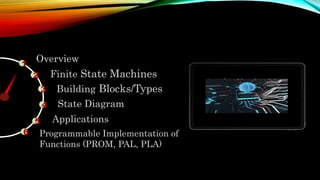
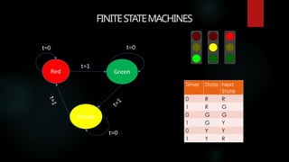
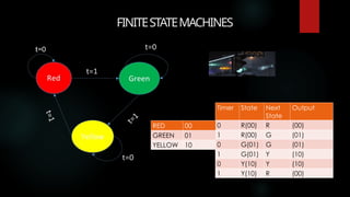
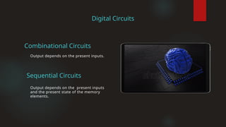
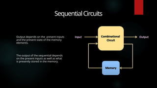
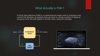
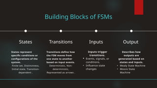
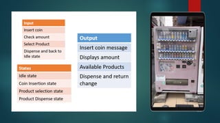
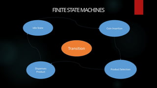
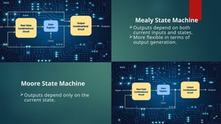
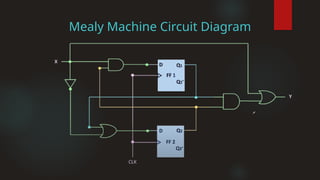
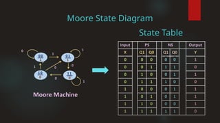
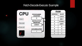
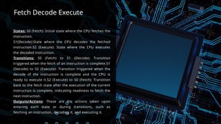
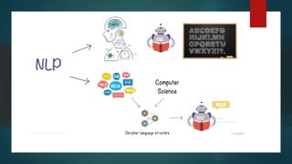
MEET
Gohar Abbass
Muhammad Haris
Muhammad Bilal
Abdul Rehman
23021519-
116
23021519-084
23021519-092
23021519-147
Muhammad Bilal
TEAM
OUR
PRESENTED TO
Ms. Sehar Aftab
BSCS23(II-A-Mor)
TOPIC
FINITE STATE MACHINES
1
Overview
2
3
Finite State Machines
Building Blocks/Types
4 State Diagram
5 Applications
Programmable Implementation of
Functions (PROM, PAL, PLA)
6
FINITESTATEMACHINES
FINITESTATEMACHINES
Timer State Next
State
0 R R
1 R G
0 G G
1 G Y
0 Y Y
1 Y R
t=0
FINITESTATEMACHINES
Timer State Next
State
Output
0 R(00) R (00)
1 R(00) G (01)
0 G(01) G (01)
1 G(01) Y (10)
0 Y(10) Y (10)
1 Y(10) R (00)
RED 00
GREEN 01
YELLOW 10
t=0
FINITE STATE
MACHINES
Finite State Machines (FSMs) play a crucial
role in understanding decision-making
logic and controlling digital systems.
In an FSM, the outputs and the next state
depend on the present state and the input
function. These state machines are
essential for designing sequential circuits
and modeling behavior in digital systems.
Digital
Logic
Design
Digital Circuits
Output depends on the present inputs
and the present state of the memory
elements.
Output depends on the present inputs.
Sequential Circuits
Combinational Circuits
SequentialCircuits
Output depends on the present inputs
and the present state of the memory
elements.
The output of the sequential depends
on the present inputs as well as what
is presently stored in the memory.
SequentialCircuits
Consider the Example of Changing
Channels on the Television using the
next channel button.
In the channel changing process the
output of the next channel depends
on the past channel.
For example, channel 2 will come after
1, channel three will come after 2.
Latches Flip-Flops
1 2
SequentialCircuits
Memory Elements
Level Trigger Edge Trigger
What Actually is FSM ?
A Finite State Machine (FSM) is a mathematical model used to represent and
control the behavior of systems that can exist in a finite number of states at
any given time. We will explain it further with a daily life example.
Building Blocks of FSMs
States represent
specific conditions or
configurations of the
system.
Finite set, Distinctness,
Initial state, Transition-
dependent .
States
Transitions define how
the FSM moves from
one state to another
based on input events.
Deterministic, Non-
deterministic,
Represented as arrows .
Transitions
Inputs trigger
transitions.
 Events, signals, or
conditions.
• Influence state
changes
Inputs
Describes how
outputs are
generated based on
states and inputs.
• Mealy State Machine
• Moore State
Machine
Output
FINITESTATEMACHINES
Moore State Machine
Mealy State Machine
Outputs depend on both
current inputs and states.
More flexible in terms of
output generation.
Outputs depend only on the
current state.
Mealy Machine Circuit Diagram
Moore Machine Circuit Diagram
REPRESENTATION
OF BEHAVIOUR
R P A S U M M E R 2 0 2 0
 State Transition Diagram:
 Pictorial
 State Table
 Tabular
 State Equations
 Algebraic
Here we only discuss State Transition
Diagram.
• Each Possible Output State is represented as a
Circle.
• Transitions from one state to another is
represented by an arrow.
So, that is how the State Diagram represents the behavior of
the finite state machines or any sequential circuit in a pictorial
way.
• The Value on the arrow indicates the input which
lead to the state transition.
STATE TRANSITION
DIAGRAM
• The value next to the input represents the output
for that input.
Mealy State Diagram
State Table
Moore State Diagram
State Table
Fetch-Decode-Execute Example
1
Fetch Decode Execute
States: S0 (Fetch): Initial state where the CPU fetches the
instruction.
S1(Decode):State where the CPU decodes the fetched
instruction.S2 (Execute): State where the CPU executes
the decoded instruction.
Transitions: S0 (Fetch) to S1 (Decode): Transition
triggered when the fetch of an instruction is complete.S1
(Decode) to S2 (Execute): Transition triggered when the
decode of the instruction is complete and the CPU is
ready to execute it.S2 (Execute) to S0 (Fetch): Transition
back to the fetch state after the execution of the current
instruction is complete, indicating readiness to fetch the
next instruction.
Outputs/Actions: These are the actions taken upon
entering each state or during transitions, such as
fetching an instruction, decoding it, and executing it.
Role of FSMs in CPU Design
Instruction Decoding:
FSMs help decode instructions fetched from memory. They
determine which operation (e.g., addition, subtraction, load,
store) the CPU should perform based on the opcode.
Control Signals:
FSMs generate control signals that activate specific
components (e.g., ALU, registers, memory) within the CPU.
These signals coordinate the execution of instructions.
State Transitions:
FSMs transition between states (e.g., fetch, decode, execute)
as the CPU progresses through the instruction cycle. Each state
corresponds to a specific phase of instruction processing.
TVSystemExample
Imagine you’re using a TV remote to change channels. The TV system
can be modeled as an FSM. Let’s break it down:
States
Off: The TV is turned off.
On: The TV is powered on.
Channel 1, Channel 2, …, Channel N: Different TV channels.
Transitions
When you press the power button, the system transitions
from Off to On.
When you press the channel up or down button, the system
transitions from one channel to another.
Actions:
Changing channels (switching from one state to another) is an
action.
Turning the TV on or off is also an action.
TVSystemExample
So, in this example:
The TV remote (and the TV itself) follows a set
of rules (states, transitions, and actions).
Each button press corresponds to a transition
between states (e.g., from Channel 1 to
Channel 2).
In summary, FSMs help us understand and
design systems with discrete and sequential
behavior, like changing TV channels! 📺
Natural Language
Processing FSM
States:
 Start
 Reading Noun
 Reading Verb
 End.
In natural language processing,
FSMs help parse sentences.
Programmable Logic
Devices
Design and working of
1-PROM
2-PLA
3-PAL
Programmable Logic
Array
@MuhammadBilal
THANKS
JAZAKALLAH!
Ms. Sehar Aftab
A special thank you to each of you for being part
of this journey. Your support fuels our passion for
creating impactful work..
From All of Group Members

Finite State Machines Digital Logic Design .pptx

  • 2.
    MEET Gohar Abbass Muhammad Haris MuhammadBilal Abdul Rehman 23021519- 116 23021519-084 23021519-092 23021519-147 Muhammad Bilal TEAM OUR PRESENTED TO Ms. Sehar Aftab BSCS23(II-A-Mor) TOPIC FINITE STATE MACHINES
  • 3.
    1 Overview 2 3 Finite State Machines BuildingBlocks/Types 4 State Diagram 5 Applications Programmable Implementation of Functions (PROM, PAL, PLA) 6
  • 4.
  • 5.
    FINITESTATEMACHINES Timer State Next State 0R R 1 R G 0 G G 1 G Y 0 Y Y 1 Y R t=0
  • 6.
    FINITESTATEMACHINES Timer State Next State Output 0R(00) R (00) 1 R(00) G (01) 0 G(01) G (01) 1 G(01) Y (10) 0 Y(10) Y (10) 1 Y(10) R (00) RED 00 GREEN 01 YELLOW 10 t=0
  • 7.
    FINITE STATE MACHINES Finite StateMachines (FSMs) play a crucial role in understanding decision-making logic and controlling digital systems. In an FSM, the outputs and the next state depend on the present state and the input function. These state machines are essential for designing sequential circuits and modeling behavior in digital systems. Digital Logic Design
  • 8.
    Digital Circuits Output dependson the present inputs and the present state of the memory elements. Output depends on the present inputs. Sequential Circuits Combinational Circuits
  • 9.
    SequentialCircuits Output depends onthe present inputs and the present state of the memory elements. The output of the sequential depends on the present inputs as well as what is presently stored in the memory.
  • 10.
    SequentialCircuits Consider the Exampleof Changing Channels on the Television using the next channel button. In the channel changing process the output of the next channel depends on the past channel. For example, channel 2 will come after 1, channel three will come after 2.
  • 11.
    Latches Flip-Flops 1 2 SequentialCircuits MemoryElements Level Trigger Edge Trigger
  • 12.
    What Actually isFSM ? A Finite State Machine (FSM) is a mathematical model used to represent and control the behavior of systems that can exist in a finite number of states at any given time. We will explain it further with a daily life example.
  • 13.
    Building Blocks ofFSMs States represent specific conditions or configurations of the system. Finite set, Distinctness, Initial state, Transition- dependent . States Transitions define how the FSM moves from one state to another based on input events. Deterministic, Non- deterministic, Represented as arrows . Transitions Inputs trigger transitions.  Events, signals, or conditions. • Influence state changes Inputs Describes how outputs are generated based on states and inputs. • Mealy State Machine • Moore State Machine Output
  • 15.
  • 16.
    Moore State Machine MealyState Machine Outputs depend on both current inputs and states. More flexible in terms of output generation. Outputs depend only on the current state.
  • 17.
  • 18.
  • 19.
    REPRESENTATION OF BEHAVIOUR R PA S U M M E R 2 0 2 0  State Transition Diagram:  Pictorial  State Table  Tabular  State Equations  Algebraic Here we only discuss State Transition Diagram.
  • 20.
    • Each PossibleOutput State is represented as a Circle. • Transitions from one state to another is represented by an arrow. So, that is how the State Diagram represents the behavior of the finite state machines or any sequential circuit in a pictorial way. • The Value on the arrow indicates the input which lead to the state transition. STATE TRANSITION DIAGRAM • The value next to the input represents the output for that input.
  • 21.
  • 22.
  • 23.
  • 24.
    Fetch Decode Execute States:S0 (Fetch): Initial state where the CPU fetches the instruction. S1(Decode):State where the CPU decodes the fetched instruction.S2 (Execute): State where the CPU executes the decoded instruction. Transitions: S0 (Fetch) to S1 (Decode): Transition triggered when the fetch of an instruction is complete.S1 (Decode) to S2 (Execute): Transition triggered when the decode of the instruction is complete and the CPU is ready to execute it.S2 (Execute) to S0 (Fetch): Transition back to the fetch state after the execution of the current instruction is complete, indicating readiness to fetch the next instruction. Outputs/Actions: These are the actions taken upon entering each state or during transitions, such as fetching an instruction, decoding it, and executing it.
  • 25.
    Role of FSMsin CPU Design Instruction Decoding: FSMs help decode instructions fetched from memory. They determine which operation (e.g., addition, subtraction, load, store) the CPU should perform based on the opcode. Control Signals: FSMs generate control signals that activate specific components (e.g., ALU, registers, memory) within the CPU. These signals coordinate the execution of instructions. State Transitions: FSMs transition between states (e.g., fetch, decode, execute) as the CPU progresses through the instruction cycle. Each state corresponds to a specific phase of instruction processing.
  • 26.
    TVSystemExample Imagine you’re usinga TV remote to change channels. The TV system can be modeled as an FSM. Let’s break it down: States Off: The TV is turned off. On: The TV is powered on. Channel 1, Channel 2, …, Channel N: Different TV channels. Transitions When you press the power button, the system transitions from Off to On. When you press the channel up or down button, the system transitions from one channel to another. Actions: Changing channels (switching from one state to another) is an action. Turning the TV on or off is also an action.
  • 27.
    TVSystemExample So, in thisexample: The TV remote (and the TV itself) follows a set of rules (states, transitions, and actions). Each button press corresponds to a transition between states (e.g., from Channel 1 to Channel 2). In summary, FSMs help us understand and design systems with discrete and sequential behavior, like changing TV channels! 📺
  • 28.
    Natural Language Processing FSM States: Start  Reading Noun  Reading Verb  End. In natural language processing, FSMs help parse sentences.
  • 30.
    Programmable Logic Devices Design andworking of 1-PROM 2-PLA 3-PAL
  • 35.
  • 37.
    @MuhammadBilal THANKS JAZAKALLAH! Ms. Sehar Aftab Aspecial thank you to each of you for being part of this journey. Your support fuels our passion for creating impactful work.. From All of Group Members