2
Required reading
• P.Chu, RTL Hardware Design using VHDL
Chapter 10, Finite State Machine:
Principle & Practice
3.
3
ECE 448 –FPGA and ASIC Design with VHDL
Datapath
vs.
Controller
4.
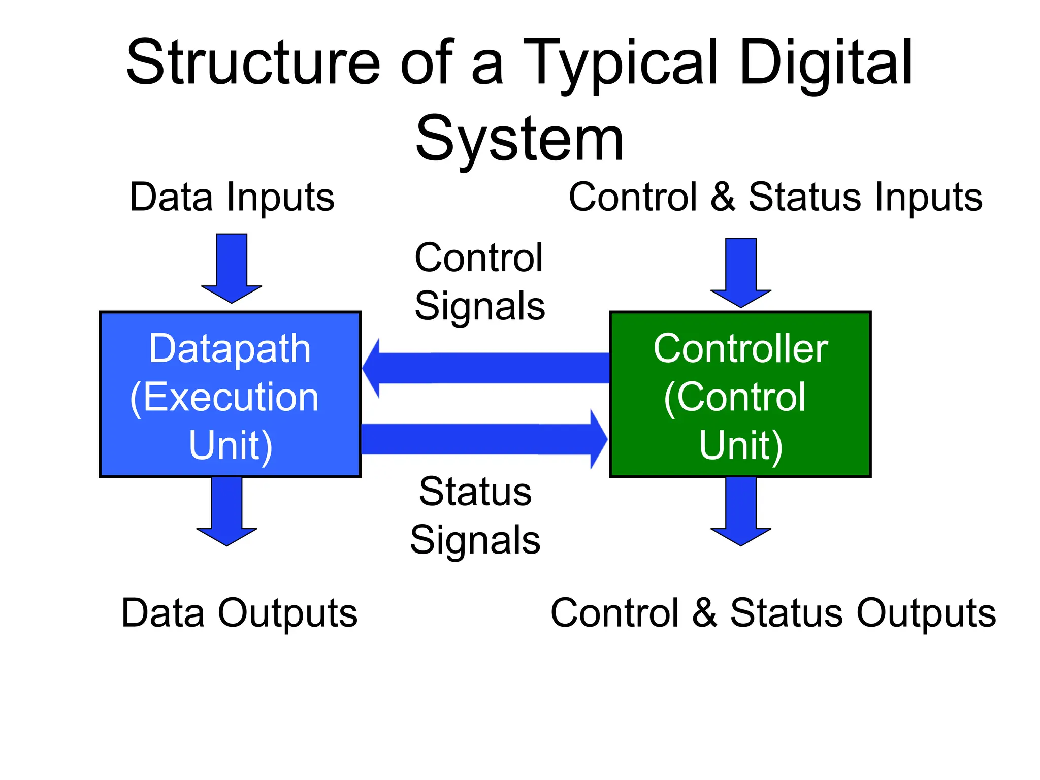
Structure of aTypical Digital
System
Datapath
(Execution
Unit)
Controller
(Control
Unit)
Data Inputs
Data Outputs
Control & Status Inputs
Control & Status Outputs
Control
Signals
Status
Signals
5.
5
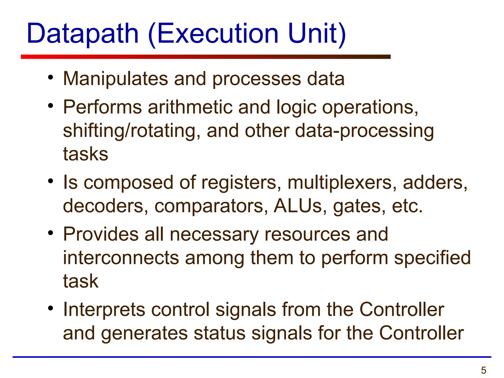
Datapath (Execution Unit)
•Manipulates and processes data
• Performs arithmetic and logic operations,
shifting/rotating, and other data-processing
tasks
• Is composed of registers, multiplexers, adders,
decoders, comparators, ALUs, gates, etc.
• Provides all necessary resources and
interconnects among them to perform specified
task
• Interprets control signals from the Controller
and generates status signals for the Controller
6.
6
Controller (Control Unit)
•Controls data movements in the Datapath by
switching multiplexers and enabling or disabling
resources
Example: enable signals for registers
Example: select signals for muxes
• Provides signals to activate various processing
tasks in the Datapath
• Determines the sequence of operations
performed by the Datapath
• Follows Some ‘Program’ or Schedule
7.
7
Programmable vs. Non-ProgrammableController
• Controller can be programmable or non-programmable
• Programmable
• Has a program counter which points to the next instruction
• Instructions are held in a RAM or ROM
• Microprocessor is an example of a programmable controller
• Non-Programmable
• Once designed, implements the same functionality
• Another term is a “hardwired state machine,” or “hardwired
FSM,” or “hardwired instructions”
• In this course we will be focusing on non-
programmable controllers.
8.
8
Finite State Machines
•Digital Systems and especially their Controllers can be
described as Finite State Machines (FSMs)
• Finite State Machines can be represented using
• State Diagrams and State Tables - suitable for simple
digital systems with a relatively few inputs and outputs
• Algorithmic State Machine (ASM) Charts - suitable
for complex digital systems with a large number of
inputs and outputs
• All these descriptions can be easily translated to the
corresponding synthesizable VHDL code
9.
9
ECE 448 –FPGA and ASIC Design with VHDL
Finite State Machines
Refresher
10.
10
Finite State Machines(FSMs)
• An FSM is used to model a system that transits
among a finite number of internal states.
The transitions depend on the current state and
external input.
• The main application of an FSM is to act as the
controller of a medium to large digital system
• Design of FSMs involves
• Defining states
• Defining next state and output functions
• Optimization / minimization
• Manual optimization/minimization is practical for small
FSMs only
11.
11
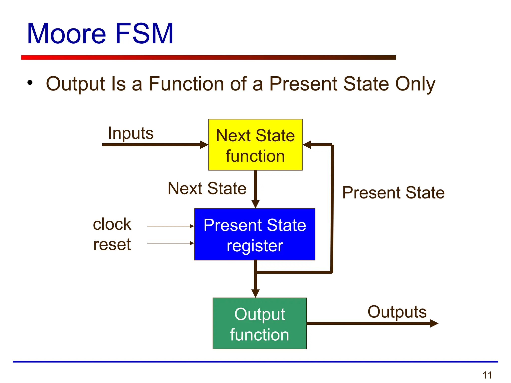
Moore FSM
• OutputIs a Function of a Present State Only
Present State
register
Next State
function
Output
function
Inputs
Present State
Next State
Outputs
clock
reset
12.
12
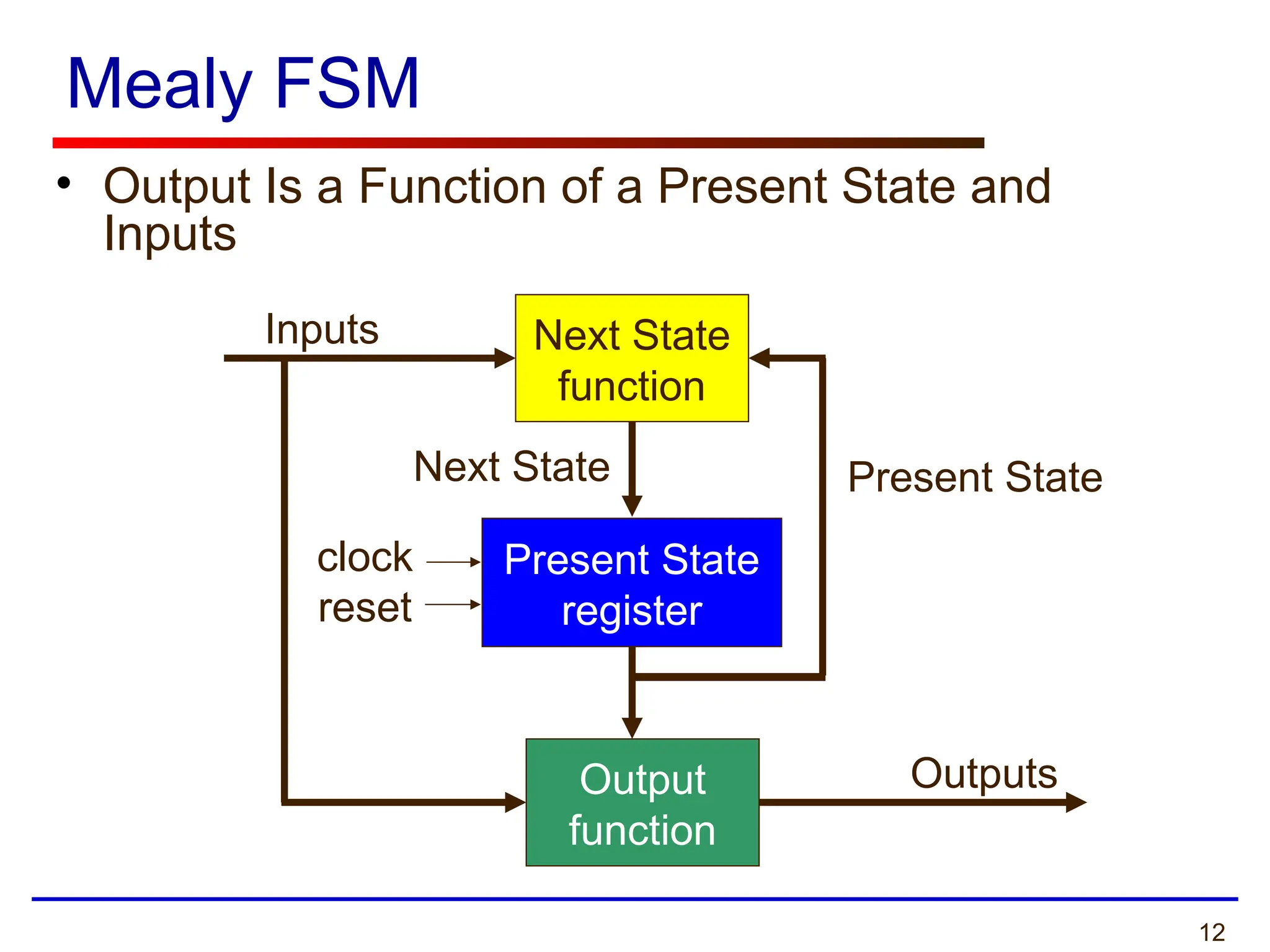
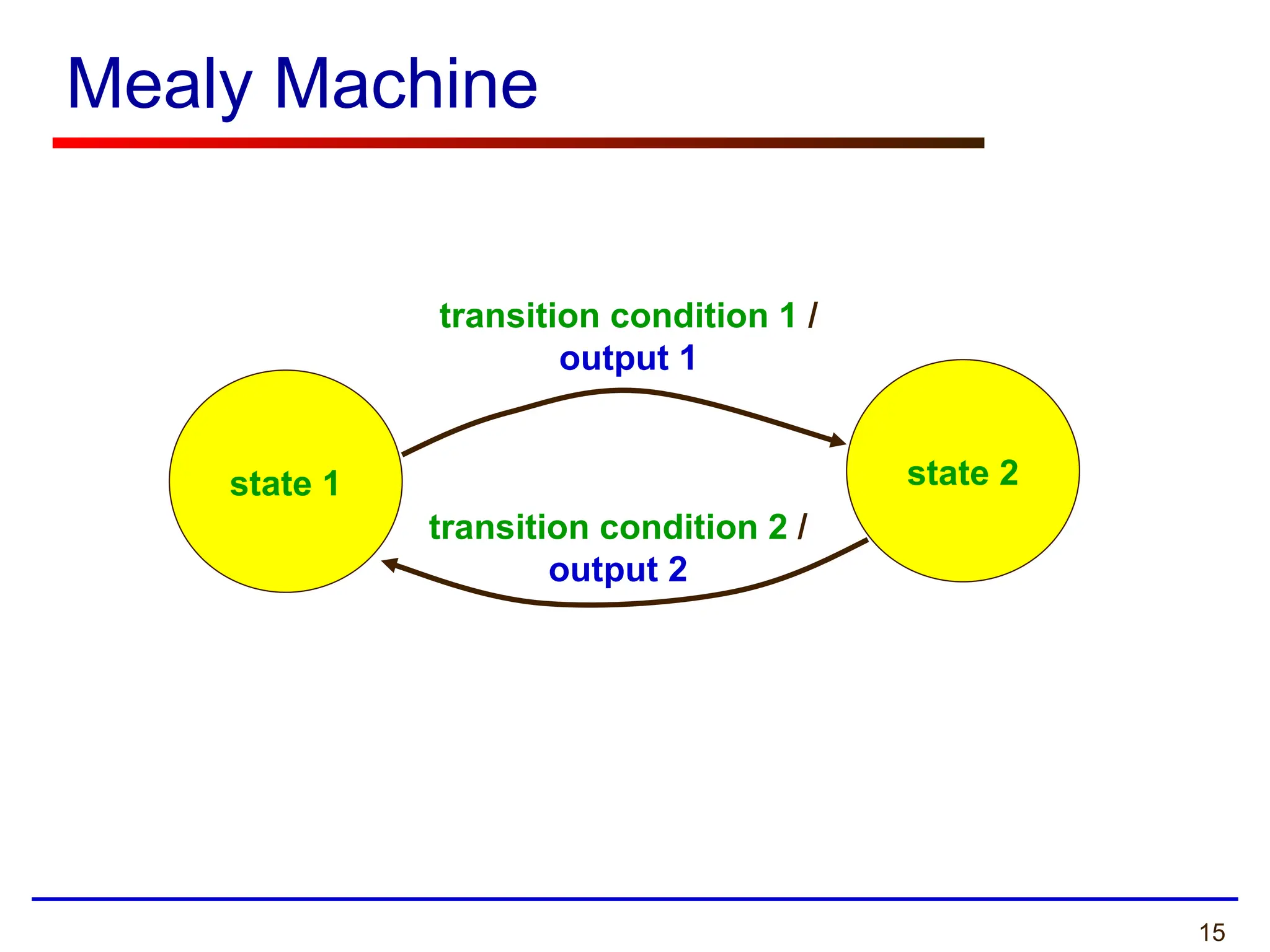
Mealy FSM
• OutputIs a Function of a Present State and
Inputs
Next State
function
Output
function
Inputs
Present State
Next State
Outputs
Present State
register
clock
reset
13.
13
ECE 448 –FPGA and ASIC Design with VHDL
State Diagrams
14.
14
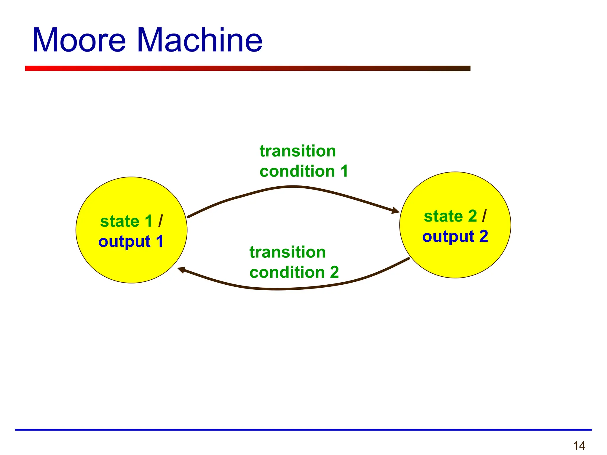
Moore Machine
state 1/
output 1
state 2 /
output 2
transition
condition 1
transition
condition 2
16
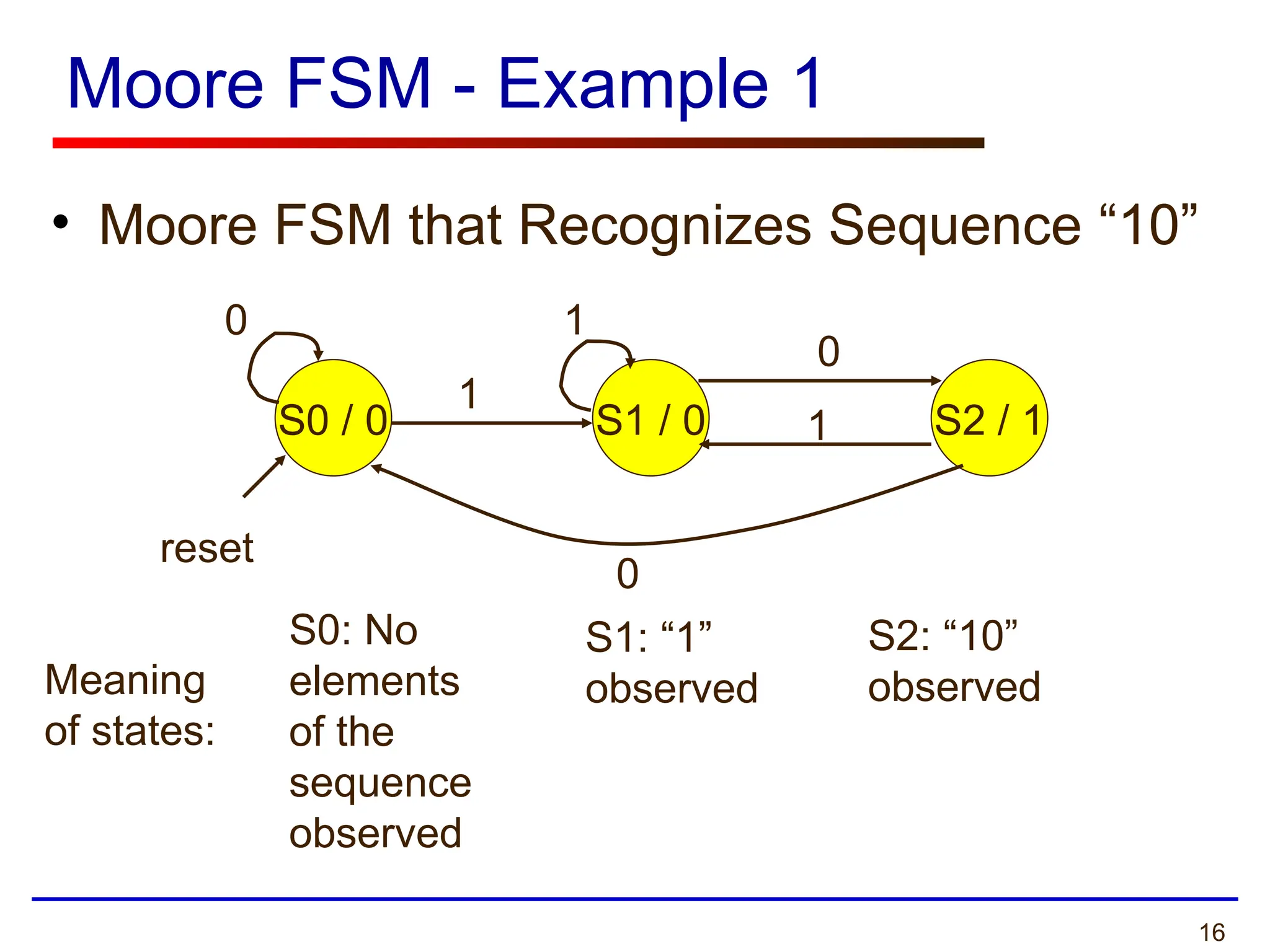
Moore FSM -Example 1
• Moore FSM that Recognizes Sequence “10”
S0 / 0 S1 / 0 S2 / 1
0
0
0
1
1
1
reset
Meaning
of states:
S0: No
elements
of the
sequence
observed
S1: “1”
observed
S2: “10”
observed
17.
17
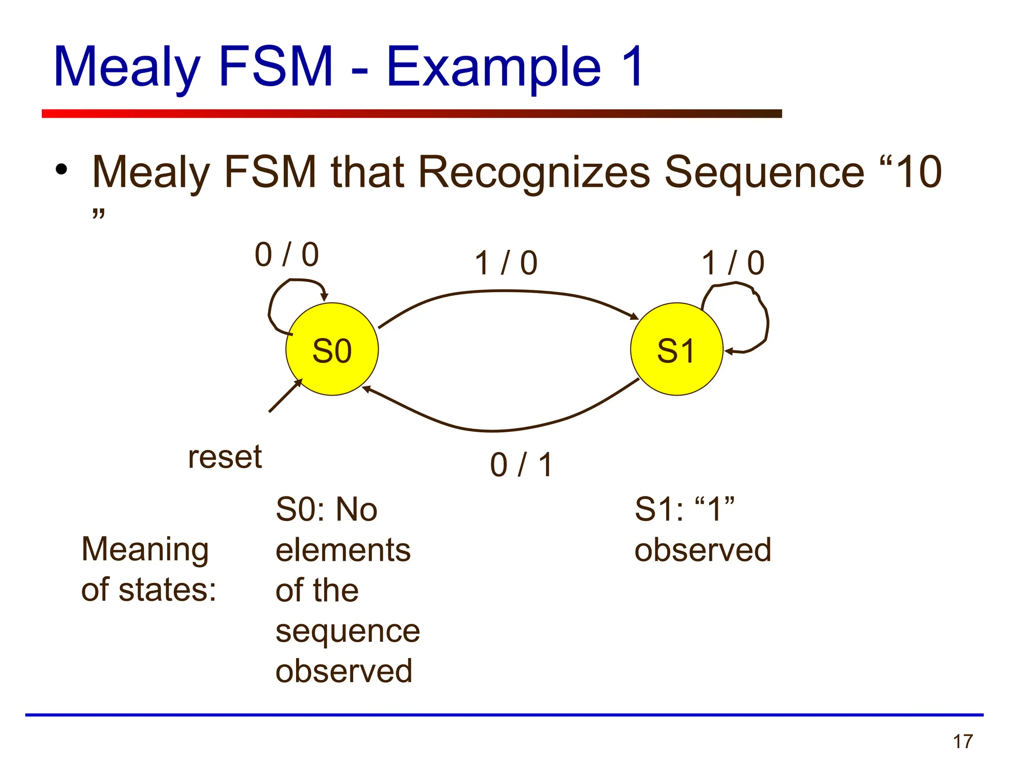
Mealy FSM -Example 1
• Mealy FSM that Recognizes Sequence “10
”
S0 S1
0 / 0 1 / 0 1 / 0
0 / 1
reset
Meaning
of states:
S0: No
elements
of the
sequence
observed
S1: “1”
observed
18.
18
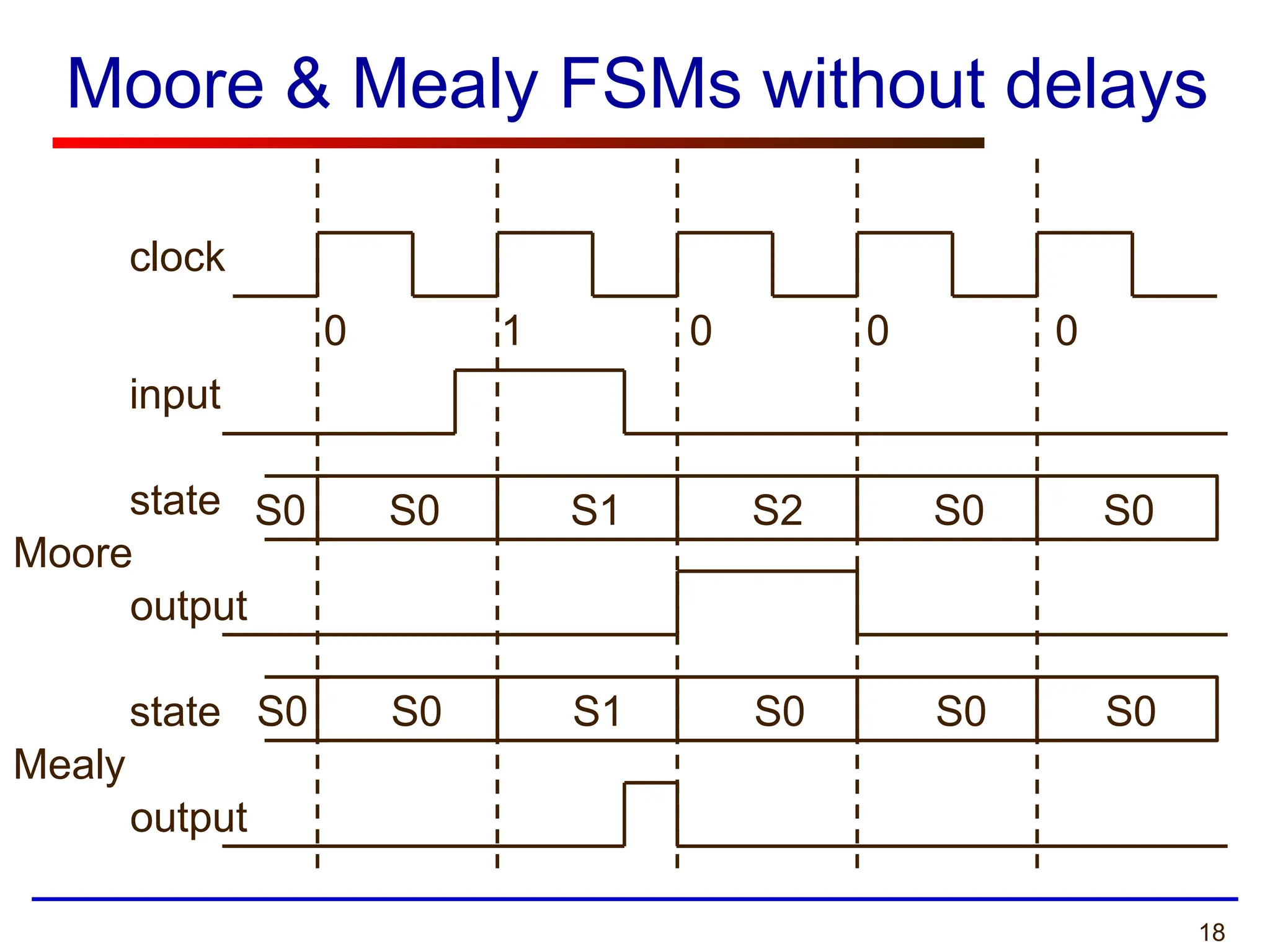
Moore & MealyFSMs without delays
clock
input
Moore
Mealy
0 1 0 0 0
S0 S0 S1 S2 S0 S0
S0 S0 S1 S0 S0 S0
state
output
state
output
19.
19
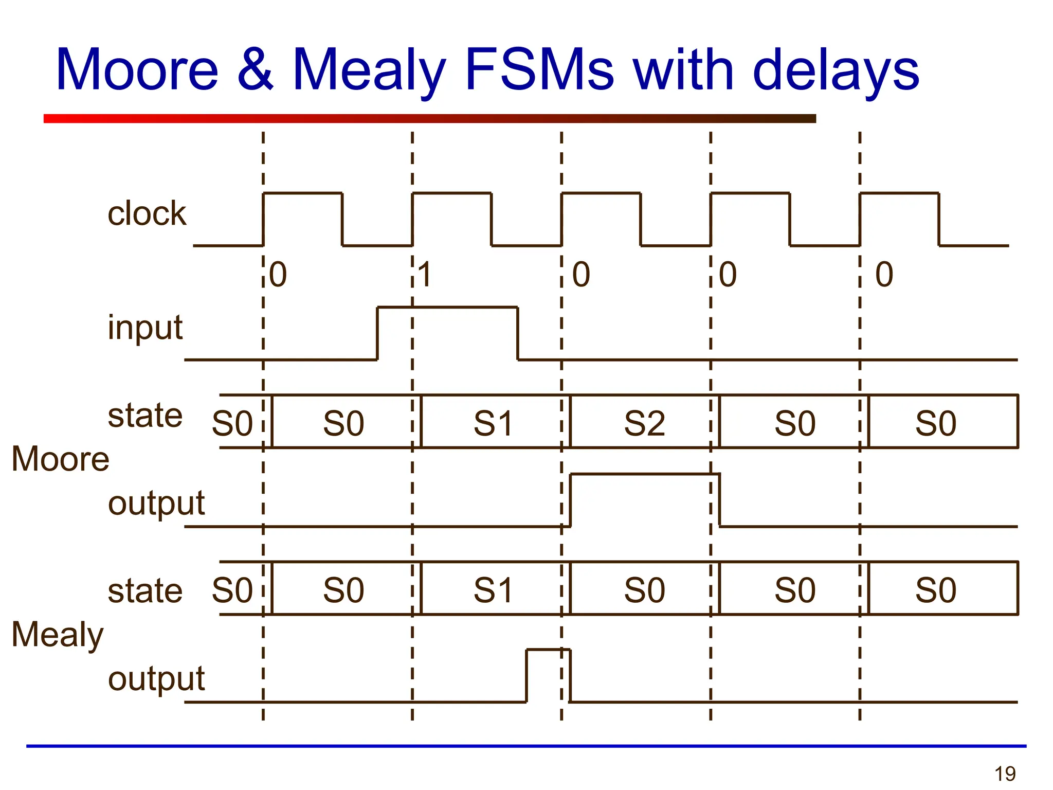
Moore & MealyFSMs with delays
clock
input
Moore
Mealy
0 1 0 0 0
S0 S0 S1 S2 S0 S0
S0 S0 S1 S0 S0 S0
state
output
state
output
20.
20
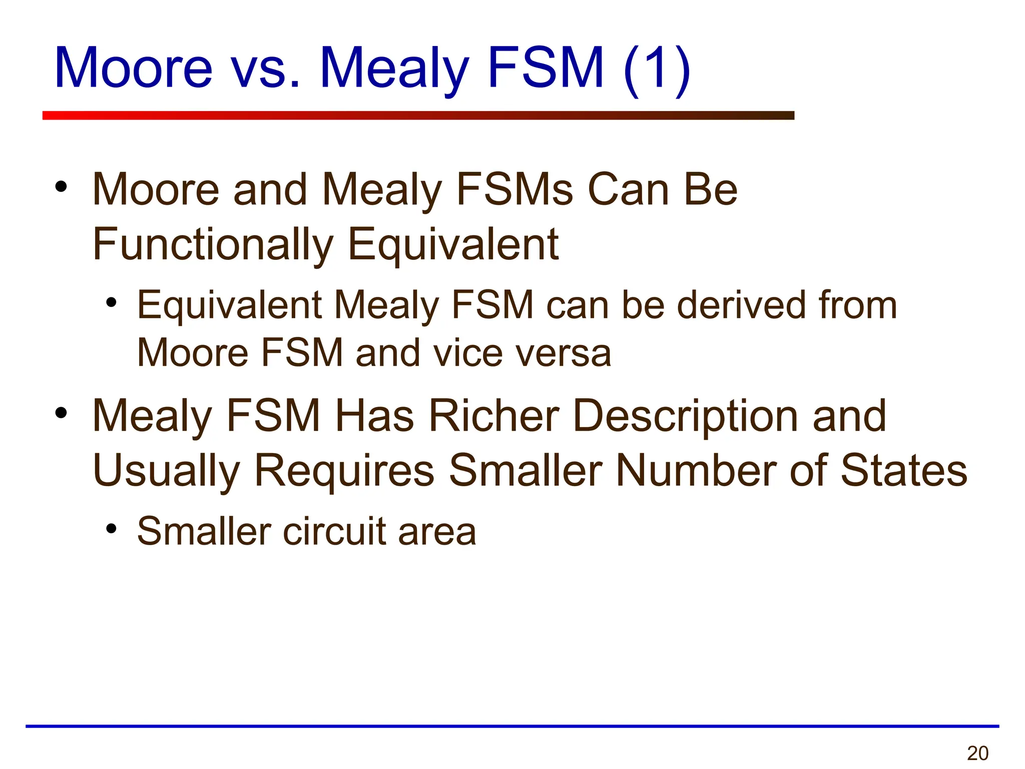
Moore vs. MealyFSM (1)
• Moore and Mealy FSMs Can Be
Functionally Equivalent
• Equivalent Mealy FSM can be derived from
Moore FSM and vice versa
• Mealy FSM Has Richer Description and
Usually Requires Smaller Number of States
• Smaller circuit area
21.
21
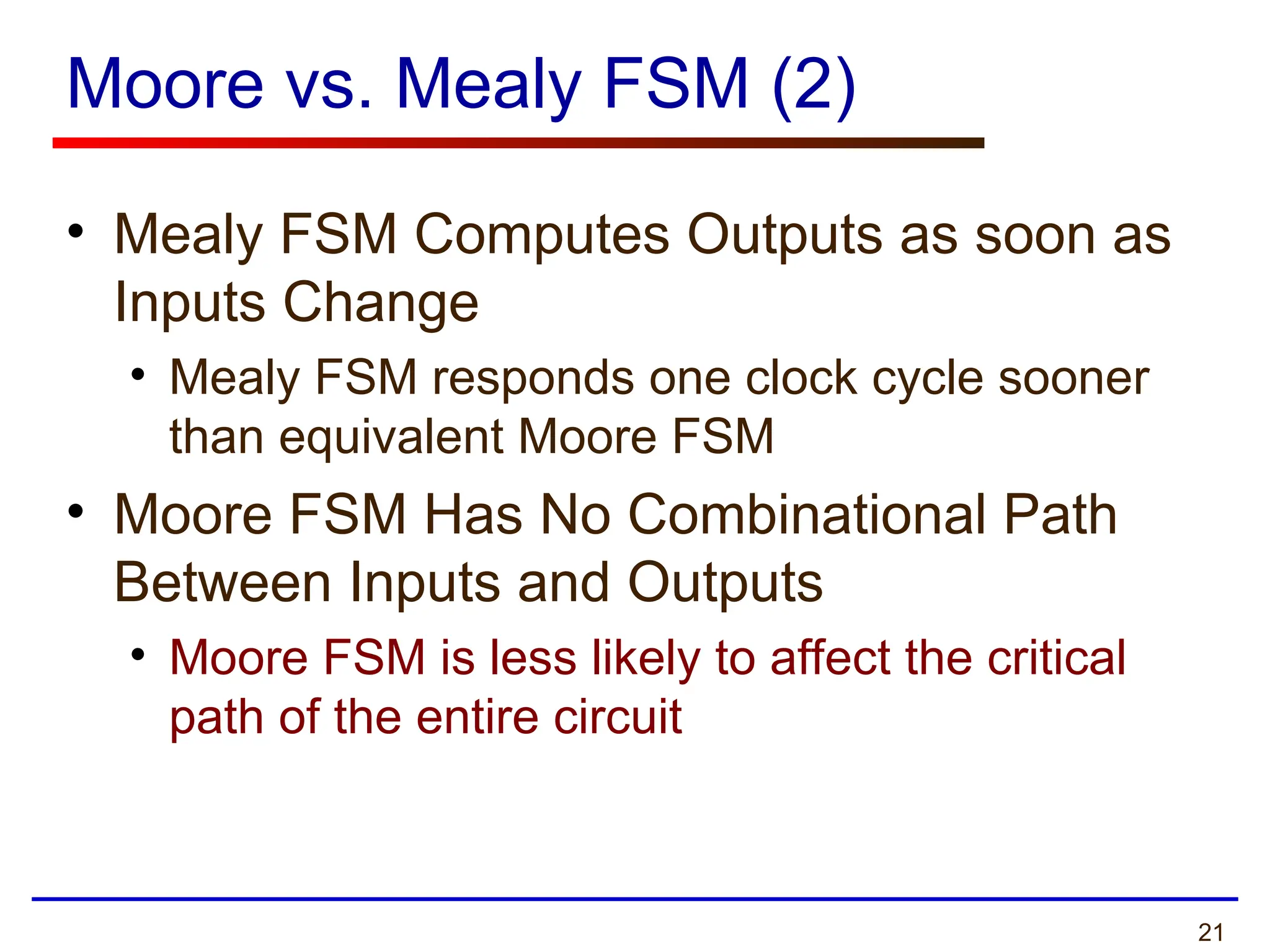
Moore vs. MealyFSM (2)
• Mealy FSM Computes Outputs as soon as
Inputs Change
• Mealy FSM responds one clock cycle sooner
than equivalent Moore FSM
• Moore FSM Has No Combinational Path
Between Inputs and Outputs
• Moore FSM is less likely to affect the critical
path of the entire circuit
22.
22
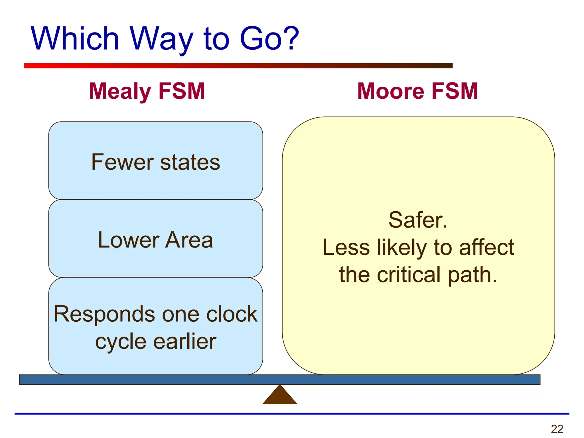
Which Way toGo?
Safer.
Less likely to affect
the critical path.
Mealy FSM Moore FSM
Lower Area
Responds one clock
cycle earlier
Fewer states
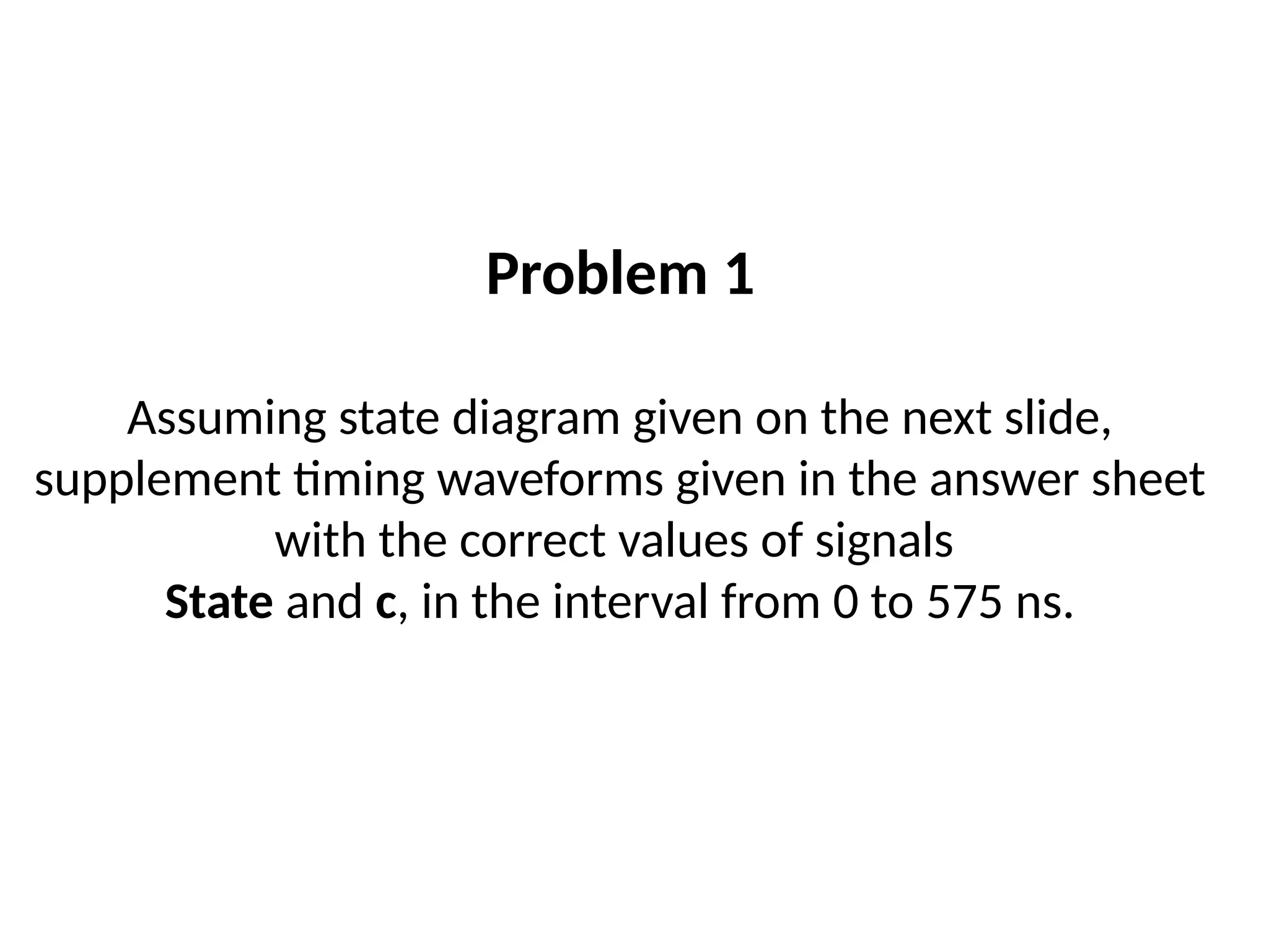
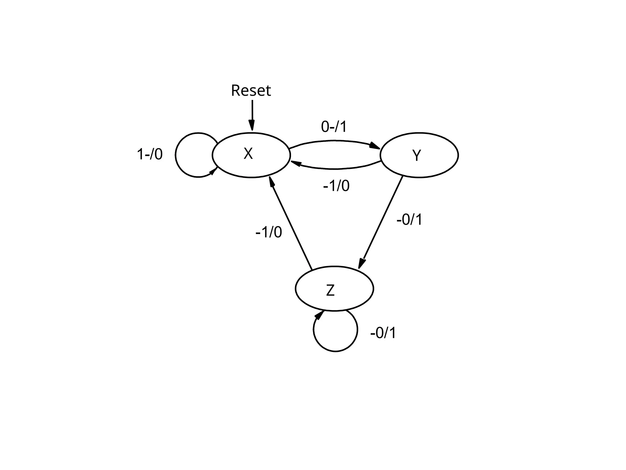
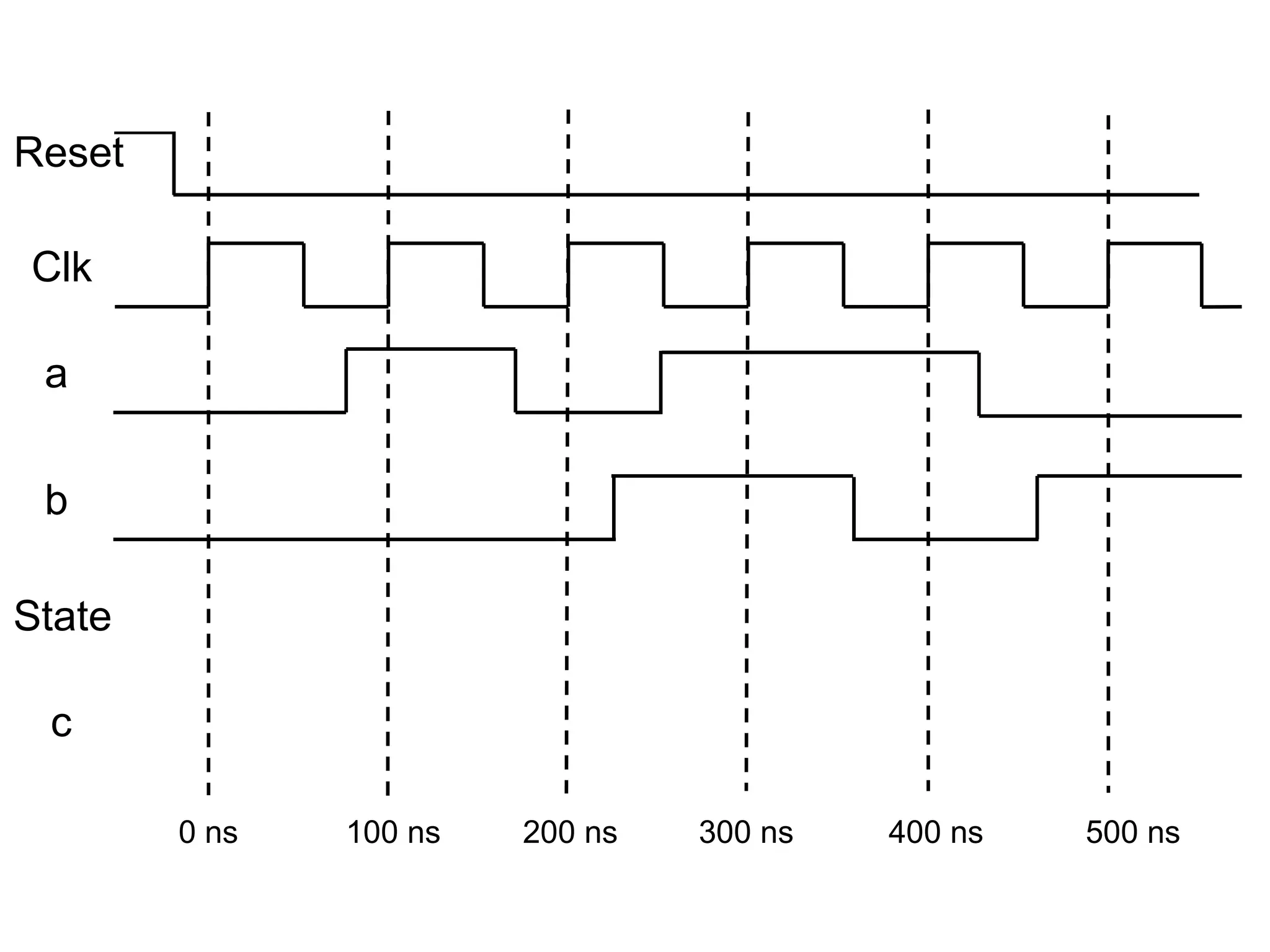
Problem 1
Assuming statediagram given on the next slide,
supplement timing waveforms given in the answer sheet
with the correct values of signals
State and c, in the interval from 0 to 575 ns.