Finite State Machine
FSMis a computational model used to describe the
behavior of a system through states and transitions.
Primary purpose is used for modeling and control of
systems.
Final result is that produces output for each state or
transition
Focus on emphasizes system behavior.
3.
Components of FSM
States: It describes current behaviour of machine.
Input : It describes input given to the machine.
State transition : It describes the changes in transition
Rules or condition :Rules or condition applied to machine.
Two functions :
MAF(Machine Function) :I x S -> O
STF(State Function): I x S -> S
where I :Input S : State O :Output
4.
Real Time Exampleof FSM
An elevator (lift) control system can be modeled as
a Finite State Machine (FSM) because it operates
with a finite number of states, and its behavior
changes based on inputs such as button presses.
5.
Real Time Exampleof FSM
A controller for an elevator
Two floors :Ground & First
Two buttons :Up & Down
Two lights :Red & Green
6.
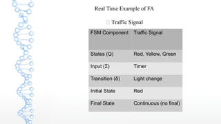
Real Time Exampleof FA
🚦 Traffic Signal
FSM Component Traffic Signal
States (Q) Red, Yellow, Green
Input (Σ) Timer
Transition (δ) Light change
Initial State Red
Final State Continuous (no final)
7.
Finite State Machine
FiniteState Machine is an abstract computational
model consisting of a finite number of states and `
It works by moving from one state to another based
on input. Traffic signal systems, vending machines,
and ATM machines are practical examples of FSM
where each operation follows a predefined sequence
of states.
8.
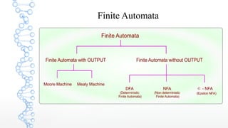
Finite Automata
Finite Automatais an abstract computing device.It is a
mathematical model of a system with discrete
inputs,outputs,states and set of transition from state to
state that occurs on input symbols from alphabet Σ.
It representations:
Graphical (Transition Diagrams of Transition Table)
Tabular(Transition Table)
Mathematical( Transition function of mapping
function)
9.
Finite Automata
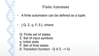
A finiteautomaton can be defined as a tuple:
{ Q, Σ, q, F, δ }, where:
Q: Finite set of states
Σ: Set of input symbols
q: Initial state
F: Set of final states
δ: Transition function : Q X Σ --> Q.