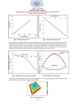
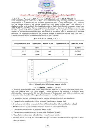
SlideShare a Scribd company logo
ISSN: 2319-5967
ISO 9001:2008 Certified
International Journal of Engineering Science and Innovative Technology (IJESIT)
Volume 4, Issue 5, September 2015
48
48
Finite ElementAnalysis of Doubly Curved
Thin Concrete Shells
Harish B. A1, N. Venkata Ramana2, K. Manjunatha3.
1. Assistant Professor, GM Institute of Technology, Davangere.
2. Associate Professor, Department of Studies in Civil Engg, UBDTCE, Davangere
3. Professor, Department of Studies in Civil Engg, UBDT College of Engineering, Davangere.
Abstract: A thin shell is a “Three-dimensional spatial structure made up of one or more curved surfaces whose
thickness is small compared to their other dimensions”. Shells belong to the class of stressed skin structures which,
because of their geometry and small flexural rigidity of the skin, tend to carry loads primarily by direct stresses acting in
their plane. The shells are subjected to pure membrane state of stress, under appropriate loading and boundary
condition the resulting bending and twisting moments are either zero or small which may be neglected. The coordinates
of funicular shells are determined by masonry mould method by developing a computer program. In this study doubly
curved thin shells are analysed using finite element software SAP 2000. Doubly curved shells which are in square plan
having 10mX10m and 15mX15m are considered and shells in rectangular plan having dimensions 10mX15m
and 15mX20m are considered. The behavior of shells under self-weight, live load varying from 0-20KN/m (UDL) is
obtained. In this case study deflection curves, membrane stress and stress contour diagram are obtained. It is observed
that with the increase in rise and thickness of funicular shell the deflection are reduced. The membrane stresses
decreases with the increase in rise and thickness of concrete funicular shell. The aim of this study is to develop shells of
different sizes and investigation is done on the shells by finite element analysis under given uniformly distributed load,
to find out the behavior of shells in various cases using standard software, Structural Analysis Package (SAP 2000).
Keywords: Funicular shell, Membrane theory, Finite element models, Discretization, SAP 2000.
I. INTRODUCTION
A shell structure is a three dimensional structure, thin in one direction and long in the other two directions. Such
structures are abundantly found in nature, the shell of an egg is an impressive example. Concrete shells include
single curved geometries such as cylinders and cones and double curved geometries such as domes, arches, vaults.
Although shell structure is thin and lightweight, hence they span over relatively large areas, and support applied loads
in a very effective way. It seems that with shell structures, nature have maximized the ability to span over large areas
with a minimum amount of material. Thin shells provide in an advantageous low consumption of material. The low
consumption of material in shell structures follows from the unique character of the shell i.e. the geometry which is in
curvature in spatial form. This unique character the shell structures are very efficient in carrying loads acting
perpendicular to their surface by so-called membrane action. Modern shell structures can span larger column-free
areas and, with thinner thicknesses than the traditional domes. The desire to reduce the thickness is understandable as
the dead weight of the shell represents the major portion of the total load. Moreover, the preference for membrane
action arises as a consequence of being thin. Most of the different types of superstructures we commonly used for
present day building are only a modification of the age old system of column, beam and roof covering arrangements.
They fulfil their function by two separate systems. One is the space covering system to cover the space, such as
concrete slab or roof covering sheets in steel building. These are supported by a second system of beams and columns
which we may call the supporting system. In many steel buildings they are obviously separate and in R.C buildings also,
they are treated as two separate systems. In reinforced concrete shells, however, the two functions of covering the
space and supporting the covering system are integrated into one. The structure covers the space without beams and
columns within the buildings. There are several different styles of concrete shell, including the dome, the barrel shell,
and the folded plate. They can be elaborate or utilitarian, depending on the intended use, construction budget, and
space requirements. For the most part, these structures do not have buttresses on the exterior or interior supporting
columns. As the structure often must provide its own support, it is important that concrete shells be carefully designed for
proper weight distribution, durability, and stability. A typical view of funicular shells used for a roof construction is
shown in figure 1.
ISSN: 2319-5967
ISO 9001:2008 Certified
International Journal of Engineering Science and Innovative Technology (IJESIT)
Volume 4, Issue 5, September 2015
49
49
Fig.1:- Typical view of funicular shell
II. LITERATURE REVIEW
The selection of available documents (both published and un published) on the topic, which contain information,
ideas, data and evidence written from a particular standpoint to ful fill certain aims or express certain views on
the nature of the topic and how it is to be investigated, and the effective evaluation of these documents in
relation to the research being proposed. A literature review is a survey of already existing writings (usually
published) on a given topic or area with a view to assessing their relevance to a proposed project. The behavior
of prefabricated shell units has been investigated, both theoretically and experimentally, by many researchers.
Apart from construction schemes, the use of pre-fabricated shell units creates certain problems which have to be
investigated from the research point of view. One of the most important is the structural behavior of the units
when subjected to the concentrated loads at various points along their span. Another consideration of interest is
the ultimate strength and pattern of failure for these types of shells. The shells of double curvature usually offer
a higher ultimate strength than the shells of single curvature, such as cylindrical shells. The funicular shell roof is
one such compression structure, which ensures conservation of natural resources by utilizing waste materials
effectively and optimizing the use of expensive steel and cement. Further, the arch distributes the point load in
all direction equally thus, is able to withstand impact loading at any point. Diagonal grid of funicular shell gives
the illusion of a larger space.
III. REVIEW OF SELECTED TECHNICAL PAPERS
Odello, Robert J, Allgood J. R. (1970) Research is described in which a concrete funicular shell, 35 x 40 feet
in plan with a 2-inch thickness and a 30-inch rise, was tested to define its behaviour under various loadings. The
shell sustained a uniformly distributed load of 135 psf before failing in local buckling. In a subsequent test on
an undamaged portion, it sustained a concentrated load of 10,800 pounds over an area 6 inches square before
failing in punching shear. In addition to the test, pertinent construction and analysis techniques are discussed. It
was found that double-curved shallow shells may be easily cast over an earth mound. When combined with the
lift-slab technique, this mode of construction is expected to provide an inexpensive method for fabricating
large shells for floors and roofs. Approximate limit analyses can be used to proportion shallow shells for
ordinary purposes; however, no completely satisfactory method is available for treating such members. Elastic
analysis provides a reasonable representation of behaviour only at low loads. Despite the limitations in current
analysis, the technology has developed sufficiently to permit use of shallow shells in military and civilian
construction. Naval Shore Establishment uses include decks of docks and floors and roofs of warehouses.
Zacharia George, V.S. Parameshwaran and B.R. Rama Murthy (1971) the paper describes in detail the
salient features in the design construction of the building. A structure testing laboratory has been constructed
recently for the Structural Engineering Research (Regional) Centre in madras. It has three large funicular shells
built of brick for its roof. The structural frame is designed using the ultimate strength design procedure and high
strength deformed bars. The concrete used has an as cast‟ finish. Three shells, each 13.50 m X 12.00 m in size,
form the roof of the building. The funicular shell developed by the SERC has been used for a large variety of
structural floors and roofs in the form of precast elements for roofs and floors, and also as large cast in situ shells
for roofs. Because of the funicular shape, the shell is practically free from flexural moments, and is subjected
mainly to membrane compressive stresses. Moreover, the compressive stresses are very low. This property
ISSN: 2319-5967
ISO 9001:2008 Certified
International Journal of Engineering Science and Innovative Technology (IJESIT)
50
50
Volume 4, Issue 5, September 2015
renders the shells suitable for being built with materials of low compressive strength, such as bricks. When used for
roofing industrial buildings, the higher thermal insulation value of the bricks is an added advantage. The roof is
designed to carry a live load of 75 kg/m2, and the weight of bitumen felt waterproofing on top, in addition to its
self-weight. Although the shell does not need any reinforcement in its body to carry static loads, reinforced
concrete ribs, spaced at 1m centres both ways, are incorporated in the 10cm thickness of the shell. These ribs are
provided as a safeguard against vibrations which may be transmitted to the roof by the pulsator on the test floor
and by the movement of the EOT crane over the supporting columns. They are inset 1cm from the soffit of the
shell to emphasise the grid pattern.
Albolhassan Vafai and M ehdi Farshad (1979) have done a research work on theoretical and experimental
study of prefabricated funicular shell units. This paper presents the results of a theoretical and experimental
study of funicular shell structures. A particular design is given for the geometry, the form, and the type of
reinforcement of the units. Ten models are constructed based on this design. First, six samples supported at two
edges are loaded to a specified load within the elastic region. Electrical resistance gauges are mounted both
inside and outside at several locations on the surface of the shell on two different specimens. Also, dial gauges are
installed at several locations on the surface of four shells. Following these non-destructive tests, all ten samples are
loaded to failure, subjected to a concentrated load at the center. To relate experimental results to theory, the finite
technique is utilized to analyse a similar model. The experimental values of membrane stresses along the central
section in the direction of the supports are calculated and compared with the theory. The results are in close
agreement at some distance away from the supports, but the difference becomes noticeable closer to the support.
The same phenomenon appears to be true when the experimental values of vertical deflections along the
longitudinal and transverse sections of the shells are compared with the theory. Also, the experimental failure
loads are found to be directly related to the amount of reinforcement, and the age of the concrete shells.
John W. Weber, Kwong-chi Wu and AdholhassanVafai (1984) have done an evaluation of ultimate loads for
shallow funicular concrete shells. Shells belong to the class of stressed skin structures which, because of their
geometry and small flexural rigidity of the skin, tend to carry loads primarily by direct stresses acting in their
plane. Ten shallow funicular concrete shells were loaded to failure with a concentrated central force. Five shells
were randomly reinforced with steel wires and the reminder with a wire mesh through the middle surface. All of the
shells were 90 cm x 90 cm in plan form. Strain gauges showed a linear relationship between load and strain in the
elastic range of the concrete, whereas measured deflections were larger than those determined analytically by small
deflection theory, would be more appropriate for theoretical investigations of shallow funicular shells subjected
to large concentrated loads. Ultimate loads were not clearly related to type of reinforcement, but were a function of
the rise and thickness of the shell in general the larger the rise parameter (square of the ratio of rise to thickness),
the larger the ultimate load. Failure patterns for shells with both kinds of reinforcement were the same. They
observed that the mathematical investigations of shallow funicular shells with large concentrated loads should be
based on large deflection theory and the deflection characteristics of a shell vary closely with its rise parameter.
Suresh, Desai and G.S. Ramaswamy (1985) This paper gives the details like theory of funicular shell, method of
construction and shape generation of thin, shallow, funicular concrete shells by the finite element technique.
Funicular shells are thin shallow concrete shells in which a state of equal biaxial compression develops under
vertical loading. Large funicular shells may be cast on accurately-cut forms profiled to the funicular shape. This
procedure requires a computation of accurate values of ‘Z’ for the commonly encountered aspect ratios. The
table is prepared by using both the finite element method and the energy method. The two sets of values are in
close agreement. The concept of funicular shells was initiated by Ramaswamy. A simple technique of letting a
thin shell cast itself to the funicular shape has been developed and patented in India. The technique involves
loading a flexible fabric stretched across a mould with wet concrete. The concrete, being wet, carries no load at
this point. The fabric carries the load in tension and sags to generate the funicular shell over a ground plan
whose form is determined by the shape of the mould. T wenty four hours after casting, the shell is inverted and
taken off the mould. It is easy to see that the weight of the shell will now be carried by the concrete in compression.
The same reasoning would apply to other vertical loads applied to the shell. No distinction need be made
between uniform vertical loads and snow loads, if the shell is shallow. Finally they concluded that Reinforced
concrete will continue to dominate the construction scenario in coming decades on a scale larger than has been
witnessed at the present. This gives the vast scope to the engineers in the academic and the construction field to
51
51
ISSN: 2319-5967
ISO 9001:2008 Certified
International Journal of Engineering Science and Innovative Technology (IJESIT)
Volume 4, Issue 5, September 2015
endeavour, with concerted efforts, to make the material more economic and more versatile in its presented by
Ramaswamy. These values are enclosed in parentheses in Table1. The agreement between the two sets of values is
very close and it is inferred that the finite element values are accurate enough for use in the field for the
manufacture of forms.
Ramaswamy (1986) this article provides the information about innovative applications of funicular shells. In
Civil Engineering practice, concrete thin shells are normally used only as roofs to carry relatively light loads,
because most shell forms develop sizable bending stresses when submitted to heavy loads, making them
unsuitable as intermediate floors of industrial and institutional buildings. The funicular shell described in this
paper is an exception. Its use in Civil Engineering practice can extend the frontiers of application of concrete
thin shells to intermediate floors, loading platforms to carry heavy warehouse loading, foundation footings of
tall chimneys, foundation rafts, and bridge decks and water tanks. In this paper, some of these possibilities are
briefly outlined. The normal sequence followed in designing concrete shells is to assume their geometry and
topology to start with. A stress analysis is next carried out. There are definite advantages to be gained in
reversing this sequence. Thus, we may assume a desired state of stress under a specified condition of
loading, to begin with and then proceed to arrive at the appropriate shape. Shapes so found have been
designated as funicular shells by Ramaswamy. The desired state of stress in concrete thin shells is equal biaxial
compression, unaccompanied by shear, so that tensile stresses do not develop. The allowable compressive stress in
both the directions is limited to what the material can safely carry. It is easy to see that such a prescription of
stresses lead to a fully stressed design. Consequently, funicular shells are optimal structural forms. Shapes of
funicular shells may be found by analytical or experimental means.
S.Elangovan and A.R.Santhakumar (1988) have done a research work on parametric study of funicular
shells. The funicular shell was analysed by the finite element method using isoparamertic elements with five
degrees of freedom at each node. A computer programme developed by the authors was used in the analysis of
funicular shells with clamped boundaries. The behavior of the shell under uniformly distributed load, for various
ratios of spans and rise/span was studied analytically. Approximate expressions for the calculation of bending
moment at the edge of the shell, in-plane force at crown, and deflection at crown had been proposed. The
funicular shell is a shallow shell of double curvature. The shape of such shells to suit any boundary geometry
can be found by analytical or experimental methods. The behavior of the shell under uniformly distributed load,
for various ratios of spans and rise/span was studied analytically. The load applied was within the elastic range
and hence, the deflections, forces, and moments are proportional to the load. So the intensity of the uniformly
distributed load was taken equal in all cases.
52
52
ISSN: 2319-5967
ISO 9001:2008 Certified
International Journal of Engineering Science and Innovative Technology (IJESIT)
Volume 4, Issue 5, September 2015
IV. METHODOLOGY
Funicular shells in square and rectangular ground plan are considered for the investigation. Numerical approach
using advanced finite element analysis based software called as SAP 2000 is adopted. Based on reported
literature of similar nature a FE model is developed and a study is conducted to investigate the behaviour of
funicular shells under uniformly distributed load.
V. EXECUTION OF PROGRAM
The model consisted of a funicular shell uniformly loaded at its top. The finite element technique and a related
computer program (SAP 2000) were utilized to analyze structure. The finite element model used to analyse the
shell is based on the assumption that the material is linearly elastic. Hence, the theoretical prediction is expected
to be valid only in the elastic region of the shell behavior. The plan of the shell, its dimensions and other
dimensions are represented in the Table No.1, and fig 2 shows a four noded quadrilateral element.
Fig.2:- Four noded quadrilateral shell element
Table No.1:- Shell Dimensions
Geometry Designation Plan (m) Rise (mm) Thickness (mm)
Square
FS I 10X10 1000 50
FS II 10X10 1500 50
FS III 10X10 2000 50
FS IV 15X15 1000 50
FS V 15X15 1500 50
FS VI 15X15 2000 50
Rectangle
FS VII 15X10 1000 50
FS VIII 15X10 1500 50
FS IX 15X10 2000 50
FS X 20X15 1000 50
FS XI 20X15 1500 50
FSV XII 20X15 2000 50
53
53
ISSN: 2319-5967
ISO 9001:2008 Certified
International Journal of Engineering Science and Innovative Technology (IJESIT)
Volume 4, Issue 5, September 2015
The finite element model of funicular shell with different ground plan is developed by using SAP 2000 finite
element package is shown in Figure 3 to 5.
Fig.3:- Square funicular shell Fig.4:- Hinge support at all the edges
Fig.5:- Discretized model and corresponding node numbers.
ISSN: 2319-5967
ISO 9001:2008 Certified
International Journal of Engineering Science and Innovative Technology (IJESIT)
Volume 4, Issue 5, September 2015
54
54
Load
(KN/m)
Stress
(KN/m2)
Deflection
(mm)
0 0.156 -0.1123
1 0.2432 -0.1997
2 0.3304 -0.2871
3 0.4176 -0.3745
4 0.5048 -0.4619
5 0.592 -0.5493
6 0.6792 -0.6367
7 0.7664 -0.7241
8 0.8536 -0.8115
9 0.9408 -0.8989
10 1.0127 -0.9864
11 1.09828 -1.0737
12 1.18379 -1.1611
13 1.2693 -1.2485
14 1.35481 -1.3359
15 1.4403 -1.4233
16 1.5258 -1.5107
17 1.6113 -1.5981
18 1.6968 -1.6855
19 1.7823 -1.7729
20 1.8678 -1.8606
VI. RESULTS AND DISCUSSION
Shells of various sizes were modelled and analyzed for various conditions. The shell is simply supported at all
the four edges. Since the stresses are more at the edges, edge beam is place at the edge to reduce stress. The
shells are subjected to given uniformly distributed load. From test specimens values of stresses and deflections
for different loadings were recorded. From the stress and deflection values graph is potted, funicular shells are
loaded up to 20 KN/m. It is observed that the deflection of the shell due to applied loads is small. From
results obtained it is found out that when the shell thickness is reduced the deflection of the increases for the
same applied load. Also the deflection reduces with increase in rise (R) of the shell. Deflection is more in
shell center compared to other points in the shell membrane.
Analysis of funicular shells with varying rises
Square shell of size 10X10 profile:
The Funicular shell over square ground plan were modelled with the corresponding varying rises 1m, 1.5m, 2m.
The shell is supported along its all four faces. The thickness of the shell is uniform throughout, with an edge beam
along the edges of four faces. A plot is made with size of the shell to varying sizes of the funicular shell to
know the shell profile of size 10m X 1 0 m. Figure.6 shows the profile of square funicular s h e l l o f s i z e
10mX10m.
Table No.2:- Max Stresses and Deflection for FS I
Fig.6:- 10mX10msquare shell with various rise
ISSN: 2319-5967
ISO 9001:2008 Certified
International Journal of Engineering Science and Innovative Technology (IJESIT)
Volume 4, Issue 5, September 2015
55
55
Fig.7:- Maximum stress for FS I Fig.8:- Maximum deflection for FS I
From the analysis of funicular shell over square ground plan FS I is made and the results of the analysis a plot is
made between the distance from the center of the shell and membrane stress distribution along the direction i,j
for S23 as shown in fig 9. From the analysis results, the deflections of the concrete funicular shell over
square ground plan along vertical direction are calculated and a plot is made between the various points
considered along the span of the shell to the corresponding deflections as shown in Fig 10.
Fig.9:- Membrane stress curve along i,j directions Fig.10:- Deflection curve along i &j
A stress contour for maximum tensile stress of Funicular shell I over square ground plan is shown in fig 11. The
maximum value of tensile stress is observed at the corners.
Fig.11:- Stress contour, FS I
ISSN: 2319-5967
ISO 9001:2008 Certified
International Journal of Engineering Science and Innovative Technology (IJESIT)
Volume 4, Issue 5, September 2015
56
56
Analysis of square Funicular shell IV, Funicular shell V, Funicular shell VI (FS IV, FS V, FS VI)
Finite element analysis is carried out on three various maximum rises by uniformly distributed load. From the
analysis results, it is observed that the membrane stresses S11 and S22 along the direction i and j, decreases
with the increase in rise of the shallow funicular shell over square ground plans. From the results of
displacements due to the uniformly distributed load applied on shallow funicular shell over square ground plans
of FS IV, FS V and FS VI for the same magnitude, the deflections are decreased with the increase in rise. From
the table a plot is made between, deflections and span / rise ratio (λ). The span to rise ratio has considerable
influence in the maximum deflection of shell. The increase in shell rise is result in the reduction of maximum
deflection. The reduction in deflection is also means the stiffness increase in the funicular shell. From figure.12
it is observed that deflection increases with the increase in span / rise ratio.
Table No.3:- Results of FS IV, FS V, FS VI
Designation of the shell Span in mm Rise (R) in mm Span/rise ratio (λ) Deflection in mm
FS IV 15000 1000 15 1.374769
FS V 15000 1500 10 0.630883
FS VI 15000 2000 7.5 0.364606
Fig.12:- Relation between Deflection and Span/rise ratio (λ)
VII. SUMMARY AND CONCLUSIONS
An analytical investigation has been carried out to study the behaviour of funicular shells with varying sizes,
rises and thickness using SAP 2000 software. Various parameters like variation of deflection, stress
distribution have been obtained in this study. The behaviour of funicular shell under uniformly distributed load
is presented in this study. The following conclusions are drawn fromthe test results:
1. It is observed that with the increase in rise of funicular shell the deflection of shell are reduced.
2. The membrane stresses decreases with the increase in rise of concrete funicular shell
3. It is observed that with the increase in thickness of funicular shell the deflection of shell are reduced.
4. Membrane stresses decreases with the increase in thickness of concrete funicular shell.
5. The maximum tensile stresses are developed at shell corners.
6. The maximum compressive stresses are observed at the edges of the shell.
7. The deflections and stress are reduced with use of reinforcement in shells.
8. From the present case study it is observed that the span to rise ratio should be minimum as possible to obtain
better performance.
ISSN: 2319-5967
ISO 9001:2008 Certified
International Journal of Engineering Science and Innovative Technology (IJESIT)
Volume 4, Issue 5, September 2015
REFERENCES
[1] Abolhassan Vafai, Massoud Mofid, “Experimental study of prefabricated funicular shell units”, Engineering
Structures, Vol19, No. 9, 1997, Pages 748-759.
[2] Abolhassan Vafai, Massoud Mofid and Homayoon E.Estekanchi, “Experimental study of prefabricated
funicular shell units”, Journal of Structural Engineering, Vol 19, No 9, 1997, Pages 748-759.
[3] Albolhassan Vafai and Mehdi Farshad “Theoretical and experimental study of prefabricated funicular shell units”,
Building and Environment, 1979, Vol 14, Pages 209 -216.
[4] G.S. Ramaswamy, N.V. Raman and Zacharia George “A Doubly-Curved funicular shell roof for a cement store”,
Indian Concrete Journal, January 1961, Pages 20-23.
[5] John W. Weber et al, “Ultimate Loads for Shallow Funicular Concrete Shells”, Northwest, Volume. (58), No. 3, 1984,
Pages 187 – 194.
[6] P. Sachithanantham, S. Elavenil and S. Sankaran “Study on funicular concrete shells over ground plan subjected to
ultimate loads”, International Journal of Earth Sciences and Engineering, ISSN 0974-5904, volume 04, No 06 SPL,
October 2011, Pages 632-637.
[7] Ramaswamy G.S, “Design and construction of concrete s h e l l Roof”, CBS publishers, 1986.
[8] S. Rajasekaran an d P . Sujatha, “Configuration of d eep funicular shells by boundary integral element method”,
Journal of Structural Engineering, Vol 9, No 1, April 1992 Pages 37-46.
[9] IS: 2210-1988, “Criteria for design of reinforced concrete shell structures and folded plates”, Bureau of Indian
Standards, 1989.
[10] IS: 6332-1984, “Code of practice for construction of floors and roofs using precast doubly curved shell units”, Bureau
of Indian Standards, 2000.
57

More Related Content

What's hot

87 fluid dampers seismic-protection_woodframestruct
87 fluid dampers seismic-protection_woodframestruct87 fluid dampers seismic-protection_woodframestruct
87 fluid dampers seismic-protection_woodframestruct
ceginc
 
Seismic response of frp strengthened rc frame
Seismic response of frp strengthened rc frameSeismic response of frp strengthened rc frame
Seismic response of frp strengthened rc frame
iaemedu
 

What's hot (20)

EFFECT OF SHEAR WALL AREA ON SEISMIC BEHAVIOR OF MULTI STORIED BUILDINGS WITH...
EFFECT OF SHEAR WALL AREA ON SEISMIC BEHAVIOR OF MULTI STORIED BUILDINGS WITH...EFFECT OF SHEAR WALL AREA ON SEISMIC BEHAVIOR OF MULTI STORIED BUILDINGS WITH...
EFFECT OF SHEAR WALL AREA ON SEISMIC BEHAVIOR OF MULTI STORIED BUILDINGS WITH...
 
Review on Structural Performance of Braced Steel Sturtures Under Dynamic Loading
Review on Structural Performance of Braced Steel Sturtures Under Dynamic LoadingReview on Structural Performance of Braced Steel Sturtures Under Dynamic Loading
Review on Structural Performance of Braced Steel Sturtures Under Dynamic Loading
 
aaaaaaaaaaaaaaaaaaaaaaaaaaaaaaaaaaaaa
aaaaaaaaaaaaaaaaaaaaaaaaaaaaaaaaaaaaaaaaaaaaaaaaaaaaaaaaaaaaaaaaaaaaaaaaaa
aaaaaaaaaaaaaaaaaaaaaaaaaaaaaaaaaaaaa
 
Research non seismic walls
Research  non seismic wallsResearch  non seismic walls
Research non seismic walls
 
STUDY ON SEISMIC EFFECT OF HIGH RISE BUILDING SHEAR WALL/WALL WITHOUT SHEAR WALL
STUDY ON SEISMIC EFFECT OF HIGH RISE BUILDING SHEAR WALL/WALL WITHOUT SHEAR WALLSTUDY ON SEISMIC EFFECT OF HIGH RISE BUILDING SHEAR WALL/WALL WITHOUT SHEAR WALL
STUDY ON SEISMIC EFFECT OF HIGH RISE BUILDING SHEAR WALL/WALL WITHOUT SHEAR WALL
 
Performance of shear wall building during seismic excitations
Performance of shear wall building during seismic excitationsPerformance of shear wall building during seismic excitations
Performance of shear wall building during seismic excitations
 
Seismic study and performance of 30 storey high rise building with beam slab,...
Seismic study and performance of 30 storey high rise building with beam slab,...Seismic study and performance of 30 storey high rise building with beam slab,...
Seismic study and performance of 30 storey high rise building with beam slab,...
 
87 fluid dampers seismic-protection_woodframestruct
87 fluid dampers seismic-protection_woodframestruct87 fluid dampers seismic-protection_woodframestruct
87 fluid dampers seismic-protection_woodframestruct
 
SIMULATION AND PREDICTIVE ANALYSIS OF IMPACT BARRIER FOR THE REPLACEMENT OF H...
SIMULATION AND PREDICTIVE ANALYSIS OF IMPACT BARRIER FOR THE REPLACEMENT OF H...SIMULATION AND PREDICTIVE ANALYSIS OF IMPACT BARRIER FOR THE REPLACEMENT OF H...
SIMULATION AND PREDICTIVE ANALYSIS OF IMPACT BARRIER FOR THE REPLACEMENT OF H...
 
Behavior of composite steel walls - Εurosteel 2014
Behavior of composite steel walls - Εurosteel 2014Behavior of composite steel walls - Εurosteel 2014
Behavior of composite steel walls - Εurosteel 2014
 
Composite pressure vessels
Composite pressure vesselsComposite pressure vessels
Composite pressure vessels
 
QuaDror structure system ICE - KSU
QuaDror structure system ICE - KSUQuaDror structure system ICE - KSU
QuaDror structure system ICE - KSU
 
IRJET- Analysis of Various Effects on Multistory Building (G+27) by Staad Pro...
IRJET- Analysis of Various Effects on Multistory Building (G+27) by Staad Pro...IRJET- Analysis of Various Effects on Multistory Building (G+27) by Staad Pro...
IRJET- Analysis of Various Effects on Multistory Building (G+27) by Staad Pro...
 
9 ch 2 literature review
9     ch 2     literature review9     ch 2     literature review
9 ch 2 literature review
 
Coupling beams design كمرات وجوائز ربط بجدران القص
Coupling beams design   كمرات وجوائز ربط بجدران القصCoupling beams design   كمرات وجوائز ربط بجدران القص
Coupling beams design كمرات وجوائز ربط بجدران القص
 
Ijciet 10 01_100
Ijciet 10 01_100Ijciet 10 01_100
Ijciet 10 01_100
 
Types of Walls (Brick,Concrete Block & Stone Walls)
Types of Walls (Brick,Concrete Block & Stone Walls)Types of Walls (Brick,Concrete Block & Stone Walls)
Types of Walls (Brick,Concrete Block & Stone Walls)
 
Trc concreto textil part i
Trc concreto textil part iTrc concreto textil part i
Trc concreto textil part i
 
IRJET- Study of Cellular Structures: Analysis of Elastic Deformation of A...
IRJET-  	  Study of Cellular Structures: Analysis of Elastic Deformation of A...IRJET-  	  Study of Cellular Structures: Analysis of Elastic Deformation of A...
IRJET- Study of Cellular Structures: Analysis of Elastic Deformation of A...
 
Seismic response of frp strengthened rc frame
Seismic response of frp strengthened rc frameSeismic response of frp strengthened rc frame
Seismic response of frp strengthened rc frame
 

Viewers also liked

Experimental and FE Analysis of Funicular Shells
Experimental and FE Analysis of Funicular ShellsExperimental and FE Analysis of Funicular Shells
Experimental and FE Analysis of Funicular Shells
HARISH B A
 
Effects of Silica Fume and Fly Ash as Partial Replacement of Cement on Water ...
Effects of Silica Fume and Fly Ash as Partial Replacement of Cement on Water ...Effects of Silica Fume and Fly Ash as Partial Replacement of Cement on Water ...
Effects of Silica Fume and Fly Ash as Partial Replacement of Cement on Water ...
idescitation
 
STRENGTH CHARACTERIZATION OF GLASSCARON HYBRID REINFORCEMENTS - AN EXPERIMENT...
STRENGTH CHARACTERIZATION OF GLASSCARON HYBRID REINFORCEMENTS - AN EXPERIMENT...STRENGTH CHARACTERIZATION OF GLASSCARON HYBRID REINFORCEMENTS - AN EXPERIMENT...
STRENGTH CHARACTERIZATION OF GLASSCARON HYBRID REINFORCEMENTS - AN EXPERIMENT...
IAEME Publication
 
ANALYSIS OF RAINFALL PATTERN AND TEMPERATURE VARIATIONS IN THREE REGIONS OF S...
ANALYSIS OF RAINFALL PATTERN AND TEMPERATURE VARIATIONS IN THREE REGIONS OF S...ANALYSIS OF RAINFALL PATTERN AND TEMPERATURE VARIATIONS IN THREE REGIONS OF S...
ANALYSIS OF RAINFALL PATTERN AND TEMPERATURE VARIATIONS IN THREE REGIONS OF S...
IAEME Publication
 

Viewers also liked (20)

Experimental and Analytical Investigation on Strength Properties of Concrete ...
Experimental and Analytical Investigation on Strength Properties of Concrete ...Experimental and Analytical Investigation on Strength Properties of Concrete ...
Experimental and Analytical Investigation on Strength Properties of Concrete ...
 
Experimental and FE Analysis of Funicular Shells
Experimental and FE Analysis of Funicular ShellsExperimental and FE Analysis of Funicular Shells
Experimental and FE Analysis of Funicular Shells
 
The Mechanical Properties of Concrete Incorporating Silica Fume as Partial Re...
The Mechanical Properties of Concrete Incorporating Silica Fume as Partial Re...The Mechanical Properties of Concrete Incorporating Silica Fume as Partial Re...
The Mechanical Properties of Concrete Incorporating Silica Fume as Partial Re...
 
Standard consistency
Standard consistencyStandard consistency
Standard consistency
 
E080104650
E080104650E080104650
E080104650
 
IjcA CRITICAL EVALUATION ON POZZOLONIC PROPERTIES OF SELECTED MATERIALS AND T...
IjcA CRITICAL EVALUATION ON POZZOLONIC PROPERTIES OF SELECTED MATERIALS AND T...IjcA CRITICAL EVALUATION ON POZZOLONIC PROPERTIES OF SELECTED MATERIALS AND T...
IjcA CRITICAL EVALUATION ON POZZOLONIC PROPERTIES OF SELECTED MATERIALS AND T...
 
CRITICAL REVIEW ON STRUCTURAL LIGHT WEIGHT CONCRETE
CRITICAL REVIEW ON STRUCTURAL LIGHT WEIGHT CONCRETE CRITICAL REVIEW ON STRUCTURAL LIGHT WEIGHT CONCRETE
CRITICAL REVIEW ON STRUCTURAL LIGHT WEIGHT CONCRETE
 
A REPORT ON PARTIAL SUBSTITUTE OF CEMENT IN CONCRETE USING RICE HUSK ASH
A REPORT ON PARTIAL SUBSTITUTE OF CEMENT IN CONCRETE USING RICE HUSK ASHA REPORT ON PARTIAL SUBSTITUTE OF CEMENT IN CONCRETE USING RICE HUSK ASH
A REPORT ON PARTIAL SUBSTITUTE OF CEMENT IN CONCRETE USING RICE HUSK ASH
 
Fineness test on cement
Fineness test on cementFineness test on cement
Fineness test on cement
 
Effects of Silica Fume and Fly Ash as Partial Replacement of Cement on Water ...
Effects of Silica Fume and Fly Ash as Partial Replacement of Cement on Water ...Effects of Silica Fume and Fly Ash as Partial Replacement of Cement on Water ...
Effects of Silica Fume and Fly Ash as Partial Replacement of Cement on Water ...
 
STRENGTH CHARACTERIZATION OF GLASSCARON HYBRID REINFORCEMENTS - AN EXPERIMENT...
STRENGTH CHARACTERIZATION OF GLASSCARON HYBRID REINFORCEMENTS - AN EXPERIMENT...STRENGTH CHARACTERIZATION OF GLASSCARON HYBRID REINFORCEMENTS - AN EXPERIMENT...
STRENGTH CHARACTERIZATION OF GLASSCARON HYBRID REINFORCEMENTS - AN EXPERIMENT...
 
ANALYSIS OF RAINFALL PATTERN AND TEMPERATURE VARIATIONS IN THREE REGIONS OF S...
ANALYSIS OF RAINFALL PATTERN AND TEMPERATURE VARIATIONS IN THREE REGIONS OF S...ANALYSIS OF RAINFALL PATTERN AND TEMPERATURE VARIATIONS IN THREE REGIONS OF S...
ANALYSIS OF RAINFALL PATTERN AND TEMPERATURE VARIATIONS IN THREE REGIONS OF S...
 
STUDY OF MACRO LEVEL PROPERTIES OF SCC USING SILICA FUME AND FLY ASH BY USING...
STUDY OF MACRO LEVEL PROPERTIES OF SCC USING SILICA FUME AND FLY ASH BY USING...STUDY OF MACRO LEVEL PROPERTIES OF SCC USING SILICA FUME AND FLY ASH BY USING...
STUDY OF MACRO LEVEL PROPERTIES OF SCC USING SILICA FUME AND FLY ASH BY USING...
 
EXPERIMENTAL STUDY ON FLEXURAL BEHAVIOURS OF ECC AND CONCRETE COMPOSITE REINF...
EXPERIMENTAL STUDY ON FLEXURAL BEHAVIOURS OF ECC AND CONCRETE COMPOSITE REINF...EXPERIMENTAL STUDY ON FLEXURAL BEHAVIOURS OF ECC AND CONCRETE COMPOSITE REINF...
EXPERIMENTAL STUDY ON FLEXURAL BEHAVIOURS OF ECC AND CONCRETE COMPOSITE REINF...
 
SEISMIC ISOLATION OF RC FRAMED STRUCTURE WITH AND WITHOUT INFILLS
SEISMIC ISOLATION OF RC FRAMED STRUCTURE WITH AND WITHOUT INFILLSSEISMIC ISOLATION OF RC FRAMED STRUCTURE WITH AND WITHOUT INFILLS
SEISMIC ISOLATION OF RC FRAMED STRUCTURE WITH AND WITHOUT INFILLS
 
RAIN WATER HARVESTING SYSTEM FOR DOMESTIC USE IN SBIT ENGINEERING COLLEGE, KH...
RAIN WATER HARVESTING SYSTEM FOR DOMESTIC USE IN SBIT ENGINEERING COLLEGE, KH...RAIN WATER HARVESTING SYSTEM FOR DOMESTIC USE IN SBIT ENGINEERING COLLEGE, KH...
RAIN WATER HARVESTING SYSTEM FOR DOMESTIC USE IN SBIT ENGINEERING COLLEGE, KH...
 
AN EXPERIMENTAL STUDY ON PARTIAL REPLACEMENT OF CEMENT WITH BAGASSE ASH IN CO...
AN EXPERIMENTAL STUDY ON PARTIAL REPLACEMENT OF CEMENT WITH BAGASSE ASH IN CO...AN EXPERIMENTAL STUDY ON PARTIAL REPLACEMENT OF CEMENT WITH BAGASSE ASH IN CO...
AN EXPERIMENTAL STUDY ON PARTIAL REPLACEMENT OF CEMENT WITH BAGASSE ASH IN CO...
 
STUDY OF THE PROPERTIES OF METAKIOLIN AND GGBS BASED GEOPOLYMER CONCRETE
STUDY OF THE PROPERTIES OF METAKIOLIN AND GGBS BASED GEOPOLYMER CONCRETESTUDY OF THE PROPERTIES OF METAKIOLIN AND GGBS BASED GEOPOLYMER CONCRETE
STUDY OF THE PROPERTIES OF METAKIOLIN AND GGBS BASED GEOPOLYMER CONCRETE
 
MINING OPINIONS ABOUT TRAFFIC STATUS USING TWITTER MESSAGES
MINING OPINIONS ABOUT TRAFFIC STATUS USING TWITTER MESSAGESMINING OPINIONS ABOUT TRAFFIC STATUS USING TWITTER MESSAGES
MINING OPINIONS ABOUT TRAFFIC STATUS USING TWITTER MESSAGES
 
COMPARISON OF LABVIEW WITH SAP2000 AND NONLIN FOR STRUCTURAL DYNAMICS PROBLEMS
COMPARISON OF LABVIEW WITH SAP2000 AND NONLIN FOR STRUCTURAL DYNAMICS PROBLEMSCOMPARISON OF LABVIEW WITH SAP2000 AND NONLIN FOR STRUCTURAL DYNAMICS PROBLEMS
COMPARISON OF LABVIEW WITH SAP2000 AND NONLIN FOR STRUCTURAL DYNAMICS PROBLEMS
 

Similar to Finite ElementAnalysis of Doubly Curved Thin Concrete Shells

A Review on Thin-shell Structures: Advances and Trends
A Review on Thin-shell Structures: Advances and TrendsA Review on Thin-shell Structures: Advances and Trends
A Review on Thin-shell Structures: Advances and Trends
A Makwana
 
Composite pressure vessels
Composite pressure vesselsComposite pressure vessels
Composite pressure vessels
eSAT Journals
 
Parametric Study of Double Layer Steel Dome with Reference to Span to Height ...
Parametric Study of Double Layer Steel Dome with Reference to Span to Height ...Parametric Study of Double Layer Steel Dome with Reference to Span to Height ...
Parametric Study of Double Layer Steel Dome with Reference to Span to Height ...
International Journal of Science and Research (IJSR)
 
FLEXURAL BEHAVIOUR OF PRESTRESSED HOLLOW SLAB
FLEXURAL BEHAVIOUR OF PRESTRESSED HOLLOW SLABFLEXURAL BEHAVIOUR OF PRESTRESSED HOLLOW SLAB
FLEXURAL BEHAVIOUR OF PRESTRESSED HOLLOW SLAB
IAEME Publication
 

Similar to Finite ElementAnalysis of Doubly Curved Thin Concrete Shells (20)

A Review on Thin-shell Structures: Advances and Trends
A Review on Thin-shell Structures: Advances and TrendsA Review on Thin-shell Structures: Advances and Trends
A Review on Thin-shell Structures: Advances and Trends
 
Composite pressure vessels
Composite pressure vesselsComposite pressure vessels
Composite pressure vessels
 
The shell structure system
The shell structure systemThe shell structure system
The shell structure system
 
group10.pptx
group10.pptxgroup10.pptx
group10.pptx
 
Structural systems notes
Structural systems notesStructural systems notes
Structural systems notes
 
Parametric Study of Double Layer Steel Dome with Reference to Span to Height ...
Parametric Study of Double Layer Steel Dome with Reference to Span to Height ...Parametric Study of Double Layer Steel Dome with Reference to Span to Height ...
Parametric Study of Double Layer Steel Dome with Reference to Span to Height ...
 
Synopsis tit
Synopsis titSynopsis tit
Synopsis tit
 
Seismic performance of friction pendulum bearing by considering storey drift ...
Seismic performance of friction pendulum bearing by considering storey drift ...Seismic performance of friction pendulum bearing by considering storey drift ...
Seismic performance of friction pendulum bearing by considering storey drift ...
 
Arch. maria rosaria_marsico
Arch. maria rosaria_marsicoArch. maria rosaria_marsico
Arch. maria rosaria_marsico
 
JANNATUL NAIEM (ID-201932030022)building technology exam.pdf
JANNATUL NAIEM (ID-201932030022)building technology exam.pdfJANNATUL NAIEM (ID-201932030022)building technology exam.pdf
JANNATUL NAIEM (ID-201932030022)building technology exam.pdf
 
Review paper on structural behaviour of industrial pallet rack with braced an...
Review paper on structural behaviour of industrial pallet rack with braced an...Review paper on structural behaviour of industrial pallet rack with braced an...
Review paper on structural behaviour of industrial pallet rack with braced an...
 
Seismic Response of Structure with Single Core
Seismic Response of Structure with Single CoreSeismic Response of Structure with Single Core
Seismic Response of Structure with Single Core
 
MODAL ANALYSIS OF COMPOSITE SANDWICH PANEL
MODAL ANALYSIS OF COMPOSITE SANDWICH PANELMODAL ANALYSIS OF COMPOSITE SANDWICH PANEL
MODAL ANALYSIS OF COMPOSITE SANDWICH PANEL
 
Dynamic Analysis of Soft Storey Frame with Isolators
Dynamic Analysis of Soft Storey Frame with IsolatorsDynamic Analysis of Soft Storey Frame with Isolators
Dynamic Analysis of Soft Storey Frame with Isolators
 
Seismic evaluation of rc frame with brick masonry infill walls
Seismic evaluation of rc frame with brick masonry infill wallsSeismic evaluation of rc frame with brick masonry infill walls
Seismic evaluation of rc frame with brick masonry infill walls
 
FLEXURAL BEHAVIOUR OF PRESTRESSED HOLLOW SLAB
FLEXURAL BEHAVIOUR OF PRESTRESSED HOLLOW SLABFLEXURAL BEHAVIOUR OF PRESTRESSED HOLLOW SLAB
FLEXURAL BEHAVIOUR OF PRESTRESSED HOLLOW SLAB
 
Lateral Load Analysis of Shear Wall and Concrete Braced Multi-Storeyed R.C Fr...
Lateral Load Analysis of Shear Wall and Concrete Braced Multi-Storeyed R.C Fr...Lateral Load Analysis of Shear Wall and Concrete Braced Multi-Storeyed R.C Fr...
Lateral Load Analysis of Shear Wall and Concrete Braced Multi-Storeyed R.C Fr...
 
Lateral Load Analysis of Shear Wall and Concrete Braced Multi-Storeyed R.C Fr...
Lateral Load Analysis of Shear Wall and Concrete Braced Multi-Storeyed R.C Fr...Lateral Load Analysis of Shear Wall and Concrete Braced Multi-Storeyed R.C Fr...
Lateral Load Analysis of Shear Wall and Concrete Braced Multi-Storeyed R.C Fr...
 
T e m p o r a r y s t r u c t u r e s 2 1
T e m p o r a r y   s t r u c t u r e s 2 1T e m p o r a r y   s t r u c t u r e s 2 1
T e m p o r a r y s t r u c t u r e s 2 1
 
Structural System
Structural SystemStructural System
Structural System
 

Recently uploaded

Hall booking system project report .pdf
Hall booking system project report  .pdfHall booking system project report  .pdf
Hall booking system project report .pdf
Kamal Acharya
 
Standard Reomte Control Interface - Neometrix
Standard Reomte Control Interface - NeometrixStandard Reomte Control Interface - Neometrix
Standard Reomte Control Interface - Neometrix
Neometrix_Engineering_Pvt_Ltd
 
School management system project report.pdf
School management system project report.pdfSchool management system project report.pdf
School management system project report.pdf
Kamal Acharya
 
Online blood donation management system project.pdf
Online blood donation management system project.pdfOnline blood donation management system project.pdf
Online blood donation management system project.pdf
Kamal Acharya
 
CFD Simulation of By-pass Flow in a HRSG module by R&R Consult.pptx
CFD Simulation of By-pass Flow in a HRSG module by R&R Consult.pptxCFD Simulation of By-pass Flow in a HRSG module by R&R Consult.pptx
CFD Simulation of By-pass Flow in a HRSG module by R&R Consult.pptx
R&R Consult
 
ONLINE VEHICLE RENTAL SYSTEM PROJECT REPORT.pdf
ONLINE VEHICLE RENTAL SYSTEM PROJECT REPORT.pdfONLINE VEHICLE RENTAL SYSTEM PROJECT REPORT.pdf
ONLINE VEHICLE RENTAL SYSTEM PROJECT REPORT.pdf
Kamal Acharya
 

Recently uploaded (20)

Furniture showroom management system project.pdf
Furniture showroom management system project.pdfFurniture showroom management system project.pdf
Furniture showroom management system project.pdf
 
Introduction to Machine Learning Unit-5 Notes for II-II Mechanical Engineering
Introduction to Machine Learning Unit-5 Notes for II-II Mechanical EngineeringIntroduction to Machine Learning Unit-5 Notes for II-II Mechanical Engineering
Introduction to Machine Learning Unit-5 Notes for II-II Mechanical Engineering
 
Hall booking system project report .pdf
Hall booking system project report  .pdfHall booking system project report  .pdf
Hall booking system project report .pdf
 
HYDROPOWER - Hydroelectric power generation
HYDROPOWER - Hydroelectric power generationHYDROPOWER - Hydroelectric power generation
HYDROPOWER - Hydroelectric power generation
 
A case study of cinema management system project report..pdf
A case study of cinema management system project report..pdfA case study of cinema management system project report..pdf
A case study of cinema management system project report..pdf
 
ENERGY STORAGE DEVICES INTRODUCTION UNIT-I
ENERGY STORAGE DEVICES  INTRODUCTION UNIT-IENERGY STORAGE DEVICES  INTRODUCTION UNIT-I
ENERGY STORAGE DEVICES INTRODUCTION UNIT-I
 
Explosives Industry manufacturing process.pdf
Explosives Industry manufacturing process.pdfExplosives Industry manufacturing process.pdf
Explosives Industry manufacturing process.pdf
 
Peek implant persentation - Copy (1).pdf
Peek implant persentation - Copy (1).pdfPeek implant persentation - Copy (1).pdf
Peek implant persentation - Copy (1).pdf
 
Standard Reomte Control Interface - Neometrix
Standard Reomte Control Interface - NeometrixStandard Reomte Control Interface - Neometrix
Standard Reomte Control Interface - Neometrix
 
AI for workflow automation Use cases applications benefits and development.pdf
AI for workflow automation Use cases applications benefits and development.pdfAI for workflow automation Use cases applications benefits and development.pdf
AI for workflow automation Use cases applications benefits and development.pdf
 
KIT-601 Lecture Notes-UNIT-3.pdf Mining Data Stream
KIT-601 Lecture Notes-UNIT-3.pdf Mining Data StreamKIT-601 Lecture Notes-UNIT-3.pdf Mining Data Stream
KIT-601 Lecture Notes-UNIT-3.pdf Mining Data Stream
 
RESORT MANAGEMENT AND RESERVATION SYSTEM PROJECT REPORT.pdf
RESORT MANAGEMENT AND RESERVATION SYSTEM PROJECT REPORT.pdfRESORT MANAGEMENT AND RESERVATION SYSTEM PROJECT REPORT.pdf
RESORT MANAGEMENT AND RESERVATION SYSTEM PROJECT REPORT.pdf
 
NO1 Pandit Black Magic Removal in Uk kala jadu Specialist kala jadu for Love ...
NO1 Pandit Black Magic Removal in Uk kala jadu Specialist kala jadu for Love ...NO1 Pandit Black Magic Removal in Uk kala jadu Specialist kala jadu for Love ...
NO1 Pandit Black Magic Removal in Uk kala jadu Specialist kala jadu for Love ...
 
The Benefits and Techniques of Trenchless Pipe Repair.pdf
The Benefits and Techniques of Trenchless Pipe Repair.pdfThe Benefits and Techniques of Trenchless Pipe Repair.pdf
The Benefits and Techniques of Trenchless Pipe Repair.pdf
 
School management system project report.pdf
School management system project report.pdfSchool management system project report.pdf
School management system project report.pdf
 
Online blood donation management system project.pdf
Online blood donation management system project.pdfOnline blood donation management system project.pdf
Online blood donation management system project.pdf
 
CFD Simulation of By-pass Flow in a HRSG module by R&R Consult.pptx
CFD Simulation of By-pass Flow in a HRSG module by R&R Consult.pptxCFD Simulation of By-pass Flow in a HRSG module by R&R Consult.pptx
CFD Simulation of By-pass Flow in a HRSG module by R&R Consult.pptx
 
ONLINE VEHICLE RENTAL SYSTEM PROJECT REPORT.pdf
ONLINE VEHICLE RENTAL SYSTEM PROJECT REPORT.pdfONLINE VEHICLE RENTAL SYSTEM PROJECT REPORT.pdf
ONLINE VEHICLE RENTAL SYSTEM PROJECT REPORT.pdf
 
BRAKING SYSTEM IN INDIAN RAILWAY AutoCAD DRAWING
BRAKING SYSTEM IN INDIAN RAILWAY AutoCAD DRAWINGBRAKING SYSTEM IN INDIAN RAILWAY AutoCAD DRAWING
BRAKING SYSTEM IN INDIAN RAILWAY AutoCAD DRAWING
 
retail automation billing system ppt.pptx
retail automation billing system ppt.pptxretail automation billing system ppt.pptx
retail automation billing system ppt.pptx
 

Finite ElementAnalysis of Doubly Curved Thin Concrete Shells

  • 1. ISSN: 2319-5967 ISO 9001:2008 Certified International Journal of Engineering Science and Innovative Technology (IJESIT) Volume 4, Issue 5, September 2015 48 48 Finite ElementAnalysis of Doubly Curved Thin Concrete Shells Harish B. A1, N. Venkata Ramana2, K. Manjunatha3. 1. Assistant Professor, GM Institute of Technology, Davangere. 2. Associate Professor, Department of Studies in Civil Engg, UBDTCE, Davangere 3. Professor, Department of Studies in Civil Engg, UBDT College of Engineering, Davangere. Abstract: A thin shell is a “Three-dimensional spatial structure made up of one or more curved surfaces whose thickness is small compared to their other dimensions”. Shells belong to the class of stressed skin structures which, because of their geometry and small flexural rigidity of the skin, tend to carry loads primarily by direct stresses acting in their plane. The shells are subjected to pure membrane state of stress, under appropriate loading and boundary condition the resulting bending and twisting moments are either zero or small which may be neglected. The coordinates of funicular shells are determined by masonry mould method by developing a computer program. In this study doubly curved thin shells are analysed using finite element software SAP 2000. Doubly curved shells which are in square plan having 10mX10m and 15mX15m are considered and shells in rectangular plan having dimensions 10mX15m and 15mX20m are considered. The behavior of shells under self-weight, live load varying from 0-20KN/m (UDL) is obtained. In this case study deflection curves, membrane stress and stress contour diagram are obtained. It is observed that with the increase in rise and thickness of funicular shell the deflection are reduced. The membrane stresses decreases with the increase in rise and thickness of concrete funicular shell. The aim of this study is to develop shells of different sizes and investigation is done on the shells by finite element analysis under given uniformly distributed load, to find out the behavior of shells in various cases using standard software, Structural Analysis Package (SAP 2000). Keywords: Funicular shell, Membrane theory, Finite element models, Discretization, SAP 2000. I. INTRODUCTION A shell structure is a three dimensional structure, thin in one direction and long in the other two directions. Such structures are abundantly found in nature, the shell of an egg is an impressive example. Concrete shells include single curved geometries such as cylinders and cones and double curved geometries such as domes, arches, vaults. Although shell structure is thin and lightweight, hence they span over relatively large areas, and support applied loads in a very effective way. It seems that with shell structures, nature have maximized the ability to span over large areas with a minimum amount of material. Thin shells provide in an advantageous low consumption of material. The low consumption of material in shell structures follows from the unique character of the shell i.e. the geometry which is in curvature in spatial form. This unique character the shell structures are very efficient in carrying loads acting perpendicular to their surface by so-called membrane action. Modern shell structures can span larger column-free areas and, with thinner thicknesses than the traditional domes. The desire to reduce the thickness is understandable as the dead weight of the shell represents the major portion of the total load. Moreover, the preference for membrane action arises as a consequence of being thin. Most of the different types of superstructures we commonly used for present day building are only a modification of the age old system of column, beam and roof covering arrangements. They fulfil their function by two separate systems. One is the space covering system to cover the space, such as concrete slab or roof covering sheets in steel building. These are supported by a second system of beams and columns which we may call the supporting system. In many steel buildings they are obviously separate and in R.C buildings also, they are treated as two separate systems. In reinforced concrete shells, however, the two functions of covering the space and supporting the covering system are integrated into one. The structure covers the space without beams and columns within the buildings. There are several different styles of concrete shell, including the dome, the barrel shell, and the folded plate. They can be elaborate or utilitarian, depending on the intended use, construction budget, and space requirements. For the most part, these structures do not have buttresses on the exterior or interior supporting columns. As the structure often must provide its own support, it is important that concrete shells be carefully designed for proper weight distribution, durability, and stability. A typical view of funicular shells used for a roof construction is shown in figure 1.
  • 2. ISSN: 2319-5967 ISO 9001:2008 Certified International Journal of Engineering Science and Innovative Technology (IJESIT) Volume 4, Issue 5, September 2015 49 49 Fig.1:- Typical view of funicular shell II. LITERATURE REVIEW The selection of available documents (both published and un published) on the topic, which contain information, ideas, data and evidence written from a particular standpoint to ful fill certain aims or express certain views on the nature of the topic and how it is to be investigated, and the effective evaluation of these documents in relation to the research being proposed. A literature review is a survey of already existing writings (usually published) on a given topic or area with a view to assessing their relevance to a proposed project. The behavior of prefabricated shell units has been investigated, both theoretically and experimentally, by many researchers. Apart from construction schemes, the use of pre-fabricated shell units creates certain problems which have to be investigated from the research point of view. One of the most important is the structural behavior of the units when subjected to the concentrated loads at various points along their span. Another consideration of interest is the ultimate strength and pattern of failure for these types of shells. The shells of double curvature usually offer a higher ultimate strength than the shells of single curvature, such as cylindrical shells. The funicular shell roof is one such compression structure, which ensures conservation of natural resources by utilizing waste materials effectively and optimizing the use of expensive steel and cement. Further, the arch distributes the point load in all direction equally thus, is able to withstand impact loading at any point. Diagonal grid of funicular shell gives the illusion of a larger space. III. REVIEW OF SELECTED TECHNICAL PAPERS Odello, Robert J, Allgood J. R. (1970) Research is described in which a concrete funicular shell, 35 x 40 feet in plan with a 2-inch thickness and a 30-inch rise, was tested to define its behaviour under various loadings. The shell sustained a uniformly distributed load of 135 psf before failing in local buckling. In a subsequent test on an undamaged portion, it sustained a concentrated load of 10,800 pounds over an area 6 inches square before failing in punching shear. In addition to the test, pertinent construction and analysis techniques are discussed. It was found that double-curved shallow shells may be easily cast over an earth mound. When combined with the lift-slab technique, this mode of construction is expected to provide an inexpensive method for fabricating large shells for floors and roofs. Approximate limit analyses can be used to proportion shallow shells for ordinary purposes; however, no completely satisfactory method is available for treating such members. Elastic analysis provides a reasonable representation of behaviour only at low loads. Despite the limitations in current analysis, the technology has developed sufficiently to permit use of shallow shells in military and civilian construction. Naval Shore Establishment uses include decks of docks and floors and roofs of warehouses. Zacharia George, V.S. Parameshwaran and B.R. Rama Murthy (1971) the paper describes in detail the salient features in the design construction of the building. A structure testing laboratory has been constructed recently for the Structural Engineering Research (Regional) Centre in madras. It has three large funicular shells built of brick for its roof. The structural frame is designed using the ultimate strength design procedure and high strength deformed bars. The concrete used has an as cast‟ finish. Three shells, each 13.50 m X 12.00 m in size, form the roof of the building. The funicular shell developed by the SERC has been used for a large variety of structural floors and roofs in the form of precast elements for roofs and floors, and also as large cast in situ shells for roofs. Because of the funicular shape, the shell is practically free from flexural moments, and is subjected mainly to membrane compressive stresses. Moreover, the compressive stresses are very low. This property
  • 3. ISSN: 2319-5967 ISO 9001:2008 Certified International Journal of Engineering Science and Innovative Technology (IJESIT) 50 50 Volume 4, Issue 5, September 2015 renders the shells suitable for being built with materials of low compressive strength, such as bricks. When used for roofing industrial buildings, the higher thermal insulation value of the bricks is an added advantage. The roof is designed to carry a live load of 75 kg/m2, and the weight of bitumen felt waterproofing on top, in addition to its self-weight. Although the shell does not need any reinforcement in its body to carry static loads, reinforced concrete ribs, spaced at 1m centres both ways, are incorporated in the 10cm thickness of the shell. These ribs are provided as a safeguard against vibrations which may be transmitted to the roof by the pulsator on the test floor and by the movement of the EOT crane over the supporting columns. They are inset 1cm from the soffit of the shell to emphasise the grid pattern. Albolhassan Vafai and M ehdi Farshad (1979) have done a research work on theoretical and experimental study of prefabricated funicular shell units. This paper presents the results of a theoretical and experimental study of funicular shell structures. A particular design is given for the geometry, the form, and the type of reinforcement of the units. Ten models are constructed based on this design. First, six samples supported at two edges are loaded to a specified load within the elastic region. Electrical resistance gauges are mounted both inside and outside at several locations on the surface of the shell on two different specimens. Also, dial gauges are installed at several locations on the surface of four shells. Following these non-destructive tests, all ten samples are loaded to failure, subjected to a concentrated load at the center. To relate experimental results to theory, the finite technique is utilized to analyse a similar model. The experimental values of membrane stresses along the central section in the direction of the supports are calculated and compared with the theory. The results are in close agreement at some distance away from the supports, but the difference becomes noticeable closer to the support. The same phenomenon appears to be true when the experimental values of vertical deflections along the longitudinal and transverse sections of the shells are compared with the theory. Also, the experimental failure loads are found to be directly related to the amount of reinforcement, and the age of the concrete shells. John W. Weber, Kwong-chi Wu and AdholhassanVafai (1984) have done an evaluation of ultimate loads for shallow funicular concrete shells. Shells belong to the class of stressed skin structures which, because of their geometry and small flexural rigidity of the skin, tend to carry loads primarily by direct stresses acting in their plane. Ten shallow funicular concrete shells were loaded to failure with a concentrated central force. Five shells were randomly reinforced with steel wires and the reminder with a wire mesh through the middle surface. All of the shells were 90 cm x 90 cm in plan form. Strain gauges showed a linear relationship between load and strain in the elastic range of the concrete, whereas measured deflections were larger than those determined analytically by small deflection theory, would be more appropriate for theoretical investigations of shallow funicular shells subjected to large concentrated loads. Ultimate loads were not clearly related to type of reinforcement, but were a function of the rise and thickness of the shell in general the larger the rise parameter (square of the ratio of rise to thickness), the larger the ultimate load. Failure patterns for shells with both kinds of reinforcement were the same. They observed that the mathematical investigations of shallow funicular shells with large concentrated loads should be based on large deflection theory and the deflection characteristics of a shell vary closely with its rise parameter. Suresh, Desai and G.S. Ramaswamy (1985) This paper gives the details like theory of funicular shell, method of construction and shape generation of thin, shallow, funicular concrete shells by the finite element technique. Funicular shells are thin shallow concrete shells in which a state of equal biaxial compression develops under vertical loading. Large funicular shells may be cast on accurately-cut forms profiled to the funicular shape. This procedure requires a computation of accurate values of ‘Z’ for the commonly encountered aspect ratios. The table is prepared by using both the finite element method and the energy method. The two sets of values are in close agreement. The concept of funicular shells was initiated by Ramaswamy. A simple technique of letting a thin shell cast itself to the funicular shape has been developed and patented in India. The technique involves loading a flexible fabric stretched across a mould with wet concrete. The concrete, being wet, carries no load at this point. The fabric carries the load in tension and sags to generate the funicular shell over a ground plan whose form is determined by the shape of the mould. T wenty four hours after casting, the shell is inverted and taken off the mould. It is easy to see that the weight of the shell will now be carried by the concrete in compression. The same reasoning would apply to other vertical loads applied to the shell. No distinction need be made between uniform vertical loads and snow loads, if the shell is shallow. Finally they concluded that Reinforced concrete will continue to dominate the construction scenario in coming decades on a scale larger than has been witnessed at the present. This gives the vast scope to the engineers in the academic and the construction field to
  • 4. 51 51 ISSN: 2319-5967 ISO 9001:2008 Certified International Journal of Engineering Science and Innovative Technology (IJESIT) Volume 4, Issue 5, September 2015 endeavour, with concerted efforts, to make the material more economic and more versatile in its presented by Ramaswamy. These values are enclosed in parentheses in Table1. The agreement between the two sets of values is very close and it is inferred that the finite element values are accurate enough for use in the field for the manufacture of forms. Ramaswamy (1986) this article provides the information about innovative applications of funicular shells. In Civil Engineering practice, concrete thin shells are normally used only as roofs to carry relatively light loads, because most shell forms develop sizable bending stresses when submitted to heavy loads, making them unsuitable as intermediate floors of industrial and institutional buildings. The funicular shell described in this paper is an exception. Its use in Civil Engineering practice can extend the frontiers of application of concrete thin shells to intermediate floors, loading platforms to carry heavy warehouse loading, foundation footings of tall chimneys, foundation rafts, and bridge decks and water tanks. In this paper, some of these possibilities are briefly outlined. The normal sequence followed in designing concrete shells is to assume their geometry and topology to start with. A stress analysis is next carried out. There are definite advantages to be gained in reversing this sequence. Thus, we may assume a desired state of stress under a specified condition of loading, to begin with and then proceed to arrive at the appropriate shape. Shapes so found have been designated as funicular shells by Ramaswamy. The desired state of stress in concrete thin shells is equal biaxial compression, unaccompanied by shear, so that tensile stresses do not develop. The allowable compressive stress in both the directions is limited to what the material can safely carry. It is easy to see that such a prescription of stresses lead to a fully stressed design. Consequently, funicular shells are optimal structural forms. Shapes of funicular shells may be found by analytical or experimental means. S.Elangovan and A.R.Santhakumar (1988) have done a research work on parametric study of funicular shells. The funicular shell was analysed by the finite element method using isoparamertic elements with five degrees of freedom at each node. A computer programme developed by the authors was used in the analysis of funicular shells with clamped boundaries. The behavior of the shell under uniformly distributed load, for various ratios of spans and rise/span was studied analytically. Approximate expressions for the calculation of bending moment at the edge of the shell, in-plane force at crown, and deflection at crown had been proposed. The funicular shell is a shallow shell of double curvature. The shape of such shells to suit any boundary geometry can be found by analytical or experimental methods. The behavior of the shell under uniformly distributed load, for various ratios of spans and rise/span was studied analytically. The load applied was within the elastic range and hence, the deflections, forces, and moments are proportional to the load. So the intensity of the uniformly distributed load was taken equal in all cases.
  • 5. 52 52 ISSN: 2319-5967 ISO 9001:2008 Certified International Journal of Engineering Science and Innovative Technology (IJESIT) Volume 4, Issue 5, September 2015 IV. METHODOLOGY Funicular shells in square and rectangular ground plan are considered for the investigation. Numerical approach using advanced finite element analysis based software called as SAP 2000 is adopted. Based on reported literature of similar nature a FE model is developed and a study is conducted to investigate the behaviour of funicular shells under uniformly distributed load. V. EXECUTION OF PROGRAM The model consisted of a funicular shell uniformly loaded at its top. The finite element technique and a related computer program (SAP 2000) were utilized to analyze structure. The finite element model used to analyse the shell is based on the assumption that the material is linearly elastic. Hence, the theoretical prediction is expected to be valid only in the elastic region of the shell behavior. The plan of the shell, its dimensions and other dimensions are represented in the Table No.1, and fig 2 shows a four noded quadrilateral element. Fig.2:- Four noded quadrilateral shell element Table No.1:- Shell Dimensions Geometry Designation Plan (m) Rise (mm) Thickness (mm) Square FS I 10X10 1000 50 FS II 10X10 1500 50 FS III 10X10 2000 50 FS IV 15X15 1000 50 FS V 15X15 1500 50 FS VI 15X15 2000 50 Rectangle FS VII 15X10 1000 50 FS VIII 15X10 1500 50 FS IX 15X10 2000 50 FS X 20X15 1000 50 FS XI 20X15 1500 50 FSV XII 20X15 2000 50
  • 6. 53 53 ISSN: 2319-5967 ISO 9001:2008 Certified International Journal of Engineering Science and Innovative Technology (IJESIT) Volume 4, Issue 5, September 2015 The finite element model of funicular shell with different ground plan is developed by using SAP 2000 finite element package is shown in Figure 3 to 5. Fig.3:- Square funicular shell Fig.4:- Hinge support at all the edges Fig.5:- Discretized model and corresponding node numbers.
  • 7. ISSN: 2319-5967 ISO 9001:2008 Certified International Journal of Engineering Science and Innovative Technology (IJESIT) Volume 4, Issue 5, September 2015 54 54 Load (KN/m) Stress (KN/m2) Deflection (mm) 0 0.156 -0.1123 1 0.2432 -0.1997 2 0.3304 -0.2871 3 0.4176 -0.3745 4 0.5048 -0.4619 5 0.592 -0.5493 6 0.6792 -0.6367 7 0.7664 -0.7241 8 0.8536 -0.8115 9 0.9408 -0.8989 10 1.0127 -0.9864 11 1.09828 -1.0737 12 1.18379 -1.1611 13 1.2693 -1.2485 14 1.35481 -1.3359 15 1.4403 -1.4233 16 1.5258 -1.5107 17 1.6113 -1.5981 18 1.6968 -1.6855 19 1.7823 -1.7729 20 1.8678 -1.8606 VI. RESULTS AND DISCUSSION Shells of various sizes were modelled and analyzed for various conditions. The shell is simply supported at all the four edges. Since the stresses are more at the edges, edge beam is place at the edge to reduce stress. The shells are subjected to given uniformly distributed load. From test specimens values of stresses and deflections for different loadings were recorded. From the stress and deflection values graph is potted, funicular shells are loaded up to 20 KN/m. It is observed that the deflection of the shell due to applied loads is small. From results obtained it is found out that when the shell thickness is reduced the deflection of the increases for the same applied load. Also the deflection reduces with increase in rise (R) of the shell. Deflection is more in shell center compared to other points in the shell membrane. Analysis of funicular shells with varying rises Square shell of size 10X10 profile: The Funicular shell over square ground plan were modelled with the corresponding varying rises 1m, 1.5m, 2m. The shell is supported along its all four faces. The thickness of the shell is uniform throughout, with an edge beam along the edges of four faces. A plot is made with size of the shell to varying sizes of the funicular shell to know the shell profile of size 10m X 1 0 m. Figure.6 shows the profile of square funicular s h e l l o f s i z e 10mX10m. Table No.2:- Max Stresses and Deflection for FS I Fig.6:- 10mX10msquare shell with various rise
  • 8. ISSN: 2319-5967 ISO 9001:2008 Certified International Journal of Engineering Science and Innovative Technology (IJESIT) Volume 4, Issue 5, September 2015 55 55 Fig.7:- Maximum stress for FS I Fig.8:- Maximum deflection for FS I From the analysis of funicular shell over square ground plan FS I is made and the results of the analysis a plot is made between the distance from the center of the shell and membrane stress distribution along the direction i,j for S23 as shown in fig 9. From the analysis results, the deflections of the concrete funicular shell over square ground plan along vertical direction are calculated and a plot is made between the various points considered along the span of the shell to the corresponding deflections as shown in Fig 10. Fig.9:- Membrane stress curve along i,j directions Fig.10:- Deflection curve along i &j A stress contour for maximum tensile stress of Funicular shell I over square ground plan is shown in fig 11. The maximum value of tensile stress is observed at the corners. Fig.11:- Stress contour, FS I
  • 9. ISSN: 2319-5967 ISO 9001:2008 Certified International Journal of Engineering Science and Innovative Technology (IJESIT) Volume 4, Issue 5, September 2015 56 56 Analysis of square Funicular shell IV, Funicular shell V, Funicular shell VI (FS IV, FS V, FS VI) Finite element analysis is carried out on three various maximum rises by uniformly distributed load. From the analysis results, it is observed that the membrane stresses S11 and S22 along the direction i and j, decreases with the increase in rise of the shallow funicular shell over square ground plans. From the results of displacements due to the uniformly distributed load applied on shallow funicular shell over square ground plans of FS IV, FS V and FS VI for the same magnitude, the deflections are decreased with the increase in rise. From the table a plot is made between, deflections and span / rise ratio (λ). The span to rise ratio has considerable influence in the maximum deflection of shell. The increase in shell rise is result in the reduction of maximum deflection. The reduction in deflection is also means the stiffness increase in the funicular shell. From figure.12 it is observed that deflection increases with the increase in span / rise ratio. Table No.3:- Results of FS IV, FS V, FS VI Designation of the shell Span in mm Rise (R) in mm Span/rise ratio (λ) Deflection in mm FS IV 15000 1000 15 1.374769 FS V 15000 1500 10 0.630883 FS VI 15000 2000 7.5 0.364606 Fig.12:- Relation between Deflection and Span/rise ratio (λ) VII. SUMMARY AND CONCLUSIONS An analytical investigation has been carried out to study the behaviour of funicular shells with varying sizes, rises and thickness using SAP 2000 software. Various parameters like variation of deflection, stress distribution have been obtained in this study. The behaviour of funicular shell under uniformly distributed load is presented in this study. The following conclusions are drawn fromthe test results: 1. It is observed that with the increase in rise of funicular shell the deflection of shell are reduced. 2. The membrane stresses decreases with the increase in rise of concrete funicular shell 3. It is observed that with the increase in thickness of funicular shell the deflection of shell are reduced. 4. Membrane stresses decreases with the increase in thickness of concrete funicular shell. 5. The maximum tensile stresses are developed at shell corners. 6. The maximum compressive stresses are observed at the edges of the shell. 7. The deflections and stress are reduced with use of reinforcement in shells. 8. From the present case study it is observed that the span to rise ratio should be minimum as possible to obtain better performance.
  • 10. ISSN: 2319-5967 ISO 9001:2008 Certified International Journal of Engineering Science and Innovative Technology (IJESIT) Volume 4, Issue 5, September 2015 REFERENCES [1] Abolhassan Vafai, Massoud Mofid, “Experimental study of prefabricated funicular shell units”, Engineering Structures, Vol19, No. 9, 1997, Pages 748-759. [2] Abolhassan Vafai, Massoud Mofid and Homayoon E.Estekanchi, “Experimental study of prefabricated funicular shell units”, Journal of Structural Engineering, Vol 19, No 9, 1997, Pages 748-759. [3] Albolhassan Vafai and Mehdi Farshad “Theoretical and experimental study of prefabricated funicular shell units”, Building and Environment, 1979, Vol 14, Pages 209 -216. [4] G.S. Ramaswamy, N.V. Raman and Zacharia George “A Doubly-Curved funicular shell roof for a cement store”, Indian Concrete Journal, January 1961, Pages 20-23. [5] John W. Weber et al, “Ultimate Loads for Shallow Funicular Concrete Shells”, Northwest, Volume. (58), No. 3, 1984, Pages 187 – 194. [6] P. Sachithanantham, S. Elavenil and S. Sankaran “Study on funicular concrete shells over ground plan subjected to ultimate loads”, International Journal of Earth Sciences and Engineering, ISSN 0974-5904, volume 04, No 06 SPL, October 2011, Pages 632-637. [7] Ramaswamy G.S, “Design and construction of concrete s h e l l Roof”, CBS publishers, 1986. [8] S. Rajasekaran an d P . Sujatha, “Configuration of d eep funicular shells by boundary integral element method”, Journal of Structural Engineering, Vol 9, No 1, April 1992 Pages 37-46. [9] IS: 2210-1988, “Criteria for design of reinforced concrete shell structures and folded plates”, Bureau of Indian Standards, 1989. [10] IS: 6332-1984, “Code of practice for construction of floors and roofs using precast doubly curved shell units”, Bureau of Indian Standards, 2000. 57