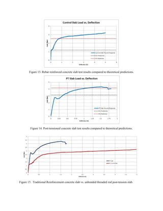
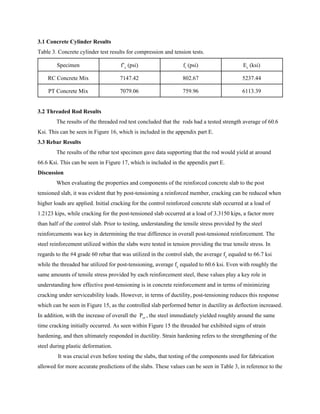
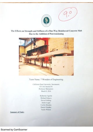
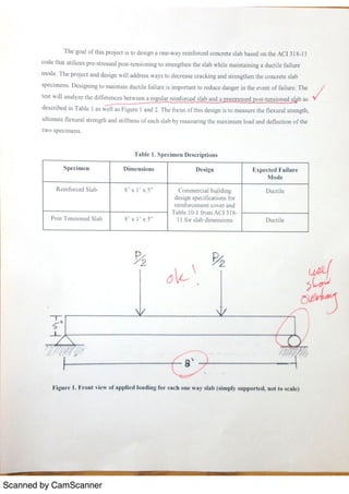
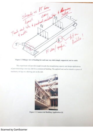
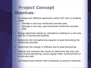
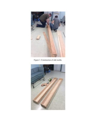
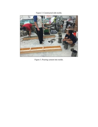
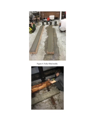
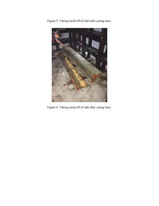
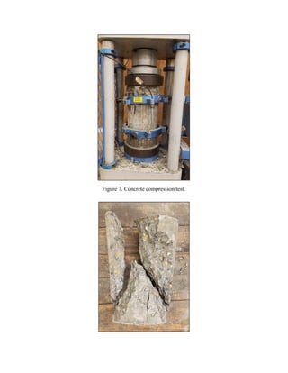
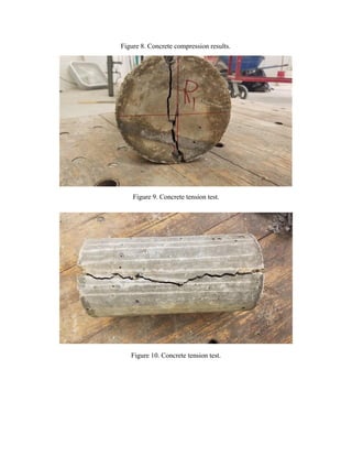
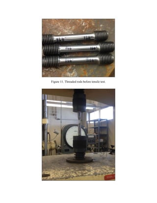
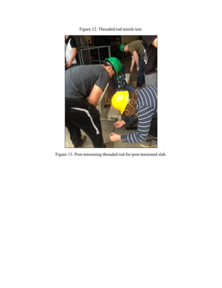
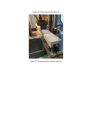
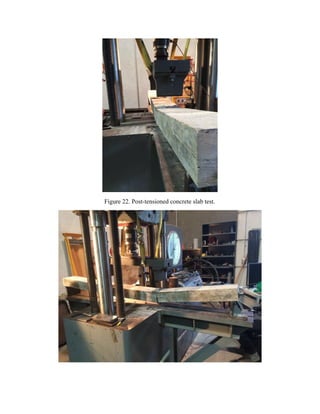
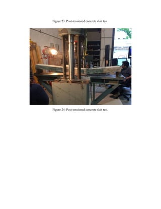
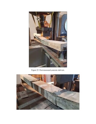
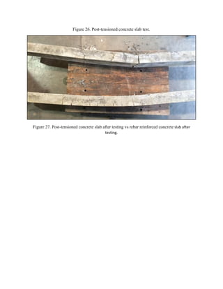
SlideShare a Scribd company logo
Comparison of Pre-Stressed/Post-Tensioned Reinforcement
to Traditional Steel Reinforcement
in Slabs in Order to Minimize Cracking
7 Wonders of Engineering
California State University, Sacramento
CE 164, Section 01
Professor Matsumoto
May 19, 2016
Katherine Aguilar
Michael Ednave
Devin Fielding
Justin Logan
Cecilia Morales
Daniel Oleshko
Taylor Wilson
Acknowledgements
7 Wonders of Engineering would like to thank the individuals and organizations for their
contributions and support that allowed the completion of this project. Key materials were donated by JJ
Rebar, Clark Pacific, Lowes and California State University, Sacramento Department of Civil
Engineering. For laboratory access, equipment, and testing assistance help we would like to thank
Michael Lucas, William Cope, and Jim Ster. For conceptual help and design recommendations, we would
like to thank Professor Matsumoto and Edwin J Nicholson.
Executive Summary
Reinforced concrete is prone to cracking under serviceability loads. When concrete cracks, the
moment of inertia decreases drastically and corrosion is introduced. A solution to these problems is the
process of prestress/post-tensioning. For this project, two slabs were tested in flexure: an unbonded
post-tension slab and a rebar reinforced concrete slab. The main objective for the project was to fabricate
and test the two slabs while utilizing similar tensile strengths; a #4 grade 60 rebar for rebar reinforcement
and ¾ inch threaded rod for post-tensioning. The threaded rod was post-tensioned to 17.266 kips in order
to increase the flexural moment required to induce cracking. By taking the equations from the ACI 318-11
building code requirements for structural concrete and by utilizing steel reinforcements with similar
tensile strengths, the benefits of a post tensioned slab can be seen in comparison to a rebar reinforced slab.
After the steel yielded in the rebar reinforced concrete slab, the slab performed as expected by
having a high ductile response. Ultimately, it failed in flexure as the cracks propagated all the way to the
top. In regards to the post-tensioned slab with the threaded bar, it was crucial to not over elongate the steel
as it would yield during the process. This can ultimately change the moment where cracking can occur. In
order to elongate the steel, hex nuts were applied to both ends and was tightened with a wrench and
measured with digital calipers. With this method, the steel was elongated to 0.175 inches which
maintained a small margin for error.
The results from this experiment showed that post-tensioning doubled the load before cracking,
(Pcr) and increased the ultimate strength by a factor of about 1.2. These results also showed that the
post-tensioned slab was able to withstand a higher load and flexural moment before cracking occurred.
The load required to crack the regular reinforced specimen was 1.200 kips while the post-tensioned
specimen resisted 3.135 kips before cracking. Also, after the initial cracking, the bar strain hardened,
enabling the slab to fail in flexure. However, compared to the reinforced concrete slab, the ductility
exhibited by the post-tensioned slab decreased by a factor of 3. In order to provide a better response
through post-tensioning, it is effective to increase the eccentricity by distancing the tensile force away
from the neutral axis. This can be done in practice by draping the post-tensioning strands so that the
eccentricity is not constant throughout the span.
From the results of this experiment, it is recommended to post-tension concrete slabs with the
intent to increase ultimate strength and reduce cracking at serviceability loads. Using the results from the
experiment, one can extrapolate specifications to design a one-way slab for the second floor of a hotel
building.
Table of Contents
Section Title Page #
Acknowledgements ii.
. Executive Summary iii.
1. Introduction 1
1.1 Background 1
1.2 Objectives 1
1.3 Theory and Key Equations 1
1.4 Outline 2
2. Approach 5
2.1 Concrete Cylinder and Slab Fabrication Procedure 6
2.2 Test Matrix 3
2.3 Cylinder Test Procedure 7
2.4 Steel Specimen Test Procedure
2.5 Slab Test Procedure 8
3.0 Results 10
3.1 Concrete Cylinder Results 13
3.2 Threaded Rod Results
3.3 Rebar Results
4.0 Discussion
5.0 Design Application 15
6.0 Conclusion
7.0 Recommendations
References iii.
Appendix iv.
A Original Project Proposal and Status Report
B PowerPoint Presentation Slides
C Presentation Handout
D Photos
E Figures
F Calculations
G Advice for Future Teams
Introduction
1.1 Background
Concrete is relatively strong in compression while weak in tension. The weakness of concrete in
tension can be compensated for by reinforcing the concrete with steel reinforcements (rebars, stirrups, or
prestressed cables). Reinforced concrete is widely used as a modern building material and is often used in
slabs, beams, foundations, walls and columns. Concrete is made by mixing a ratio of cement, water and
aggregates (coarse gravel and sands). This reinforced concrete is able to withstand high amounts of stress
due to its tensile and compressive strength, which are determined by aggregates, water content and cure
time.
A widely practiced form of reinforced concrete is prestressed post-tensioned concrete.
Post-tensioning is a form of prestressed concrete in which the prestressing tendons are stressed after the
concrete is cast. Prior to casting, the post-tensioning tendons are placed inside plastic ducts or sleeves and
are positioned into forms. Once the concrete has the adequate amount of time to gain the strength needed
to allow serviceable loads, the post-tensioned cables are then pulled and tensioned and anchored to the
outer edge of the concrete. By utilizing high tensile strength steel, Pre-Stressed/ Post-tensioning is able to
rid of the problems that comes along when using rebar and stirrups such as congestion while ultimately
performing as well or even better than regular reinforcements.
1.2 Objectives
The objective of the experiment was to design a prestressed post-tensioned slab to
minimize/eliminate concrete cracking under service loads compared to a rebar reinforced concrete slab,
while using the same tensile strength. This means what under daily use, the post-tensioning will keep the
concrete from cracking in the slab.
This main objective involved smaller objectives such as:
▪ To design two specimens within ACI 318-11 building codes.
− Develop a one-way, steel reinforced concrete slab.
− Develop a one-way, prestressed/post-tensioned steel reinforced concrete slab.
▪ Design specimens based on calculations relating to a one-way slab for a commercial
building.
▪ Determine the strengthening capacity of post-tensioning the reinforced concrete.
▪ Determine the change in stiffness due to post-tensioning.
▪ Analyze and compare the results to determine the pros and cons of post-tensioning versus
regular rebar reinforcement of a one-way slab.
▪ Correspond and interact with companies to procure materials.
1.3 Theory and Key Equations
There are main concepts and related equations that are needed to understand the principles
involved in regular reinforced concrete and post-tension reinforced concrete. Properties such as concrete
compressive strength, concrete splitting (tensile) strength, and reinforcement strength must all be known
and measured. In this experiment, an accurate measurement in reinforcement strength was crucial because
of the use of a threaded rod for post-tensioning rather than conventional 270 ksi strands. These
measurables give more accurate information to be used in the process of making predictions for the
specimens. It is valuable to know material properties to maintain proper expectations of reinforced
concrete structures in the real world.
The fabrication of concrete cylinders from each batch of concrete gives more measurable
certainty that the batches are approximately equal in strength. The simple experimental design of the slabs
allowed for a relatively low water to cement ratio which in turn led to a low slump. That allowed for a
high concrete strength to be achieved. It is also important to keep the cylinders in the same environment
as the slabs to ensure that they have equal curing. First, the process of determining compressive strength
is done by compressing the concrete cylinders until failure. By measuring the force required to break the
cylinders, we can determine that compressive strength (f’​c​). On one cylinder from each batch, a linear
variable differential transformer (LVDT) was used to measure the deformation of the cylinder as load was
applied. That measurement was used along with stress to determine the Modulus of Elasticity of the
concrete (E​c​). E​c​ is important for accurately transforming our section to make predictions based on the
modular ratio (E​s​/ (E​c​). The other concrete characteristic that was tested for was the splitting strength.
With the cylinder laid on its side, a force was distributed along the top edge. The force that causes the
cylinder to split down the middle was measured to determine the modulus of rupture (f​r​), which is
instrumental in determining our cracking moment.
The threaded rod for post-tensioning and the rebar used in this experiment underwent tensile tests.
This gave accurate measurements of the relative tensile strength, and most importantly, the yield strength
(f​y​) of each material. The testing was done by stretching each steel material to record the average
respective yield strengths. The yield strengths were used in determining nominal flexural strength (M​n​).
Also, in the case of the threaded rod, it was used to find the elongation (𝛿) needed to apply post-tension
force.
After finding the necessary material properties, predictions could be made for each slab specimen.
With the main goal of our experiment being to create a higher cracking moment by post-tensioning a slab,
the equations for properly stresing the threaded rod and the cracking moment of the specimens are of most
significance to this experiment.
Equation 1:​
Equation 1 is used to determine the elongation of the threaded rod needed to apply the necessary
post-tension force. Since the threaded rod is so weak compared to conventional post-tensioning strands, it
was stressed to 95% of yield strength in order to cause significant experimental results.
Equation 2:
Equation 2 is used to predict the cracking moment for the regular reinforced concrete specimen. The
cracking moment is the moment needed to cause cracking in the tension region of the slab. Below the
neutral axis, the concrete is in tension, the weakness of concrete. M​cr​ is calculated from attributes of the
concrete in a transformed section because until the concrete cracks, the steel reinforcement does not
provide a major reaction. For that reason, it is largely based off of the tensile strength of the concrete.
Equation 3:
Equation 3 is used to predict the cracking moment for the post-tensioned specimen. The cracking moment
includes support from the threaded rod as standard reinforcement and the post-tension effect. They are
added together to get the total moment required to cause cracking in the concrete. With the
prestress/post-tension effect, the concrete is subject to compression and upward bending. That way, the
concrete will not crack in tension until the applied loads create a moment that overcomes all of the
combined resistance.
Equation 4:
Equation 4 is used to determine the flexural strength of the regular reinforced concrete specimen. It is the
moment required to cause flexural failure in the specimen.
Equation 5:
Equation 5 is used to determine the flexural strength of the post-tensioned reinforced concrete specimen.
It is very similar to Equation 4, but it accounts for the applied unbonded prestress/post-tension effect.
Terms such as the approximated stress of the tensioned steel at failure (f​ps​), and the distance (a) of the
equivalent rectangular stress distribution both depend on the effective prestress applied.
Equation 6:
Equation 6 is used to determine the load required to induce a response relative to the predicted moment
(M) used. It is based on the symmetric third point loading configuration used in this experiment where l​1
is one third of the span of the specimen.
1.4 Outline
The following report will discuss the comparison of pre-stressed/post-tension reinforcement to
traditional steel reinforcement in slabs under service loads. The outline of the report is as followed:
I. Approach
II. Results
III. Discussion
IV. Design Application
V. Conclusion
VI. Recommendation
Approach
2.1 Concrete Cylinder and Slab Fabrication Procedure
I. Fabrication and preparation of slab forms
A. Pre-fabricate 2 slab molds according to desired specifications
B. Rebar Reinforced slab: Cut the rebar to the length of the mold
C. PT slab: Cut the threaded rod about 4 inches longer than the span of the mold while
cutting the PT sheath (PVC) to span the length of the slab
A. Place the rebar and threaded rod at 3 inches from the top so that both slabs would have
the same ​d values. This will also give proper cover for both the rebar and sheath covered
threaded rod.
D. Clean and lightly oil all molds to prevent sticking.
Figure 1. Slab molds after fabrication. Figure 2. Cylinder molds being oiled and prepped.
II. Concrete Mixing
A. Measure and weigh the required amount of cement, sand, and gravel with proportions of
1:2:3, respectively.
B. Estimate and weigh needed water to cement ratio (.48 w/c ratio was used)
C. Mix the sand and gravel, then add cement and mix thoroughly.
D. Slowly add part of the water, mix, add the rest of the water and mix again.
III. Pouring test specimens
A. Once the concrete is uniformly mixed, perform the ASTM C143 Slump test using a
representative sample from the batch.
B. Pour the cement into the molds and use the stinger to vibrate the cement to remove air
pockets and voids.
C. Screen the concrete to the top of the form and and trowel a smooth flat surface.
D. Place wet rags onto the concrete approximately 1.5 hours to retain moisture.
Figure 3. Slump Test Figure 4. Molds filled with concrete.
IV. The next morning, the specimens were placed in the moisture room. The cylinder specimens
were left to cure for 19 days, while the slab specimens were left to cure for 20 days.
2.2 Test Matrix
Table 1. This is the test matrix for the rebar reinforced and post-tensioned concrete slab specimens.
Test
Specimen
Dimensions
(w x h x l)
(in)
A​s
(in​2​
)
F​y
(ksi)
Tensile strength
(kips)
Expected Failure
Mode
PT 8 x 4.2 x 88 0.3 60.6 18.18 Flexural/
Concrete Crush
RC 8 x 4.2 x 88 0.2 66.7 13.34 Flexural
2.3 Cylinder Test Procedure
The cylinders were tested in two batches.
I. Tensile testing (Test Method C39/C 39M)
A. each cylinder was placed on its side and blocks were placed on
top of the cylinder until it came in contact with the testing
machine.
B. The load was then added until the cylinders were split.
II. Compressive strength Test.
A. A LVDT collar was attached to one cylinder from each batch that
was tested in compression.
B. Cap-plates were placed on the bottom and top of the cylinder to be
tested to prevent surface cracking.
C. The cylinders were loaded until failure.
2.4 Steel specimen Test Procedure
Steel reinforcement were tested for tensile strength accuracy.
I. Threaded Rod and Rebar Procedure Test
A. Place a sample of a material between two fixtures (grips)
B. Apply weight to the material gripped at one end while other end is fixed
C. A LVDT was placed to measure the elongation
2.5 Slab Test Procedure
Before testing, the post-tensioned slab was post-tensioned using nuts and a wrench.
The elongation of the threaded rod being tensioned was determined to be 0.175 in. Corresponding to an
added force of 17.266 kips
.
Figure 10. Post-tensioning of the threaded rod.
I. For both of the slab tests, the pin/roller supports were placed at a distance of 84 in. a part to
support each slab.
II. The beams were then loaded onto the Riehle Testing Machine.
III. A LVDT was placed at midspan to measure deflection while the loading force was also measured.
IV. A lab technician operated the machine and oversaw the test.
V. Cracks were marked
VI. Each slab was tested until failure or as close to failure as possible.
Figure 11. Post-tensioned beam. Figure 12. Rebar Reinforced Beam.
Results
The following section contains results from the various tests conducted. The results are displayed
in tabular and graphical form in this section. Table 3. evaluates the results of the cylinder compression
and tension tests of the six cylinders. Figures 13,14, and 15 show the rebar reinforced and post-tensioned
slab test load and deflection data. From the tests that were conducted for the rebar reinforced and
post-tensioned concrete slabs, a comparison to theoretical calculations is displayed in Table 2.
Table 2. Comparison of theoretical and experimental load values.
Test Specimen RC Comparable RC Unbonded PT
Load P​cr​ (kips) P​n​ (kips) P​cr​ (kips) P​n​ (kips) P​cr​ (kips) P​n​ (kips)
Theoretical 1.1999 2.5451 1.2123 3.4634 3.1350 4.1650
Experimental 1.1706 3.2198 - - 2.7734 4.3278
Figure 13. Rebar reinforced concrete slab test results compared to theoretical predictions.
.
Figure 14. Post-tensioned concrete slab test results compared to theoretical predictions.
Figure​ ​15. Traditional Reinforcement concrete slab vs. unbonded threaded rod post-tension slab.
3.1 Concrete Cylinder Results
Table 3. Concrete cylinder test results for compression and tension tests.
Specimen f’​c​ (psi) f​r​ (psi) E​c​ (ksi)
RC Concrete Mix 7147.42 802.67 5237.44
PT Concrete Mix 7079.06 759.96 6113.39
3.2 Threaded Rod Results
The results of the threaded rod test concluded that the rods had a tested strength average of 60.6
Ksi. This can be seen in Figure 16, which is included in the appendix part E.
3.3 Rebar Results
The results of the rebar test specimen gave data supporting that the rod would yield at around
66.6 Ksi. This can be seen in Figure 17, which is included in the appendix part E.
Discussion
When evaluating the properties and components of the reinforced concrete slab to the post
tensioned slab, it was evident that by post-tensioning a reinforced member, cracking can be reduced when
higher loads are applied. Initial cracking for the control reinforced concrete slab occurred at a load of
1.2123 kips, while cracking for the post-tensioned slab occurred at a load of 3.3150 kips, a factor more
than half of the control slab. Prior to testing, understanding the tensile stress provided by the steel
reinforcements was key in determining the true difference in overall post-tensioned reinforcement. The
steel reinforcement utilized within the slabs were tested in tension providing the true tensile stress. In
regards to the #4 grade 60 rebar that was utilized in the control slab, the average f​y​ equaled to 66.7 ksi
while the threaded bar utilized for post-tensioning, average f​y​ equaled to 60.6 ksi. Even with roughly the
same amounts of tensile stress provided by each reinforcement steel, these values play a key role in
understanding how effective post-tensioning is in concrete reinforcement and in terms of minimizing
cracking under serviceability loads. However, in terms of ductility, post-tensioning reduces this response
which can be seen in Figure 15, as the controlled slab performed better in ductility as deflection increased.
In addition, with the increase of overall the P​cr ​, the steel immediately yielded roughly around the same
time cracking initially occurred. As seen within Figure 15 the threaded bar exhibited signs of strain
hardening, and then ultimately responded in ductility. Strain hardening refers to the strengthening of the
steel during plastic deformation.
It was crucial even before testing the slabs, that testing of the components used for fabrication
allowed for more accurate predictions of the slabs. These values can be seen in Table 3, in reference to the
RC slab, there was only a 2.5% difference in the theoretical and experimental values of P​cr​. While the
difference for P​cr ​in the post-tensioned slab was 11.5%. This greater difference could have been caused
during the post-tensioning process of the slab, while elongating the threaded bar. By utilizing the yield
stress of the threaded bar, calculations determined that the threaded bar needed to be elongated by .175
inches. This elongation of the bar provided little to no room of error as it can ultimately change the
response and reinforcement of the slab. If the rod was not elongated enough, then the post-tensioning
would not provide adequate amount of reinforcement to the slab and can lower the load at which cracking
can occur. However, if the threaded bar was elongated greater than .175, the bar would ultimately yield.
This would ultimately change how the slab would perform while loads are being applied as the response
of the slab would remain stagnant and there would be no clear evidence on just how effective
post-tensioning is in reinforcement.
Design Application
In order to fully understand how the lessons above apply to the field, a one-way post-tensioned
(PT) slab was designed for hotel loading i.e. the second floor of a multi-story hotel. The design process
began with a set span length and was followed per ACI 318-14 to analyze the sufficiency of
post-tensioning on the ultimate strength capacity as compared to the strength demand under service
conditions. The main difference, when compared to design of a standard reinforced slab, is the uplift force
on the slab as an effect of PT compressive force on the concrete. This allows the slab to offset the effects
of a significant portion of service loads. Therefore, given the PT supplies enough uplift, the standard
reinforcement may be minimized. This entails that the remaining design calculations need only cover
minimum standard reinforcement and maximum spacing. So was the case for the one-way slab designed
for this report, and it is recommended that continuation of this project explore the minimum standard
reinforcement with a maximum spacing.
Conclusion
Fabrication and testing a rebar reinforced concrete slab and a post-tensioned reinforced concrete
slab provided insight toward various applications of reinforcement in concrete structures. To better
understand how each specimen will act under loading, it is beneficial to tensile test the strength of each
steel reinforcement. Knowing the actual strengths of the reinforcement will allow the designer to make
more accurate predictions on how the structure will act under different loads. The post-tensioned slab in
comparison to the control reinforced concrete slab was able to withstand more than 2 times the load and
moment before the concrete begin cracking in tension; a load of 3.13 kips to 1.21 kips respectively. The
results from this experiment provide evidence showing that the use of post-tensioning will increase the
allowable load before cracking and can ultimately eliminate cracking of slabs under service loads.
Because the concrete does not crack under serviceability loads, the concrete will deflect less than
traditional rebar reinforcement.There is also a reduced risk of steel corrosion with the elimination of
cracking with prestressing.
Recommendation
Prestressing Steel in Reinforced Concrete allows concrete to sustains higher loads before
cracking. Therefore, to eliminate cracking under serviceability loads, it is recommended to include
Prestressing forces in the design of concrete slabs. Because prestressing strands have less ductility,
limitation in anchoring and transferring moment into columns, it is also recommended to use a
combination of rebar and prestressing strands.
References
1. Kamara, M. and Novak, L. Editors. Notes on ACI 318-11 Building Code Requirements for
Structural Concrete. Portland Cement Association, Skokie, IL, 2011.
2. The Reinforced Concrete Design Handbook SP-17(14), One Way Slabs. 2015.
Appendix
A - Original Project Proposal and Status Report
B - PowerPoint Presentation Slides
C - Presentation Handout
D - Photos
E - Figures
F - Calculations
G - Advice for Future Teams
A.​ Original Project Proposal and Status Report
Scanned by CamScanner
PROJECT STATUS REPORT
PROJECT SUMMARY
Report Date Project Name Prepared By
April 1, 2016 The Effects and Stiffness of a One-Way
Reinforced Concrete Slab Due to Addition
of Post-Tensioning
7 Wonders of Engineering
STATUS SUMMARY
So far, Team 7 wonders of Engineering is a bit behind schedule in the Pour Day phase of this project. In order to prevent
further delay in project schedule, some adjustments to task assignments have been made.
The team has worked in contacting prospective sponsors for the Post-Tension strands, constructed frame work, and
started analyzing ADAPT-PT software. We are in hopes of being able to receive the post-tension strands by 4/1/16 from
Clark Pacific . We need to contact a company that would help us test the Post-tension slab with a hydraulic jack or look
for an alternative. Also, we are considering on switching to #5 rebar just to be comparable to the diameter of the
PT-Strand.
(See Action Item List below).
ACTION ITEMS
● ​Rescheduled
Task
% Done Due Date
Date
Completed
Assigned Comments
Data Gathering/Research
100 03/08/16 03/08/16 All
Re-submit Proposal
100 03/08/16 03/08/16 All
Contacting Sponsors
& Gathering Material 90 04/04/16 -
Taylor,
Devin,
Michael,
Cecilia
Rescheduled; Until we
receive PT strands.
Framework Calculations
100 03/17/16 03/17/16
Katherine,
Daniel
Framework Fabrication
100 03/17/16 03/18/16
Daniel,
Justin
Design calculations
Initiated 04/03/16 -
Katherine,
Taylor,
Cecilia
Pour Day
- 04/04/16 - All
ADAPT-PT Software
Application Initiated 05/02/16 -
Devin,
Michael,
Taylor,
Justin,
Cecilia
Testing Date
- 04/15/16 - All
Calculation Corrections
- 05/06/16 -
Devin,
Katherine,
Taylor
Report
- 05/17/16 - All
Presentation
- 05/17/16 - All
OUTSTANDING PROJECT ISSUES
Issue Concern Comments
Strengthen Time Going over scheduled
time.
Team 7 wonders of Engineering would like to
communicate an alternative of switching to cement
type 3 to reduced waiting time.
Equipment
We need a hydraulic
Jack to test
Post-tension slab
Team 7 Wonders of Engineering is contacting
companies to help us test Post tension slab or
looking for an alternative
Page 2
B. ​PowerPoint Presentation Slides
Project Status
The Effects and Stiffness of a One-Way
Reinforced Concrete Slab Due to Addition of
Post-Tensioning
By: 7 Wonders of Engineering
Status Summary
▪ On Track
▪ Rescheduled
− Pour Day
− Test Day
Project Concept
Objectives:
▪ To design two different specimens within ACI 318-11 building
codes.
− Develop a one-way reinforced concrete slab.
− Develop a one-way, post-tensioned reinforced concrete
slab.
▪ Design specimens based on calculations relating to a one-way
slab for a commercial building.
▪ Determine the strengthening capacity of post-tensioning the
reinforced concrete.
▪ Determine the change in stiffness due to post-tensioning.
▪ Analyze and compare the results to determine the pros and
cons of post-tensioning versus regular rebar reinforcement of
a one-way slab.
▪ Correspond and interact with companies to procure materials.
Progress
▪ Resubmit Proposal by omitting Steel
Fibers
▪ Framework Fabrication
Progress
▪ Gather Material to be
ready for Pour Day
(April 4,2016)
▪ Calculations for
water/cement Ratio,
rebar & PT-Strand
Placement are in
progress
Attention Areas
▪ Find a sponsor for Post-Tension
Strands & gather material
▪ Solutions:
− Contact more companies for help
− Reschedule Pour Day & Test Day
− Considering changing Type of cement
for shorter waiting time
Schedule
Task % Done Due Date
Date
Completed
Assigne
d
Comments
Data Gathering/Research
100 03/08/16 03/08/16 All
Resubmit Proposal
100 03/08/16 03/08/16 All
Contacting Sponsors
& Gathering Material 90 04/04/16 -
Taylor,
Devin,
Michael,
Cecilia
Rescheduled; Until we receive
PT strands.
Framework Calculations
100 03/17/16 03/17/16
Katherin
e, Daniel
Framework Fabrication
100 03/17/16 03/18/16
Daniel,
Justin
Design calculations
Initiated 04/03/16 -
Katherin
e,
Taylor,
Cecilia
Pour Day
- 04/04/16 - All
ADAPT-PT Software
Application Initiated 05/02/16 -
Devin,
Michael,
Taylor,
Justin,
Cecilia
Testing Date
- 04/15/16 - All
Calculation Corrections
- 05/06/16 -
Devin,
Katherin
e, Taylor
Report
- 05/17/16 - All
Presentation
- 05/17/16 - All
List of Goals:
▪ Obtain Post-tension Strands in order
to Fabricate Slabs
▪ Continue with real life application
using ADAPT-PT software
▪ Try to stay on schedule for future
datelines
C.​ Presentation Handout
D​. Photos
Figure 1. Construction of slab molds.
Figure 2. Constructed slab molds.
Figure 3. Pouring cement into molds.
Figure 4. Fully filled molds.
Figure 5. Taking mold off of slab after curing time.
Figure 6. Taking mold off of slab after curing time.
Figure 7. Concrete compression test.
Figure 8. Concrete compression results.
Figure 9. Concrete tension test.
Figure 10. Concrete tension test.
Figure 11. Threaded rods before tensile test.
Figure 12. Threaded rod tensile test.
Figure 13. Post-tensioning threaded rod for post-tensioned slab.
Figure 14. Post-tensioning threaded rod for post-tensioned slab.
Figure 15. Post-tensioning threaded rod for post-tensioned slab.
Figure 16. Post-tensioning threaded rod for post-tensioned slab.
Figure 17. Post-tensioning threaded rod for post-tensioned slab.
Figure 18. Rebar reinforced slab test.
Figure 19. Rebar reinforced slab test.
Figure 20. Rebar reinforced slab test.
Figure 21. Post-tensioned concrete slab test.
Figure 22. Post-tensioned concrete slab test.
Figure 23. Post-tensioned concrete slab test.
Figure 24. Post-tensioned concrete slab test.
Figure 25. Post-tensioned concrete slab test.
Figure 26. Post-tensioned concrete slab test.
Figure 27. Post-tensioned concrete slab after testing vs rebar reinforced concrete​ slab after
testing.
E​. Figures
Figure 16. Threaded Rod Tensile Results
Figure 17. Rebar Tensile Results
Figure 18. Cylinder Test
Figure 19.Beam Loading and testing conditions.
F​. Calculations
CALIFORNIA STATE UNIVERSITY, SACRAMENTO
DEPARTMENT OF CIVIL ENGINEERING
CE164, REINFORCED CONCRETE DESIGN
Experimental Pretest Prediction Calculations
7 Wonders of Engineering
Katherine Aguilar
Michael Ednave
Devin Fielding
Justin Logan
Cecilia Morales
Daniel Oleshko
Taylor Wilson
Professor Matsumoto
May 17, 2016
1. The following calculations are for the purpose of making pretest predictions for the
post-tensioned and reinforced concrete slab experimental specimens. These calculations
further understanding of the effects of post-tensioned reinforcement and its benefits. The
reason for applying post-tension force is to decrease cracking of the concrete at service
level. Another benefit is a higher maximum capacity than traditional reinforced concrete.
The main concepts involved are finding the cracking moment (M​cr​) and the flexural
strength (M​n​). These two values for each specimen numerically and qualitatively show
change in strength due to post-tensioning. The cracking moment is most important to this
topic, as decreasing or removing cracking at service level is the primary purpose of
post-tension reinforced concrete. Through finding predictions for cracking moment and
flexural strength for our specimens, the magnitude can be seen of how post-tension forces
increase strength. However, it is important to note that rather than a conventional 270 ksi
strand, a 60 ksi threaded rod was used. This means that the applied force through
post-tensioning is minimal compared to real world applications. Still, the effects of
post-tensioning are to be seen even with the use of lower strength steel.
The calculations will begin with finding M​cr​ and M​n​ for the post-tensioned slab so that the
corresponding load forces P​cr​ and P​n​ (which are specific to our load combination) can be
found. Since we will be testing while measuring load and deflection, the load values are
essential to relating strength to moments. In order to find M​cr​ for the post-tension slab, the
applied post-tension force was needed. From that, it was found how much elongation of
the threaded rod would be necessary to apply that force to the slab. This was based on the
average yield strength of the threaded rod from testing. Characteristics of the concrete
such as compressive strength and modulus of rupture were also found in order to increase
the accuracy of predictions. Then, through transforming the section, the cracking moment
was found. The cracking moment for the post-tension slab includes the cracking moment
that would exist if only the rod was used for reinforcement without tensioning, and the
effects of tensioning the rod. This led to the finding of the cracking load force (P​cr​) based
on a third point loading configuration. Similarly, the ultimate moment was found from
the combination of the regular reinforcement of the rod being in place and the applied
post-tensioning. That was used to find the ultimate load force (P​n​) using the same third
point loading configuration.
Similar processes were conducted for the regular reinforced concrete slab. Characteristics
of the concrete were found in the same way, as well as the average yield strength of the
reinforcing steel which was #4, Grade 60 rebar. Again, through transforming the section,
the cracking moment was found. The regular reinforced concrete slab only relies on the
basic reinforcement of the rebar. With that, the predicted ultimate moment was found.
The loads P​cr​ and P​n​ were found for the regular reinforced concrete slab using the same
third point loading as the post-tension slab, but with the corresponding moments. The
same processes were used for a theoretical (non-experimental) RC slab that has the same
tensile strength in steel reinforcement as the PT slab. It allows for a closer comparison on
the effects of post-tensioning in this experiment. However, because the amount and
strength of steel does not majorly change the cracking moment, the main concern of
increasing the cracking moment with post-tension forces remains valid.
Post-tensioned (PT) Slab:
Slab Dimensions:
Base (b), inches 8
Height (h), inches 4.2
Effective Depth (d), inches 3
Span Length (l), inches 84
Total Length (L), inches 88
Slab Properties:
Modulus of Elasticity of Steel (E​s​), ksi 29,000
Diameter of Threaded Rod (d​b​), inches 0.75
Area of Threaded Rod (A​ps​), squared inches 0.3
Yield Strength of Threaded Rod (f​y​), ksi 60.5810
Post-tensioned Force (P​pt​), kips 17.2656
Eccentricity (e), inches 0.9
Cylinders Properties:
Diameter (d), inches 6
Length (l), inches 12
Concrete compression strength (f’c), psi 7079
Concrete Tension Test Force (P​t​), pounds
1. Threaded rod test, fy:
The average yield strength of the threaded rod was calculated from the three test samples.
a. )fy = ( 3
f +f +fy1 y2 y3
b. )fy = ( 3
58.74741ksi+61.68213ksi+61.31322ksi
c. 0.58102 ksify = 6
2. Post-tensioned force, P​pt.​:
The post-tension force that will be applied to the slab is an attempt to get as much force
as possible without yielding the steel. For that reason, the threaded rod is tightened to
0.95f​y​.
a. .95Ppt = 0 * fy * Aps
b. .95 0.58102 .3in.Ppt = 0 * 6 in.2
kips
* 0 2
c. = 17.2656 kipsPpt
3. Elongation, :δ
The elongation of the threaded rod needed to apply force P​pt​ to the slab is determined.
The number is rounded to three decimal places because our measuring device while
tightening the threaded rod measures to three decimals.
a. = 0.95*δ = AE
PL
fy * E
L
b. .95 0.58102ksiδ = 0 * 6 *
88in.
29000 ksi
c. .1746in. 0.175in.δ = 0 ˜
4. Concrete Compression Strength, f’​c​:
Based on the concrete cylinder compression tests, the average force at failure is
determined. Then that value is used to find the compressive strength of the concrete.
a. Pcavg. = 2
P +Pc1 c2
b. Pcavg. = 2
196900lb +203411.7lbf f
c. 00, 55.85lbPcavg. = 2 1 f
d. Area = A r (3 ) 8.27433in.c = π 2 = π 2
= 2 2
e. f′c = Ac
pcavg.
f. f′c = 28.2743 in.2
200,155.85lbf
g. 079.07psif′
c = 7
5. Splitting Tensile Strength, T:
From the concrete tensile test where the cylinder was split, the splitting tensile strength is
calculated.
a. T =
2 P* t
π l d* *
b. T = 2(57,300lbs.)
π (12in.)(6in.)*
c. 06.6432psiT = 5
6. Modulus of rupture, f​r​:
In relation to splitting tensile strength of the concrete, the modulus of rupture of the
concrete is found.
a. .5Tfr = 1
b. .5(506.6432psi)fr = 1
c. 59.9649psifr = 7
7. Cracking moment, M​cr​:
The cracking moment includes support from the threaded rod as standard reinforcement (
and the post-tension effect ( . They are added together to get the total)yt
f Ir* tr
( ))Ppt
Itr
A yc t
+ e
moment required to cause cracking in the concrete. With standard reinforcement and the
given loading configuration, the concrete below the neutral axis would be in tension.
However, with the prestress/post-tension effect, the concrete is subject to compression
and upward bending. That way, the concrete will not crack in tension until the loads
create a moment that overcomes all of the resistance.
a. ( )Mcr = yt
f Ir* tr
+ Ppt
Itr
A yc t
+ e
i. The calculation of n relates the elastic modulus of steel to the elastic
modulus of the concrete. The ratio is used to transform the steel into an
equal concrete section. = = 4.7437n = Es
Ec
29000ksi
6113.39 ksi
ii. The calculation for distance c​tr​|​top​ is finding the neutral axis of the
transformed section from the top of the section.
c​tr​|​top​ == ∑ Ai
A hi* i
bh+(n−1)Aps
bh +(n−1)A d*2
h
ps*
1. c​tr​|​top = (8in.)(4.2in)+(4.7437−1)(0.3in. )2
(8in.)(4.2In).( )+(4.7437−1) 0.3in. 3in.2
4.2in.
*
2
*
2. c​tr​|​top​ = 2.1291 in.
iii. y​t​ is the distance from the bottom of the section to c​tr​|​top​.
= 4.2in. – 2.1291in. = 2.0709in.yt = h − ctr
iv. I​tr​ is the area moment of inertia about the neutral axis of the transformed
section.
I​tr​ n )A (d )= 3
b c* tr
3
+ 3
b y* t
3
+ 0 + ( − 1 ps − ctr
2
1. I​tr ​=
0 4.7437 )(0.3in. )(3in. .1291in.)3
(8in.) (2.1291in.)*
3
+ 3
(8in.) (2.0709in.)*
3
+ [ + ( − 1 2
− 2 2
2. I​tr ​= 50.27229in.4
b. M​cr ​= +17,265.6lbs. [2.07089in.
(759.9649psi)(50.27229in. )4
.9in(50.27229in.4)
(2.07089in.)(8in.)(4.2in.) + 0
c. M​cr =​ 46461.95 kips-in. = 3.8719 kips-ft.
8. Cracking force, P​cr ​:
The cracking force is based off of the third point loading configuration where .Mcr = 2
P lcr 1
The equation is rearranged to solve for P​cr​.
a. Pcr = l1
2 M* cr
b. Pcr = 28in.( )1ft.
12in.
2(3.8719kips−ft.)
c. 3.3187 kipsPcr =
i. Adjustment for self-weight:
Additionally, the maximum moment due to self-weight of the slab is
found. That maximum moment occurs at the mid-span due to the uniform
load. Since the maximum moment due to third point loading can also be
found at the mid-span, the moment due to self-weight can be subtracted
from the cracking moment to find the actual applied load necessary to
induce cracking.
1. W​sw ​ = γrc * b * h = γrc * Ac
2. W​sw ​ = (150 )(8in.*4.2in.)( = 35ft.
lbs.
)1ft.
12in.
2
ft.
lbs.
3. M​sw ​ = = = 214.375 lb-ft. = 0.21437 k-ft.8
w Lsw*
2
8
35 (84in. )ft.
lbs.
* *
1ft.
12in
2
d. P​cr ​ = = = 3.1350 kipsl1
2(M −M )cr sw
28in.( )1ft.
12in.
2(3.81719k−ft. −0.2144 k−ft.
9. Nominal Flexural Strength, M​n ​:
To find M​n​, it is first needed to find the effective prestress (f​pe​), prestressed reinforcement
ratio (ρ​p​), stress at failure (f​ps​), and the distance (a) of the equivalent rectangular stress
distribution. With these accounted for, the nominal flexural strength includes the effect of
the unbonded, post-tensioned forces. Similar to the cracking moment, the
prestress/post-tension effect much be overcome as well as the regular reinforcement
resistance.
i. 0, 00fps = fpe + 1 0 + f′c
100ρp
1. 7.552 ksifpe =
ppt
Aps
= 0.3in.2
17.2656 kips
= 5
2. =ρp = bd
Aps
.01250.3in.2
(8in.)(3in.) = 0
ii. = 73215.247psi =73.215ksi7.522 ksi 0, 00fps = 5 + 1 0 + 100(0.0125)
7079.065 psi
iii. .4563in.a =
A fps* ps
0.85 f b* ′c*
= o.3in 73215.252psi2
*
0.85 7079.065psi 8in.* *
= 0
a. M​n ​ = (d )Aps * fps − 2
a
b. 3215.252psi(3in. )Mn = 0.3in.2
* 7 − 2
0.4563in.
c. 0882.65lb n. .0736k t.Mn = 6 − i = 5 − f
10. Maximum force applied, P​n ​:
The maximum force is based off of the third point loading configuration where .Mn = 2
P ln 1
The equation is rearranged to solve for P​n​.
a. .1650 kipsPn = L1
2Mn
= (28in.)( )1ft.
12in.
2(5.0736k−ft.)
= 4
b. Adjustment for self-weight:
The same process is done to include self-weight of the slab as was done for the
cracking force.
=4.1650 kipsPn = L1
2Mn
= (28in.)( )1ft.
12in.
2(5.0736k−ft. −0.2144k−ft.)
Reinforced Concrete (RC) Slab:
1. Rebar test, f​y​:
The average yield strength of the rebar was calculated from the three test samples.
a. )fy = ( 3
f +f +fy1 y2 y3
b. 6727.29psify = 3
65,517.07psi+65,950.08psi+69714.72psi
= 6
c. 6727.29psify = 6
2. Concrete Compression Strength, f’​c​:
Based on the concrete cylinder compression tests, the average force at failure is
determined. Then that value is used to find the compressive strength of the concrete.
a. Pcavg. = 2
P +Pc1 c2
b. Pcavg. = 2
194900lbs.+209277.3lbs
c. 02.088.65lbsPcavg. = 2
d. Area = A r (3 ) 8.27433in.c = π 2 = π 2
= 2 2
e. f′c = Ac
pcavg.
f. f′c = 28.27433in.2
202.08865lbs.
g. 147.424psif′c = 7
3. Splitting Tensile Strength, T:
From the concrete tensile test where the cylinder was split, the splitting tensile
strength is calculated.
a. T =
2 P* t
π l d* *
b. T = 2(60,520lbs.)
π (12in.)(6in.)*
c. 35.1143psiT = 5
4. Modulus of rupture:
In relation to splitting tensile strength of the concrete, the modulus of rupture of the
concrete is found.
a. .5Tfr = 1
b. .5(535.1143psi)fr = 1
c. 02.6714psifr = 8
5. Cracking moment, M​cr​:
The cracking moment is the moment needed to cause cracking in the tension region of
the slab. Below the neutral axis, the concrete is in tension, the weakness of concrete.
M​cr​ is calculated from attributes of the concrete in a transformed section because until
the concrete cracks, the steel reinforcement is not exhibiting any major reaction.
a. Mcr = yt
f Ir* tr
i. The calculation of n relates the elastic modulus of steel to the elastic
modulus of the concrete. The ratio is used to transform the steel into an
equal concrete section. = = 5.5371n = Es
Ec
29000ksi
5237.44 ksi
ii. The calculation for distance c​tr​|​top​ is finding the neutral axis of the
transformed section from the top of the section.
c​tr​|​top​ ​= =∑ Ai
A hi* i
bh+(n−1)As
bh +(n−1)A d*2
h
s*
1. c​tr​|​top​ ​= (8in.)(4.2in)+(5.5371−1)(0.2in. )2
(8in.)(4.2In).( )+(5.5371−1) 0.2in. 3in.2
4.2in.
*
2
*
2. c​tr​|​top​ ​= 2.1237 in.
iii. y​t​ is the distance from the bottom of the section to c​tr​|​top​.
= 4.2in. – 2.1237in. = 2.0763in.yt = h − ctr
iv. I​tr​ is the area moment of inertia about the neutral axis of the
transformed section.
I​tr= n )A (d )3
b c* tr
3
+ 3
b y* t
3
+ 0 + ( − 1 s − ctr
2
1. I​tr ​=
0 5.5371 )(0.2in. )(3in. .1237in.)3
(8in.) (2.1237in.)*
3
+ 3
(8in.) (2.0763in.)*
3
+ [ + ( − 1 2
− 2 2
2. I​tr ​= 50.1077in.4
b. M​cr ​= 2.0763in.
(802.6714psi)(50.1077in. )4
c. M​cr =​ 19371.01 kips-in. =1.6142 kips-ft.
11. Cracking force, P​cr ​:
The cracking force is based off of the third point loading configuration where .Mcr = 2
P lcr 1
The equation is rearranged to solve for P​cr​.
a. Pcr = l1
2 M* cr
b. Pcr = 28in.( )1ft.
12in.
2(1.6142kips−ft.)
c. 1.3836 kipsPcr =
i. Adjustment for self-weight:
The same process is done to include self-weight of the slab as was done
for the cracking force of the PT slab.
1. W​sw ​ = γrc * b * h = γrc * Ac
2. W​sw ​ = (150 )(8in.*4.2in.)( = 35ft.
lbs.
)1ft.
12in.
2
ft.
lbs.
3. M​sw ​ = = = 214.375 lb-ft. = 0.21437 k-ft.8
w Lsw*
2
8
35 (84in. )ft.
lbs.
* *
1ft.
12in
2
d. P​cr ​ = = = 1.1999 kipsl1
2(M −M )cr sw
28in.( )1ft.
12in.
2(1.6142k−ft. −0.2144 k−ft.
12. Nominal Flexural Strength, M​n ​:
The nominal flexural strength is the maximum moment that the slab can handle before
failure in flexure. First, the distance of the equivalent rectangular stress block (a) is
needed.
i. .2746in.a =
A fs* y
0.85 f b* ′c*
= o.2in 66727.29psi2
*
0.85 7147.424psi 8in.* *
= 0
d. ​ =Mn (d )As * fy − 2
a
e. 6, 27.29psi(3in. )Mn = 0.2in.2
* 6 7 − 2
0.2746in.
f. 8204.04lb n. .1837k t.Mn = 3 − i = 3 − f
13. Maximum force applied, P​n​:
The maximum force is based off of the third point loading configuration where .Mn = 2
P ln 1
The equation is rearranged to solve for P​n​.
a. .7289 kipsPn = L1
2Mn
= (28in.)( )1ft.
12in.
2(3.1837k−ft.)
= 2
b. Including self-weight:
The same process is done to include self-weight of the slab as was done for the
cracking force of the PT slab.
=2.5451 kipsPn = L1
2Mn
= (28in.)( )1ft.
12in.
2(3.1837k−ft. −0.21446k−ft.)
RC Comparable Slab:
The RC Comparable Slab is one not tested in this experiment. It is identical to the RC
slab in every way except that the area of the rebar is a theoretical 0.272 in​2​
. That is
between the sizes of #4 and #5 rebar which have areas of 0.2 in​2​
and 0.31 in​2​
,
respectively. Since that size reinforcement is not made, it could not be experimentally
tested. The purpose of these calculations is to see the difference between them and
predictions for the PT slab. The area of 0.272 in​2​
is important because it gives an A​s​f​y
approximately equal to the A​ps​f​y​ from the PT slab.
A​s​f​y​ = .272in 6.727ksi 8.149 kips0 2
* 6 = 1
A​ps​f​y​ = .3in 0.581ksi 8.174 kips0 2
* 6 = 1
6. Cracking moment, M​cr​:
a. Mcr = yt
f Ir* tr
i. = = 5.5371n = Es
Ec
29000ksi
5237.44 ksi
ii. c​tr​|​top​ ​= =∑ Ai
A hi* i
bh+(n−1)As
bh +(n−1)A d*2
h
s*
1. c​tr​|​top​ ​= (8in.)(4.2in)+(5.5371−1)(0.272in. )2
(8in.)(4.2In).( )+(5.5371−1) 0.272in. 3in.2
4.2in.
*
2
*
2. c​tr​|​top​ ​= 2.1319 in.
iii. = 4.2in. – 2.1319in. = 2.0681in.yt = h − ctr
iv. I​tr= n )A (d )3
b c* tr
3
+ 3
b y* t
3
+ 0 + ( − 1 s − ctr
2
1. I​tr ​=
0 5.5371 )(0.272in. )(3in. .1319in.)3
(8in.) (2.1319in.)*
3
+ 3
(8in.) (2.1319in.)*
3
+ [ + ( − 1 2
− 2 2
2. I​tr ​= 50.3562in.4
b. M​cr ​= 2.0681in.
(802.6714psi)(50.3562in. )4
c. M​cr =​ 19544.11 kips-in. =1.6287 kips-ft.
14. Cracking force, P​cr ​:
a. Pcr = l1
2 M* cr
b. Pcr = 28in.( )1ft.
12in.
2(1.6287kips−ft.)
c. 1.3960 kipsPcr =
1. Adjustment for self-weight:
W​sw ​ = γrc * b * h = γrc * Ac
2. W​sw ​ = (150 )(8in.*4.2in.)( = 35ft.
lbs.
)1ft.
12in.
2
ft.
lbs.
3. M​sw ​ = = = 214.375 lb-ft. = 0.21437 k-ft.8
w Lsw*
2
8
35 (84in. )ft.
lbs.
* *
1ft.
12in
2
d. P​cr ​ = = = 1.2123 kipsl1
2(M −M )cr sw
28in.( )1ft.
12in.
2(1.6287k−ft. −0.2144 k−ft.
15. Nominal Flexural Strength, M​n ​:
i. .3734in.a =
A fs* y
0.85 f b* ′c*
= o.272in 66727.29psi2
*
0.85 7147.424psi 8in.* *
= 0
g. ​ =Mn (d )As * fy − 2
a
h. 6, 27.29psi(3in. )Mn = 0.272in.2
* 6 7 − 2
0.3734in.
i. 1060.59lb n. .2550k t.Mn = 5 − i = 4 − f
16. Maximum force applied, P​n​:
a. .6472 kipsPn = L1
2Mn
= (28in.)( )1ft.
12in.
2(4.2550k−ft.)
= 3
b. Including self-weight:
= 3.4634 kipsPn = L1
2Mn
= (28in.)( )1ft.
12in.
2(4.2550k−ft. −0.21446k−ft.)
Advice for Future Teams
We advise any groups pursuing this subject to really nail down what they want to test for early on
as it can save a lot of time. We also advise that you don’t overestimate how hard it will be to post-tension
your threaded rod because if you do it correctly, it will be very tough, so if you are able to get a
post-tensioning strand form a company and get them to post tension it for you, that would be nice and
easy for you. Lastly, it is also important to get materials early on and to fabricate as soon as possible
because life gets crazy when finals come around and you really don’t want to be working on this a lot
during finals week.

More Related Content

What's hot

Finite element analysis of jacketed reinforced concrete column subjected to u...
Finite element analysis of jacketed reinforced concrete column subjected to u...Finite element analysis of jacketed reinforced concrete column subjected to u...
Finite element analysis of jacketed reinforced concrete column subjected to u...
eSAT Publishing House
 
Ce572 introductiontoprestressing1
Ce572 introductiontoprestressing1Ce572 introductiontoprestressing1
Ce572 introductiontoprestressing1
Prateek Choudhary
 
Precast pretensioned concrete girders
Precast pretensioned concrete girdersPrecast pretensioned concrete girders
Precast pretensioned concrete girders
MD.Yeasin Mostafiz
 
2 marks Question with Answer for Design of Reinforced Cement Concrete Elements
2 marks Question with Answer for Design of Reinforced Cement Concrete Elements 2 marks Question with Answer for Design of Reinforced Cement Concrete Elements
2 marks Question with Answer for Design of Reinforced Cement Concrete Elements
shielaBalanta2
 
Design of rcc structures
Design of rcc structuresDesign of rcc structures
Design of rcc structures
R VIJAYAKUMAR
 
Lecture - 01: Introduction to Reinforced Concrete Design
Lecture - 01: Introduction to Reinforced Concrete DesignLecture - 01: Introduction to Reinforced Concrete Design
Lecture - 01: Introduction to Reinforced Concrete Design
Hezb
 
Pre stressed concrete construction
Pre stressed concrete constructionPre stressed concrete construction
Pre stressed concrete construction
JenilPatel22
 
Pre stressed concrete Bridge
Pre stressed concrete BridgePre stressed concrete Bridge
Pre stressed concrete Bridge
Shubham Das
 
Prestressed pipes,tanks,poles
Prestressed pipes,tanks,polesPrestressed pipes,tanks,poles
Prestressed pipes,tanks,poles
PraveenKumar Shanmugam
 
Civil Engineering : Rcc & steel structures, THE GATE ACADEMY
Civil Engineering : Rcc & steel structures, THE GATE ACADEMYCivil Engineering : Rcc & steel structures, THE GATE ACADEMY
Civil Engineering : Rcc & steel structures, THE GATE ACADEMY
klirantga
 
Methods of rcc design
Methods of rcc designMethods of rcc design
Methods of rcc design
Selvakumar Palanisamy
 
Flexure Behaviour of Ferrocement Strengthened RC beams
Flexure Behaviour of Ferrocement Strengthened RC beamsFlexure Behaviour of Ferrocement Strengthened RC beams
Flexure Behaviour of Ferrocement Strengthened RC beams
IEI GSC
 
Presentation
PresentationPresentation
Presentation
Alauddin Khan
 
Steve Gregan -The Fatigue Performance Assessment of Corrosion Damaged RC Beam...
Steve Gregan -The Fatigue Performance Assessment of Corrosion Damaged RC Beam...Steve Gregan -The Fatigue Performance Assessment of Corrosion Damaged RC Beam...
Steve Gregan -The Fatigue Performance Assessment of Corrosion Damaged RC Beam...Steve Gregan
 
Design and Detailing of RC structures
Design and Detailing of RC structuresDesign and Detailing of RC structures
Design and Detailing of RC structures
gssnie
 
Comparison of reinforced concrete and prestressed concrete
Comparison of reinforced concrete and prestressed concreteComparison of reinforced concrete and prestressed concrete
Comparison of reinforced concrete and prestressed concrete
Spice Shuvo
 
Reinforcement concrete and properties of matrial
Reinforcement concrete and properties of matrial Reinforcement concrete and properties of matrial
Reinforcement concrete and properties of matrial
VIKAS4210607
 
STRENGTHENING OF RC BEAMS USING FRP SHEET
STRENGTHENING OF RC BEAMS USING FRP SHEETSTRENGTHENING OF RC BEAMS USING FRP SHEET
STRENGTHENING OF RC BEAMS USING FRP SHEET
Ijripublishers Ijri
 
Prestressed concrete circular storage tanks
Prestressed concrete circular storage tanksPrestressed concrete circular storage tanks
Prestressed concrete circular storage tanks
Aman Bagrecha
 
External Prestressing of Concrete Members
External Prestressing of Concrete MembersExternal Prestressing of Concrete Members
External Prestressing of Concrete Members
Praveen S.K
 

What's hot (20)

Finite element analysis of jacketed reinforced concrete column subjected to u...
Finite element analysis of jacketed reinforced concrete column subjected to u...Finite element analysis of jacketed reinforced concrete column subjected to u...
Finite element analysis of jacketed reinforced concrete column subjected to u...
 
Ce572 introductiontoprestressing1
Ce572 introductiontoprestressing1Ce572 introductiontoprestressing1
Ce572 introductiontoprestressing1
 
Precast pretensioned concrete girders
Precast pretensioned concrete girdersPrecast pretensioned concrete girders
Precast pretensioned concrete girders
 
2 marks Question with Answer for Design of Reinforced Cement Concrete Elements
2 marks Question with Answer for Design of Reinforced Cement Concrete Elements 2 marks Question with Answer for Design of Reinforced Cement Concrete Elements
2 marks Question with Answer for Design of Reinforced Cement Concrete Elements
 
Design of rcc structures
Design of rcc structuresDesign of rcc structures
Design of rcc structures
 
Lecture - 01: Introduction to Reinforced Concrete Design
Lecture - 01: Introduction to Reinforced Concrete DesignLecture - 01: Introduction to Reinforced Concrete Design
Lecture - 01: Introduction to Reinforced Concrete Design
 
Pre stressed concrete construction
Pre stressed concrete constructionPre stressed concrete construction
Pre stressed concrete construction
 
Pre stressed concrete Bridge
Pre stressed concrete BridgePre stressed concrete Bridge
Pre stressed concrete Bridge
 
Prestressed pipes,tanks,poles
Prestressed pipes,tanks,polesPrestressed pipes,tanks,poles
Prestressed pipes,tanks,poles
 
Civil Engineering : Rcc & steel structures, THE GATE ACADEMY
Civil Engineering : Rcc & steel structures, THE GATE ACADEMYCivil Engineering : Rcc & steel structures, THE GATE ACADEMY
Civil Engineering : Rcc & steel structures, THE GATE ACADEMY
 
Methods of rcc design
Methods of rcc designMethods of rcc design
Methods of rcc design
 
Flexure Behaviour of Ferrocement Strengthened RC beams
Flexure Behaviour of Ferrocement Strengthened RC beamsFlexure Behaviour of Ferrocement Strengthened RC beams
Flexure Behaviour of Ferrocement Strengthened RC beams
 
Presentation
PresentationPresentation
Presentation
 
Steve Gregan -The Fatigue Performance Assessment of Corrosion Damaged RC Beam...
Steve Gregan -The Fatigue Performance Assessment of Corrosion Damaged RC Beam...Steve Gregan -The Fatigue Performance Assessment of Corrosion Damaged RC Beam...
Steve Gregan -The Fatigue Performance Assessment of Corrosion Damaged RC Beam...
 
Design and Detailing of RC structures
Design and Detailing of RC structuresDesign and Detailing of RC structures
Design and Detailing of RC structures
 
Comparison of reinforced concrete and prestressed concrete
Comparison of reinforced concrete and prestressed concreteComparison of reinforced concrete and prestressed concrete
Comparison of reinforced concrete and prestressed concrete
 
Reinforcement concrete and properties of matrial
Reinforcement concrete and properties of matrial Reinforcement concrete and properties of matrial
Reinforcement concrete and properties of matrial
 
STRENGTHENING OF RC BEAMS USING FRP SHEET
STRENGTHENING OF RC BEAMS USING FRP SHEETSTRENGTHENING OF RC BEAMS USING FRP SHEET
STRENGTHENING OF RC BEAMS USING FRP SHEET
 
Prestressed concrete circular storage tanks
Prestressed concrete circular storage tanksPrestressed concrete circular storage tanks
Prestressed concrete circular storage tanks
 
External Prestressing of Concrete Members
External Prestressing of Concrete MembersExternal Prestressing of Concrete Members
External Prestressing of Concrete Members
 

Viewers also liked

Sterling PT Pvt. Ltd. (PAKISTAN)
Sterling PT Pvt. Ltd. (PAKISTAN)Sterling PT Pvt. Ltd. (PAKISTAN)
Sterling PT Pvt. Ltd. (PAKISTAN)
Aamir Sharif
 
Project Design Report
Project Design ReportProject Design Report
Project Design ReportTaylor Wilson
 
Pt group presentation 2013
Pt group presentation 2013Pt group presentation 2013
Pt group presentation 2013Rabee Nassar
 
Infrastructure and Unbonded Post Tensioning
Infrastructure and Unbonded Post TensioningInfrastructure and Unbonded Post Tensioning
Infrastructure and Unbonded Post TensioningAMSYSCO Inc.
 
Design ppt
Design pptDesign ppt
Design ppttishu001
 
Analysis of continuous prestressed concrete
Analysis of continuous prestressed concreteAnalysis of continuous prestressed concrete
Analysis of continuous prestressed concrete
SRAVANTHI mehar
 
What Is Post Tensioning
What Is Post TensioningWhat Is Post Tensioning
What Is Post Tensioning
AMSYSCO Inc.
 
Prestresses concrete
Prestresses concrete Prestresses concrete
Prestresses concrete
jaiveer singh
 
Post tensioning in building structures
Post tensioning in building structuresPost tensioning in building structures
Post tensioning in building structures
Luan Truong Van
 
Mega prefab post tension catalog
Mega prefab post tension catalog Mega prefab post tension catalog
Mega prefab post tension catalog
bassamnakfour
 
ANALYSIS & DESIGN ASPECTS OF PRE-STRESSED MEMBERS USING F.R.P. TENDONS
ANALYSIS & DESIGN ASPECTS OF PRE-STRESSED MEMBERS USING F.R.P. TENDONSANALYSIS & DESIGN ASPECTS OF PRE-STRESSED MEMBERS USING F.R.P. TENDONS
ANALYSIS & DESIGN ASPECTS OF PRE-STRESSED MEMBERS USING F.R.P. TENDONS
Girish Singh
 
Prestressed concrete
Prestressed concretePrestressed concrete
Prestressed concreteRahul
 
Post Tension
Post TensionPost Tension
Post Tension
Sashi Kirran
 
FINITE ELEMENT ANALYSIS OF A PRESTRESSED CONCRETE BEAM USING FRP TENDON
FINITE ELEMENT ANALYSIS OF A PRESTRESSED CONCRETE BEAM USING FRP TENDONFINITE ELEMENT ANALYSIS OF A PRESTRESSED CONCRETE BEAM USING FRP TENDON
FINITE ELEMENT ANALYSIS OF A PRESTRESSED CONCRETE BEAM USING FRP TENDON
Girish Singh
 
PT STRUCTURES IN BUILDINGS
PT STRUCTURES IN BUILDINGSPT STRUCTURES IN BUILDINGS
PT STRUCTURES IN BUILDINGS
Francois Lepers
 
prestressed concrete
prestressed concreteprestressed concrete
prestressed concrete
Parag Pal
 

Viewers also liked (20)

Sterling PT Pvt. Ltd. (PAKISTAN)
Sterling PT Pvt. Ltd. (PAKISTAN)Sterling PT Pvt. Ltd. (PAKISTAN)
Sterling PT Pvt. Ltd. (PAKISTAN)
 
Project Design Report
Project Design ReportProject Design Report
Project Design Report
 
Pt group presentation 2013
Pt group presentation 2013Pt group presentation 2013
Pt group presentation 2013
 
presentation
presentationpresentation
presentation
 
Infrastructure and Unbonded Post Tensioning
Infrastructure and Unbonded Post TensioningInfrastructure and Unbonded Post Tensioning
Infrastructure and Unbonded Post Tensioning
 
Design ppt
Design pptDesign ppt
Design ppt
 
Analysis of continuous prestressed concrete
Analysis of continuous prestressed concreteAnalysis of continuous prestressed concrete
Analysis of continuous prestressed concrete
 
What Is Post Tensioning
What Is Post TensioningWhat Is Post Tensioning
What Is Post Tensioning
 
Prestresses concrete
Prestresses concrete Prestresses concrete
Prestresses concrete
 
Post tensioning in building structures
Post tensioning in building structuresPost tensioning in building structures
Post tensioning in building structures
 
Mega prefab post tension catalog
Mega prefab post tension catalog Mega prefab post tension catalog
Mega prefab post tension catalog
 
Ppt
PptPpt
Ppt
 
ANALYSIS & DESIGN ASPECTS OF PRE-STRESSED MEMBERS USING F.R.P. TENDONS
ANALYSIS & DESIGN ASPECTS OF PRE-STRESSED MEMBERS USING F.R.P. TENDONSANALYSIS & DESIGN ASPECTS OF PRE-STRESSED MEMBERS USING F.R.P. TENDONS
ANALYSIS & DESIGN ASPECTS OF PRE-STRESSED MEMBERS USING F.R.P. TENDONS
 
Final Report (Group 5)
Final Report (Group 5)Final Report (Group 5)
Final Report (Group 5)
 
Prestressed concrete
Prestressed concretePrestressed concrete
Prestressed concrete
 
Prestressed concrete
Prestressed concretePrestressed concrete
Prestressed concrete
 
Post Tension
Post TensionPost Tension
Post Tension
 
FINITE ELEMENT ANALYSIS OF A PRESTRESSED CONCRETE BEAM USING FRP TENDON
FINITE ELEMENT ANALYSIS OF A PRESTRESSED CONCRETE BEAM USING FRP TENDONFINITE ELEMENT ANALYSIS OF A PRESTRESSED CONCRETE BEAM USING FRP TENDON
FINITE ELEMENT ANALYSIS OF A PRESTRESSED CONCRETE BEAM USING FRP TENDON
 
PT STRUCTURES IN BUILDINGS
PT STRUCTURES IN BUILDINGSPT STRUCTURES IN BUILDINGS
PT STRUCTURES IN BUILDINGS
 
prestressed concrete
prestressed concreteprestressed concrete
prestressed concrete
 

Similar to FinalReport

Review on Shear Strengthening of Rc Deep Beams with Openings
Review  on Shear Strengthening of Rc Deep Beams with OpeningsReview  on Shear Strengthening of Rc Deep Beams with Openings
Review on Shear Strengthening of Rc Deep Beams with Openings
IRJET Journal
 
CFT
CFTCFT
Experimental study on strength and flexural behaviour of reinforced concrete ...
Experimental study on strength and flexural behaviour of reinforced concrete ...Experimental study on strength and flexural behaviour of reinforced concrete ...
Experimental study on strength and flexural behaviour of reinforced concrete ...
IOSR Journals
 
IRJET- Experimental Evaluation of Strength of Damaged RCC Beam Repaired us...
IRJET- 	  Experimental Evaluation of Strength of Damaged RCC Beam Repaired us...IRJET- 	  Experimental Evaluation of Strength of Damaged RCC Beam Repaired us...
IRJET- Experimental Evaluation of Strength of Damaged RCC Beam Repaired us...
IRJET Journal
 
Retrofitting Of Reinforced Concrete Column by Steel Jacketing
Retrofitting Of Reinforced Concrete Column by Steel JacketingRetrofitting Of Reinforced Concrete Column by Steel Jacketing
Retrofitting Of Reinforced Concrete Column by Steel Jacketing
IJERA Editor
 
PSC Design and construction.ppt
PSC Design and construction.pptPSC Design and construction.ppt
PSC Design and construction.ppt
Naresh Prasad Keshari
 
Retrofitting of RC Beam Column Joint
Retrofitting of RC Beam Column JointRetrofitting of RC Beam Column Joint
Retrofitting of RC Beam Column Joint
Dishamk
 
Ijsea04031013
Ijsea04031013Ijsea04031013
Ijsea04031013
Editor IJCATR
 
Prestressing ppt
Prestressing pptPrestressing ppt
Prestressing ppt
Sudhan Sathe
 
PSC Lecture PPT.pptx
PSC  Lecture PPT.pptxPSC  Lecture PPT.pptx
PSC Lecture PPT.pptx
abhinavbharat9
 
Shear connector jakarta 081281000409
Shear connector jakarta 081281000409Shear connector jakarta 081281000409
Shear connector jakarta 081281000409
shear connector
 
Behaviour of beam column joint under cyclic loading
Behaviour of beam column joint under cyclic loadingBehaviour of beam column joint under cyclic loading
Behaviour of beam column joint under cyclic loading
eSAT Publishing House
 
IRJET-Experimental behavior of Concrete under Compression Load with Steel Fib...
IRJET-Experimental behavior of Concrete under Compression Load with Steel Fib...IRJET-Experimental behavior of Concrete under Compression Load with Steel Fib...
IRJET-Experimental behavior of Concrete under Compression Load with Steel Fib...
IRJET Journal
 
Behaviour of Steel Fibre Reinforced Concrete Beam under Cyclic Loading
Behaviour of Steel Fibre Reinforced Concrete Beam under Cyclic LoadingBehaviour of Steel Fibre Reinforced Concrete Beam under Cyclic Loading
Behaviour of Steel Fibre Reinforced Concrete Beam under Cyclic Loading
IOSR Journals
 
Comparative Study of Post Tensioned and RCC Flat Slab in Multi-Storey Commerc...
Comparative Study of Post Tensioned and RCC Flat Slab in Multi-Storey Commerc...Comparative Study of Post Tensioned and RCC Flat Slab in Multi-Storey Commerc...
Comparative Study of Post Tensioned and RCC Flat Slab in Multi-Storey Commerc...
IRJET Journal
 
PSC Lecture PPT.pdf
PSC  Lecture PPT.pdfPSC  Lecture PPT.pdf
PSC Lecture PPT.pdf
abhinavbharat9
 
Seismic response of steel beams coupling concrete walls
Seismic response of steel beams coupling concrete wallsSeismic response of steel beams coupling concrete walls
Seismic response of steel beams coupling concrete walls
Yahya Ali
 
Effects of Hybrid Steel Fibers on the Mechanical Properties of Steel Fiber Re...
Effects of Hybrid Steel Fibers on the Mechanical Properties of Steel Fiber Re...Effects of Hybrid Steel Fibers on the Mechanical Properties of Steel Fiber Re...
Effects of Hybrid Steel Fibers on the Mechanical Properties of Steel Fiber Re...
IRJET Journal
 
Seismic rehabilitation of beam column joint using gfrp sheets-2002
Seismic rehabilitation of beam column joint using gfrp sheets-2002Seismic rehabilitation of beam column joint using gfrp sheets-2002
Seismic rehabilitation of beam column joint using gfrp sheets-2002Yara Mouna
 
Seismic rehabilitation of beam column joint using gfrp sheets-2002
Seismic rehabilitation of beam column joint using gfrp sheets-2002Seismic rehabilitation of beam column joint using gfrp sheets-2002
Seismic rehabilitation of beam column joint using gfrp sheets-2002Yara Mouna
 

Similar to FinalReport (20)

Review on Shear Strengthening of Rc Deep Beams with Openings
Review  on Shear Strengthening of Rc Deep Beams with OpeningsReview  on Shear Strengthening of Rc Deep Beams with Openings
Review on Shear Strengthening of Rc Deep Beams with Openings
 
CFT
CFTCFT
CFT
 
Experimental study on strength and flexural behaviour of reinforced concrete ...
Experimental study on strength and flexural behaviour of reinforced concrete ...Experimental study on strength and flexural behaviour of reinforced concrete ...
Experimental study on strength and flexural behaviour of reinforced concrete ...
 
IRJET- Experimental Evaluation of Strength of Damaged RCC Beam Repaired us...
IRJET- 	  Experimental Evaluation of Strength of Damaged RCC Beam Repaired us...IRJET- 	  Experimental Evaluation of Strength of Damaged RCC Beam Repaired us...
IRJET- Experimental Evaluation of Strength of Damaged RCC Beam Repaired us...
 
Retrofitting Of Reinforced Concrete Column by Steel Jacketing
Retrofitting Of Reinforced Concrete Column by Steel JacketingRetrofitting Of Reinforced Concrete Column by Steel Jacketing
Retrofitting Of Reinforced Concrete Column by Steel Jacketing
 
PSC Design and construction.ppt
PSC Design and construction.pptPSC Design and construction.ppt
PSC Design and construction.ppt
 
Retrofitting of RC Beam Column Joint
Retrofitting of RC Beam Column JointRetrofitting of RC Beam Column Joint
Retrofitting of RC Beam Column Joint
 
Ijsea04031013
Ijsea04031013Ijsea04031013
Ijsea04031013
 
Prestressing ppt
Prestressing pptPrestressing ppt
Prestressing ppt
 
PSC Lecture PPT.pptx
PSC  Lecture PPT.pptxPSC  Lecture PPT.pptx
PSC Lecture PPT.pptx
 
Shear connector jakarta 081281000409
Shear connector jakarta 081281000409Shear connector jakarta 081281000409
Shear connector jakarta 081281000409
 
Behaviour of beam column joint under cyclic loading
Behaviour of beam column joint under cyclic loadingBehaviour of beam column joint under cyclic loading
Behaviour of beam column joint under cyclic loading
 
IRJET-Experimental behavior of Concrete under Compression Load with Steel Fib...
IRJET-Experimental behavior of Concrete under Compression Load with Steel Fib...IRJET-Experimental behavior of Concrete under Compression Load with Steel Fib...
IRJET-Experimental behavior of Concrete under Compression Load with Steel Fib...
 
Behaviour of Steel Fibre Reinforced Concrete Beam under Cyclic Loading
Behaviour of Steel Fibre Reinforced Concrete Beam under Cyclic LoadingBehaviour of Steel Fibre Reinforced Concrete Beam under Cyclic Loading
Behaviour of Steel Fibre Reinforced Concrete Beam under Cyclic Loading
 
Comparative Study of Post Tensioned and RCC Flat Slab in Multi-Storey Commerc...
Comparative Study of Post Tensioned and RCC Flat Slab in Multi-Storey Commerc...Comparative Study of Post Tensioned and RCC Flat Slab in Multi-Storey Commerc...
Comparative Study of Post Tensioned and RCC Flat Slab in Multi-Storey Commerc...
 
PSC Lecture PPT.pdf
PSC  Lecture PPT.pdfPSC  Lecture PPT.pdf
PSC Lecture PPT.pdf
 
Seismic response of steel beams coupling concrete walls
Seismic response of steel beams coupling concrete wallsSeismic response of steel beams coupling concrete walls
Seismic response of steel beams coupling concrete walls
 
Effects of Hybrid Steel Fibers on the Mechanical Properties of Steel Fiber Re...
Effects of Hybrid Steel Fibers on the Mechanical Properties of Steel Fiber Re...Effects of Hybrid Steel Fibers on the Mechanical Properties of Steel Fiber Re...
Effects of Hybrid Steel Fibers on the Mechanical Properties of Steel Fiber Re...
 
Seismic rehabilitation of beam column joint using gfrp sheets-2002
Seismic rehabilitation of beam column joint using gfrp sheets-2002Seismic rehabilitation of beam column joint using gfrp sheets-2002
Seismic rehabilitation of beam column joint using gfrp sheets-2002
 
Seismic rehabilitation of beam column joint using gfrp sheets-2002
Seismic rehabilitation of beam column joint using gfrp sheets-2002Seismic rehabilitation of beam column joint using gfrp sheets-2002
Seismic rehabilitation of beam column joint using gfrp sheets-2002
 

FinalReport

  • 1. Comparison of Pre-Stressed/Post-Tensioned Reinforcement to Traditional Steel Reinforcement in Slabs in Order to Minimize Cracking 7 Wonders of Engineering California State University, Sacramento CE 164, Section 01 Professor Matsumoto May 19, 2016 Katherine Aguilar Michael Ednave Devin Fielding Justin Logan Cecilia Morales Daniel Oleshko Taylor Wilson
  • 2. Acknowledgements 7 Wonders of Engineering would like to thank the individuals and organizations for their contributions and support that allowed the completion of this project. Key materials were donated by JJ Rebar, Clark Pacific, Lowes and California State University, Sacramento Department of Civil Engineering. For laboratory access, equipment, and testing assistance help we would like to thank Michael Lucas, William Cope, and Jim Ster. For conceptual help and design recommendations, we would like to thank Professor Matsumoto and Edwin J Nicholson.
  • 3. Executive Summary Reinforced concrete is prone to cracking under serviceability loads. When concrete cracks, the moment of inertia decreases drastically and corrosion is introduced. A solution to these problems is the process of prestress/post-tensioning. For this project, two slabs were tested in flexure: an unbonded post-tension slab and a rebar reinforced concrete slab. The main objective for the project was to fabricate and test the two slabs while utilizing similar tensile strengths; a #4 grade 60 rebar for rebar reinforcement and ¾ inch threaded rod for post-tensioning. The threaded rod was post-tensioned to 17.266 kips in order to increase the flexural moment required to induce cracking. By taking the equations from the ACI 318-11 building code requirements for structural concrete and by utilizing steel reinforcements with similar tensile strengths, the benefits of a post tensioned slab can be seen in comparison to a rebar reinforced slab. After the steel yielded in the rebar reinforced concrete slab, the slab performed as expected by having a high ductile response. Ultimately, it failed in flexure as the cracks propagated all the way to the top. In regards to the post-tensioned slab with the threaded bar, it was crucial to not over elongate the steel as it would yield during the process. This can ultimately change the moment where cracking can occur. In order to elongate the steel, hex nuts were applied to both ends and was tightened with a wrench and measured with digital calipers. With this method, the steel was elongated to 0.175 inches which maintained a small margin for error. The results from this experiment showed that post-tensioning doubled the load before cracking, (Pcr) and increased the ultimate strength by a factor of about 1.2. These results also showed that the post-tensioned slab was able to withstand a higher load and flexural moment before cracking occurred. The load required to crack the regular reinforced specimen was 1.200 kips while the post-tensioned specimen resisted 3.135 kips before cracking. Also, after the initial cracking, the bar strain hardened, enabling the slab to fail in flexure. However, compared to the reinforced concrete slab, the ductility exhibited by the post-tensioned slab decreased by a factor of 3. In order to provide a better response through post-tensioning, it is effective to increase the eccentricity by distancing the tensile force away from the neutral axis. This can be done in practice by draping the post-tensioning strands so that the eccentricity is not constant throughout the span. From the results of this experiment, it is recommended to post-tension concrete slabs with the intent to increase ultimate strength and reduce cracking at serviceability loads. Using the results from the experiment, one can extrapolate specifications to design a one-way slab for the second floor of a hotel building.
  • 4. Table of Contents Section Title Page # Acknowledgements ii. . Executive Summary iii. 1. Introduction 1 1.1 Background 1 1.2 Objectives 1 1.3 Theory and Key Equations 1 1.4 Outline 2 2. Approach 5 2.1 Concrete Cylinder and Slab Fabrication Procedure 6 2.2 Test Matrix 3 2.3 Cylinder Test Procedure 7 2.4 Steel Specimen Test Procedure 2.5 Slab Test Procedure 8 3.0 Results 10 3.1 Concrete Cylinder Results 13 3.2 Threaded Rod Results 3.3 Rebar Results 4.0 Discussion 5.0 Design Application 15 6.0 Conclusion 7.0 Recommendations References iii. Appendix iv. A Original Project Proposal and Status Report B PowerPoint Presentation Slides C Presentation Handout D Photos E Figures F Calculations G Advice for Future Teams Introduction
  • 5. 1.1 Background Concrete is relatively strong in compression while weak in tension. The weakness of concrete in tension can be compensated for by reinforcing the concrete with steel reinforcements (rebars, stirrups, or prestressed cables). Reinforced concrete is widely used as a modern building material and is often used in slabs, beams, foundations, walls and columns. Concrete is made by mixing a ratio of cement, water and aggregates (coarse gravel and sands). This reinforced concrete is able to withstand high amounts of stress due to its tensile and compressive strength, which are determined by aggregates, water content and cure time. A widely practiced form of reinforced concrete is prestressed post-tensioned concrete. Post-tensioning is a form of prestressed concrete in which the prestressing tendons are stressed after the concrete is cast. Prior to casting, the post-tensioning tendons are placed inside plastic ducts or sleeves and are positioned into forms. Once the concrete has the adequate amount of time to gain the strength needed to allow serviceable loads, the post-tensioned cables are then pulled and tensioned and anchored to the outer edge of the concrete. By utilizing high tensile strength steel, Pre-Stressed/ Post-tensioning is able to rid of the problems that comes along when using rebar and stirrups such as congestion while ultimately performing as well or even better than regular reinforcements. 1.2 Objectives The objective of the experiment was to design a prestressed post-tensioned slab to minimize/eliminate concrete cracking under service loads compared to a rebar reinforced concrete slab, while using the same tensile strength. This means what under daily use, the post-tensioning will keep the concrete from cracking in the slab. This main objective involved smaller objectives such as: ▪ To design two specimens within ACI 318-11 building codes. − Develop a one-way, steel reinforced concrete slab. − Develop a one-way, prestressed/post-tensioned steel reinforced concrete slab. ▪ Design specimens based on calculations relating to a one-way slab for a commercial building. ▪ Determine the strengthening capacity of post-tensioning the reinforced concrete. ▪ Determine the change in stiffness due to post-tensioning. ▪ Analyze and compare the results to determine the pros and cons of post-tensioning versus regular rebar reinforcement of a one-way slab. ▪ Correspond and interact with companies to procure materials. 1.3 Theory and Key Equations
  • 6. There are main concepts and related equations that are needed to understand the principles involved in regular reinforced concrete and post-tension reinforced concrete. Properties such as concrete compressive strength, concrete splitting (tensile) strength, and reinforcement strength must all be known and measured. In this experiment, an accurate measurement in reinforcement strength was crucial because of the use of a threaded rod for post-tensioning rather than conventional 270 ksi strands. These measurables give more accurate information to be used in the process of making predictions for the specimens. It is valuable to know material properties to maintain proper expectations of reinforced concrete structures in the real world. The fabrication of concrete cylinders from each batch of concrete gives more measurable certainty that the batches are approximately equal in strength. The simple experimental design of the slabs allowed for a relatively low water to cement ratio which in turn led to a low slump. That allowed for a high concrete strength to be achieved. It is also important to keep the cylinders in the same environment as the slabs to ensure that they have equal curing. First, the process of determining compressive strength is done by compressing the concrete cylinders until failure. By measuring the force required to break the cylinders, we can determine that compressive strength (f’​c​). On one cylinder from each batch, a linear variable differential transformer (LVDT) was used to measure the deformation of the cylinder as load was applied. That measurement was used along with stress to determine the Modulus of Elasticity of the concrete (E​c​). E​c​ is important for accurately transforming our section to make predictions based on the modular ratio (E​s​/ (E​c​). The other concrete characteristic that was tested for was the splitting strength. With the cylinder laid on its side, a force was distributed along the top edge. The force that causes the cylinder to split down the middle was measured to determine the modulus of rupture (f​r​), which is instrumental in determining our cracking moment. The threaded rod for post-tensioning and the rebar used in this experiment underwent tensile tests. This gave accurate measurements of the relative tensile strength, and most importantly, the yield strength (f​y​) of each material. The testing was done by stretching each steel material to record the average respective yield strengths. The yield strengths were used in determining nominal flexural strength (M​n​). Also, in the case of the threaded rod, it was used to find the elongation (𝛿) needed to apply post-tension force. After finding the necessary material properties, predictions could be made for each slab specimen. With the main goal of our experiment being to create a higher cracking moment by post-tensioning a slab, the equations for properly stresing the threaded rod and the cracking moment of the specimens are of most significance to this experiment.
  • 7. Equation 1:​ Equation 1 is used to determine the elongation of the threaded rod needed to apply the necessary post-tension force. Since the threaded rod is so weak compared to conventional post-tensioning strands, it was stressed to 95% of yield strength in order to cause significant experimental results. Equation 2: Equation 2 is used to predict the cracking moment for the regular reinforced concrete specimen. The cracking moment is the moment needed to cause cracking in the tension region of the slab. Below the neutral axis, the concrete is in tension, the weakness of concrete. M​cr​ is calculated from attributes of the concrete in a transformed section because until the concrete cracks, the steel reinforcement does not provide a major reaction. For that reason, it is largely based off of the tensile strength of the concrete. Equation 3: Equation 3 is used to predict the cracking moment for the post-tensioned specimen. The cracking moment includes support from the threaded rod as standard reinforcement and the post-tension effect. They are added together to get the total moment required to cause cracking in the concrete. With the prestress/post-tension effect, the concrete is subject to compression and upward bending. That way, the concrete will not crack in tension until the applied loads create a moment that overcomes all of the combined resistance. Equation 4: Equation 4 is used to determine the flexural strength of the regular reinforced concrete specimen. It is the moment required to cause flexural failure in the specimen. Equation 5: Equation 5 is used to determine the flexural strength of the post-tensioned reinforced concrete specimen. It is very similar to Equation 4, but it accounts for the applied unbonded prestress/post-tension effect. Terms such as the approximated stress of the tensioned steel at failure (f​ps​), and the distance (a) of the equivalent rectangular stress distribution both depend on the effective prestress applied. Equation 6: Equation 6 is used to determine the load required to induce a response relative to the predicted moment (M) used. It is based on the symmetric third point loading configuration used in this experiment where l​1 is one third of the span of the specimen.
  • 8. 1.4 Outline The following report will discuss the comparison of pre-stressed/post-tension reinforcement to traditional steel reinforcement in slabs under service loads. The outline of the report is as followed: I. Approach II. Results III. Discussion IV. Design Application V. Conclusion VI. Recommendation Approach 2.1 Concrete Cylinder and Slab Fabrication Procedure I. Fabrication and preparation of slab forms A. Pre-fabricate 2 slab molds according to desired specifications B. Rebar Reinforced slab: Cut the rebar to the length of the mold C. PT slab: Cut the threaded rod about 4 inches longer than the span of the mold while cutting the PT sheath (PVC) to span the length of the slab A. Place the rebar and threaded rod at 3 inches from the top so that both slabs would have the same ​d values. This will also give proper cover for both the rebar and sheath covered threaded rod. D. Clean and lightly oil all molds to prevent sticking. Figure 1. Slab molds after fabrication. Figure 2. Cylinder molds being oiled and prepped. II. Concrete Mixing A. Measure and weigh the required amount of cement, sand, and gravel with proportions of 1:2:3, respectively. B. Estimate and weigh needed water to cement ratio (.48 w/c ratio was used) C. Mix the sand and gravel, then add cement and mix thoroughly.
  • 9. D. Slowly add part of the water, mix, add the rest of the water and mix again. III. Pouring test specimens A. Once the concrete is uniformly mixed, perform the ASTM C143 Slump test using a representative sample from the batch. B. Pour the cement into the molds and use the stinger to vibrate the cement to remove air pockets and voids. C. Screen the concrete to the top of the form and and trowel a smooth flat surface. D. Place wet rags onto the concrete approximately 1.5 hours to retain moisture. Figure 3. Slump Test Figure 4. Molds filled with concrete. IV. The next morning, the specimens were placed in the moisture room. The cylinder specimens were left to cure for 19 days, while the slab specimens were left to cure for 20 days. 2.2 Test Matrix Table 1. This is the test matrix for the rebar reinforced and post-tensioned concrete slab specimens. Test Specimen Dimensions (w x h x l) (in) A​s (in​2​ ) F​y (ksi) Tensile strength (kips) Expected Failure Mode PT 8 x 4.2 x 88 0.3 60.6 18.18 Flexural/ Concrete Crush RC 8 x 4.2 x 88 0.2 66.7 13.34 Flexural 2.3 Cylinder Test Procedure The cylinders were tested in two batches. I. Tensile testing (Test Method C39/C 39M) A. each cylinder was placed on its side and blocks were placed on top of the cylinder until it came in contact with the testing machine. B. The load was then added until the cylinders were split.
  • 10. II. Compressive strength Test. A. A LVDT collar was attached to one cylinder from each batch that was tested in compression. B. Cap-plates were placed on the bottom and top of the cylinder to be tested to prevent surface cracking. C. The cylinders were loaded until failure. 2.4 Steel specimen Test Procedure Steel reinforcement were tested for tensile strength accuracy. I. Threaded Rod and Rebar Procedure Test A. Place a sample of a material between two fixtures (grips) B. Apply weight to the material gripped at one end while other end is fixed C. A LVDT was placed to measure the elongation 2.5 Slab Test Procedure Before testing, the post-tensioned slab was post-tensioned using nuts and a wrench. The elongation of the threaded rod being tensioned was determined to be 0.175 in. Corresponding to an added force of 17.266 kips . Figure 10. Post-tensioning of the threaded rod.
  • 11. I. For both of the slab tests, the pin/roller supports were placed at a distance of 84 in. a part to support each slab. II. The beams were then loaded onto the Riehle Testing Machine. III. A LVDT was placed at midspan to measure deflection while the loading force was also measured. IV. A lab technician operated the machine and oversaw the test. V. Cracks were marked VI. Each slab was tested until failure or as close to failure as possible. Figure 11. Post-tensioned beam. Figure 12. Rebar Reinforced Beam. Results The following section contains results from the various tests conducted. The results are displayed in tabular and graphical form in this section. Table 3. evaluates the results of the cylinder compression and tension tests of the six cylinders. Figures 13,14, and 15 show the rebar reinforced and post-tensioned slab test load and deflection data. From the tests that were conducted for the rebar reinforced and post-tensioned concrete slabs, a comparison to theoretical calculations is displayed in Table 2. Table 2. Comparison of theoretical and experimental load values. Test Specimen RC Comparable RC Unbonded PT Load P​cr​ (kips) P​n​ (kips) P​cr​ (kips) P​n​ (kips) P​cr​ (kips) P​n​ (kips) Theoretical 1.1999 2.5451 1.2123 3.4634 3.1350 4.1650 Experimental 1.1706 3.2198 - - 2.7734 4.3278
  • 12. Figure 13. Rebar reinforced concrete slab test results compared to theoretical predictions. . Figure 14. Post-tensioned concrete slab test results compared to theoretical predictions. Figure​ ​15. Traditional Reinforcement concrete slab vs. unbonded threaded rod post-tension slab.
  • 13. 3.1 Concrete Cylinder Results Table 3. Concrete cylinder test results for compression and tension tests. Specimen f’​c​ (psi) f​r​ (psi) E​c​ (ksi) RC Concrete Mix 7147.42 802.67 5237.44 PT Concrete Mix 7079.06 759.96 6113.39 3.2 Threaded Rod Results The results of the threaded rod test concluded that the rods had a tested strength average of 60.6 Ksi. This can be seen in Figure 16, which is included in the appendix part E. 3.3 Rebar Results The results of the rebar test specimen gave data supporting that the rod would yield at around 66.6 Ksi. This can be seen in Figure 17, which is included in the appendix part E. Discussion When evaluating the properties and components of the reinforced concrete slab to the post tensioned slab, it was evident that by post-tensioning a reinforced member, cracking can be reduced when higher loads are applied. Initial cracking for the control reinforced concrete slab occurred at a load of 1.2123 kips, while cracking for the post-tensioned slab occurred at a load of 3.3150 kips, a factor more than half of the control slab. Prior to testing, understanding the tensile stress provided by the steel reinforcements was key in determining the true difference in overall post-tensioned reinforcement. The steel reinforcement utilized within the slabs were tested in tension providing the true tensile stress. In regards to the #4 grade 60 rebar that was utilized in the control slab, the average f​y​ equaled to 66.7 ksi while the threaded bar utilized for post-tensioning, average f​y​ equaled to 60.6 ksi. Even with roughly the same amounts of tensile stress provided by each reinforcement steel, these values play a key role in understanding how effective post-tensioning is in concrete reinforcement and in terms of minimizing cracking under serviceability loads. However, in terms of ductility, post-tensioning reduces this response which can be seen in Figure 15, as the controlled slab performed better in ductility as deflection increased. In addition, with the increase of overall the P​cr ​, the steel immediately yielded roughly around the same time cracking initially occurred. As seen within Figure 15 the threaded bar exhibited signs of strain hardening, and then ultimately responded in ductility. Strain hardening refers to the strengthening of the steel during plastic deformation. It was crucial even before testing the slabs, that testing of the components used for fabrication allowed for more accurate predictions of the slabs. These values can be seen in Table 3, in reference to the
  • 14. RC slab, there was only a 2.5% difference in the theoretical and experimental values of P​cr​. While the difference for P​cr ​in the post-tensioned slab was 11.5%. This greater difference could have been caused during the post-tensioning process of the slab, while elongating the threaded bar. By utilizing the yield stress of the threaded bar, calculations determined that the threaded bar needed to be elongated by .175 inches. This elongation of the bar provided little to no room of error as it can ultimately change the response and reinforcement of the slab. If the rod was not elongated enough, then the post-tensioning would not provide adequate amount of reinforcement to the slab and can lower the load at which cracking can occur. However, if the threaded bar was elongated greater than .175, the bar would ultimately yield. This would ultimately change how the slab would perform while loads are being applied as the response of the slab would remain stagnant and there would be no clear evidence on just how effective post-tensioning is in reinforcement. Design Application In order to fully understand how the lessons above apply to the field, a one-way post-tensioned (PT) slab was designed for hotel loading i.e. the second floor of a multi-story hotel. The design process began with a set span length and was followed per ACI 318-14 to analyze the sufficiency of post-tensioning on the ultimate strength capacity as compared to the strength demand under service conditions. The main difference, when compared to design of a standard reinforced slab, is the uplift force on the slab as an effect of PT compressive force on the concrete. This allows the slab to offset the effects of a significant portion of service loads. Therefore, given the PT supplies enough uplift, the standard reinforcement may be minimized. This entails that the remaining design calculations need only cover minimum standard reinforcement and maximum spacing. So was the case for the one-way slab designed for this report, and it is recommended that continuation of this project explore the minimum standard reinforcement with a maximum spacing. Conclusion Fabrication and testing a rebar reinforced concrete slab and a post-tensioned reinforced concrete slab provided insight toward various applications of reinforcement in concrete structures. To better understand how each specimen will act under loading, it is beneficial to tensile test the strength of each steel reinforcement. Knowing the actual strengths of the reinforcement will allow the designer to make more accurate predictions on how the structure will act under different loads. The post-tensioned slab in comparison to the control reinforced concrete slab was able to withstand more than 2 times the load and moment before the concrete begin cracking in tension; a load of 3.13 kips to 1.21 kips respectively. The results from this experiment provide evidence showing that the use of post-tensioning will increase the
  • 15. allowable load before cracking and can ultimately eliminate cracking of slabs under service loads. Because the concrete does not crack under serviceability loads, the concrete will deflect less than traditional rebar reinforcement.There is also a reduced risk of steel corrosion with the elimination of cracking with prestressing. Recommendation Prestressing Steel in Reinforced Concrete allows concrete to sustains higher loads before cracking. Therefore, to eliminate cracking under serviceability loads, it is recommended to include Prestressing forces in the design of concrete slabs. Because prestressing strands have less ductility, limitation in anchoring and transferring moment into columns, it is also recommended to use a combination of rebar and prestressing strands.
  • 16. References 1. Kamara, M. and Novak, L. Editors. Notes on ACI 318-11 Building Code Requirements for Structural Concrete. Portland Cement Association, Skokie, IL, 2011. 2. The Reinforced Concrete Design Handbook SP-17(14), One Way Slabs. 2015. Appendix A - Original Project Proposal and Status Report B - PowerPoint Presentation Slides C - Presentation Handout D - Photos E - Figures F - Calculations G - Advice for Future Teams
  • 17. A.​ Original Project Proposal and Status Report
  • 25. PROJECT STATUS REPORT PROJECT SUMMARY Report Date Project Name Prepared By April 1, 2016 The Effects and Stiffness of a One-Way Reinforced Concrete Slab Due to Addition of Post-Tensioning 7 Wonders of Engineering STATUS SUMMARY So far, Team 7 wonders of Engineering is a bit behind schedule in the Pour Day phase of this project. In order to prevent further delay in project schedule, some adjustments to task assignments have been made. The team has worked in contacting prospective sponsors for the Post-Tension strands, constructed frame work, and started analyzing ADAPT-PT software. We are in hopes of being able to receive the post-tension strands by 4/1/16 from Clark Pacific . We need to contact a company that would help us test the Post-tension slab with a hydraulic jack or look for an alternative. Also, we are considering on switching to #5 rebar just to be comparable to the diameter of the PT-Strand. (See Action Item List below). ACTION ITEMS ● ​Rescheduled Task % Done Due Date Date Completed Assigned Comments Data Gathering/Research 100 03/08/16 03/08/16 All Re-submit Proposal 100 03/08/16 03/08/16 All Contacting Sponsors & Gathering Material 90 04/04/16 - Taylor, Devin, Michael, Cecilia Rescheduled; Until we receive PT strands. Framework Calculations 100 03/17/16 03/17/16 Katherine, Daniel Framework Fabrication 100 03/17/16 03/18/16 Daniel, Justin Design calculations Initiated 04/03/16 - Katherine, Taylor, Cecilia Pour Day - 04/04/16 - All ADAPT-PT Software Application Initiated 05/02/16 - Devin, Michael, Taylor, Justin, Cecilia Testing Date - 04/15/16 - All
  • 26. Calculation Corrections - 05/06/16 - Devin, Katherine, Taylor Report - 05/17/16 - All Presentation - 05/17/16 - All OUTSTANDING PROJECT ISSUES Issue Concern Comments Strengthen Time Going over scheduled time. Team 7 wonders of Engineering would like to communicate an alternative of switching to cement type 3 to reduced waiting time. Equipment We need a hydraulic Jack to test Post-tension slab Team 7 Wonders of Engineering is contacting companies to help us test Post tension slab or looking for an alternative Page 2
  • 28. Project Status The Effects and Stiffness of a One-Way Reinforced Concrete Slab Due to Addition of Post-Tensioning By: 7 Wonders of Engineering
  • 29. Status Summary ▪ On Track ▪ Rescheduled − Pour Day − Test Day
  • 30. Project Concept Objectives: ▪ To design two different specimens within ACI 318-11 building codes. − Develop a one-way reinforced concrete slab. − Develop a one-way, post-tensioned reinforced concrete slab. ▪ Design specimens based on calculations relating to a one-way slab for a commercial building. ▪ Determine the strengthening capacity of post-tensioning the reinforced concrete. ▪ Determine the change in stiffness due to post-tensioning. ▪ Analyze and compare the results to determine the pros and cons of post-tensioning versus regular rebar reinforcement of a one-way slab. ▪ Correspond and interact with companies to procure materials.
  • 31. Progress ▪ Resubmit Proposal by omitting Steel Fibers ▪ Framework Fabrication
  • 32. Progress ▪ Gather Material to be ready for Pour Day (April 4,2016) ▪ Calculations for water/cement Ratio, rebar & PT-Strand Placement are in progress
  • 33. Attention Areas ▪ Find a sponsor for Post-Tension Strands & gather material ▪ Solutions: − Contact more companies for help − Reschedule Pour Day & Test Day − Considering changing Type of cement for shorter waiting time
  • 34. Schedule Task % Done Due Date Date Completed Assigne d Comments Data Gathering/Research 100 03/08/16 03/08/16 All Resubmit Proposal 100 03/08/16 03/08/16 All Contacting Sponsors & Gathering Material 90 04/04/16 - Taylor, Devin, Michael, Cecilia Rescheduled; Until we receive PT strands. Framework Calculations 100 03/17/16 03/17/16 Katherin e, Daniel Framework Fabrication 100 03/17/16 03/18/16 Daniel, Justin Design calculations Initiated 04/03/16 - Katherin e, Taylor, Cecilia Pour Day - 04/04/16 - All ADAPT-PT Software Application Initiated 05/02/16 - Devin, Michael, Taylor, Justin, Cecilia Testing Date - 04/15/16 - All Calculation Corrections - 05/06/16 - Devin, Katherin e, Taylor Report - 05/17/16 - All Presentation - 05/17/16 - All
  • 35. List of Goals: ▪ Obtain Post-tension Strands in order to Fabricate Slabs ▪ Continue with real life application using ADAPT-PT software ▪ Try to stay on schedule for future datelines
  • 38. Figure 1. Construction of slab molds.
  • 39. Figure 2. Constructed slab molds. Figure 3. Pouring cement into molds.
  • 40. Figure 4. Fully filled molds.
  • 41. Figure 5. Taking mold off of slab after curing time. Figure 6. Taking mold off of slab after curing time.
  • 42. Figure 7. Concrete compression test.
  • 43. Figure 8. Concrete compression results. Figure 9. Concrete tension test. Figure 10. Concrete tension test.
  • 44. Figure 11. Threaded rods before tensile test.
  • 45. Figure 12. Threaded rod tensile test. Figure 13. Post-tensioning threaded rod for post-tensioned slab.
  • 46. Figure 14. Post-tensioning threaded rod for post-tensioned slab.
  • 47. Figure 15. Post-tensioning threaded rod for post-tensioned slab. Figure 16. Post-tensioning threaded rod for post-tensioned slab.
  • 48. Figure 17. Post-tensioning threaded rod for post-tensioned slab. Figure 18. Rebar reinforced slab test.
  • 49. Figure 19. Rebar reinforced slab test.
  • 50. Figure 20. Rebar reinforced slab test. Figure 21. Post-tensioned concrete slab test.
  • 51. Figure 22. Post-tensioned concrete slab test.
  • 52. Figure 23. Post-tensioned concrete slab test. Figure 24. Post-tensioned concrete slab test.
  • 53. Figure 25. Post-tensioned concrete slab test.
  • 54. Figure 26. Post-tensioned concrete slab test. Figure 27. Post-tensioned concrete slab after testing vs rebar reinforced concrete​ slab after testing.
  • 56. Figure 16. Threaded Rod Tensile Results Figure 17. Rebar Tensile Results
  • 57. Figure 18. Cylinder Test Figure 19.Beam Loading and testing conditions.
  • 59. CALIFORNIA STATE UNIVERSITY, SACRAMENTO DEPARTMENT OF CIVIL ENGINEERING CE164, REINFORCED CONCRETE DESIGN Experimental Pretest Prediction Calculations 7 Wonders of Engineering Katherine Aguilar Michael Ednave Devin Fielding Justin Logan Cecilia Morales Daniel Oleshko Taylor Wilson Professor Matsumoto
  • 60. May 17, 2016 1. The following calculations are for the purpose of making pretest predictions for the post-tensioned and reinforced concrete slab experimental specimens. These calculations further understanding of the effects of post-tensioned reinforcement and its benefits. The reason for applying post-tension force is to decrease cracking of the concrete at service level. Another benefit is a higher maximum capacity than traditional reinforced concrete. The main concepts involved are finding the cracking moment (M​cr​) and the flexural strength (M​n​). These two values for each specimen numerically and qualitatively show change in strength due to post-tensioning. The cracking moment is most important to this topic, as decreasing or removing cracking at service level is the primary purpose of post-tension reinforced concrete. Through finding predictions for cracking moment and flexural strength for our specimens, the magnitude can be seen of how post-tension forces increase strength. However, it is important to note that rather than a conventional 270 ksi strand, a 60 ksi threaded rod was used. This means that the applied force through post-tensioning is minimal compared to real world applications. Still, the effects of post-tensioning are to be seen even with the use of lower strength steel. The calculations will begin with finding M​cr​ and M​n​ for the post-tensioned slab so that the corresponding load forces P​cr​ and P​n​ (which are specific to our load combination) can be found. Since we will be testing while measuring load and deflection, the load values are essential to relating strength to moments. In order to find M​cr​ for the post-tension slab, the applied post-tension force was needed. From that, it was found how much elongation of the threaded rod would be necessary to apply that force to the slab. This was based on the average yield strength of the threaded rod from testing. Characteristics of the concrete such as compressive strength and modulus of rupture were also found in order to increase the accuracy of predictions. Then, through transforming the section, the cracking moment was found. The cracking moment for the post-tension slab includes the cracking moment that would exist if only the rod was used for reinforcement without tensioning, and the effects of tensioning the rod. This led to the finding of the cracking load force (P​cr​) based on a third point loading configuration. Similarly, the ultimate moment was found from the combination of the regular reinforcement of the rod being in place and the applied post-tensioning. That was used to find the ultimate load force (P​n​) using the same third point loading configuration. Similar processes were conducted for the regular reinforced concrete slab. Characteristics of the concrete were found in the same way, as well as the average yield strength of the
  • 61. reinforcing steel which was #4, Grade 60 rebar. Again, through transforming the section, the cracking moment was found. The regular reinforced concrete slab only relies on the basic reinforcement of the rebar. With that, the predicted ultimate moment was found. The loads P​cr​ and P​n​ were found for the regular reinforced concrete slab using the same third point loading as the post-tension slab, but with the corresponding moments. The same processes were used for a theoretical (non-experimental) RC slab that has the same tensile strength in steel reinforcement as the PT slab. It allows for a closer comparison on the effects of post-tensioning in this experiment. However, because the amount and strength of steel does not majorly change the cracking moment, the main concern of increasing the cracking moment with post-tension forces remains valid. Post-tensioned (PT) Slab: Slab Dimensions: Base (b), inches 8 Height (h), inches 4.2 Effective Depth (d), inches 3 Span Length (l), inches 84 Total Length (L), inches 88 Slab Properties: Modulus of Elasticity of Steel (E​s​), ksi 29,000 Diameter of Threaded Rod (d​b​), inches 0.75 Area of Threaded Rod (A​ps​), squared inches 0.3 Yield Strength of Threaded Rod (f​y​), ksi 60.5810 Post-tensioned Force (P​pt​), kips 17.2656 Eccentricity (e), inches 0.9 Cylinders Properties: Diameter (d), inches 6 Length (l), inches 12 Concrete compression strength (f’c), psi 7079 Concrete Tension Test Force (P​t​), pounds 1. Threaded rod test, fy: The average yield strength of the threaded rod was calculated from the three test samples. a. )fy = ( 3 f +f +fy1 y2 y3
  • 62. b. )fy = ( 3 58.74741ksi+61.68213ksi+61.31322ksi c. 0.58102 ksify = 6 2. Post-tensioned force, P​pt.​: The post-tension force that will be applied to the slab is an attempt to get as much force as possible without yielding the steel. For that reason, the threaded rod is tightened to 0.95f​y​. a. .95Ppt = 0 * fy * Aps b. .95 0.58102 .3in.Ppt = 0 * 6 in.2 kips * 0 2 c. = 17.2656 kipsPpt 3. Elongation, :δ The elongation of the threaded rod needed to apply force P​pt​ to the slab is determined. The number is rounded to three decimal places because our measuring device while tightening the threaded rod measures to three decimals. a. = 0.95*δ = AE PL fy * E L b. .95 0.58102ksiδ = 0 * 6 * 88in. 29000 ksi c. .1746in. 0.175in.δ = 0 ˜ 4. Concrete Compression Strength, f’​c​: Based on the concrete cylinder compression tests, the average force at failure is determined. Then that value is used to find the compressive strength of the concrete. a. Pcavg. = 2 P +Pc1 c2 b. Pcavg. = 2 196900lb +203411.7lbf f c. 00, 55.85lbPcavg. = 2 1 f d. Area = A r (3 ) 8.27433in.c = π 2 = π 2 = 2 2 e. f′c = Ac pcavg. f. f′c = 28.2743 in.2 200,155.85lbf g. 079.07psif′ c = 7 5. Splitting Tensile Strength, T: From the concrete tensile test where the cylinder was split, the splitting tensile strength is calculated. a. T = 2 P* t π l d* * b. T = 2(57,300lbs.) π (12in.)(6in.)* c. 06.6432psiT = 5 6. Modulus of rupture, f​r​: In relation to splitting tensile strength of the concrete, the modulus of rupture of the concrete is found. a. .5Tfr = 1
  • 63. b. .5(506.6432psi)fr = 1 c. 59.9649psifr = 7 7. Cracking moment, M​cr​: The cracking moment includes support from the threaded rod as standard reinforcement ( and the post-tension effect ( . They are added together to get the total)yt f Ir* tr ( ))Ppt Itr A yc t + e moment required to cause cracking in the concrete. With standard reinforcement and the given loading configuration, the concrete below the neutral axis would be in tension. However, with the prestress/post-tension effect, the concrete is subject to compression and upward bending. That way, the concrete will not crack in tension until the loads create a moment that overcomes all of the resistance. a. ( )Mcr = yt f Ir* tr + Ppt Itr A yc t + e i. The calculation of n relates the elastic modulus of steel to the elastic modulus of the concrete. The ratio is used to transform the steel into an equal concrete section. = = 4.7437n = Es Ec 29000ksi 6113.39 ksi ii. The calculation for distance c​tr​|​top​ is finding the neutral axis of the transformed section from the top of the section. c​tr​|​top​ == ∑ Ai A hi* i bh+(n−1)Aps bh +(n−1)A d*2 h ps* 1. c​tr​|​top = (8in.)(4.2in)+(4.7437−1)(0.3in. )2 (8in.)(4.2In).( )+(4.7437−1) 0.3in. 3in.2 4.2in. * 2 * 2. c​tr​|​top​ = 2.1291 in. iii. y​t​ is the distance from the bottom of the section to c​tr​|​top​. = 4.2in. – 2.1291in. = 2.0709in.yt = h − ctr iv. I​tr​ is the area moment of inertia about the neutral axis of the transformed section. I​tr​ n )A (d )= 3 b c* tr 3 + 3 b y* t 3 + 0 + ( − 1 ps − ctr 2 1. I​tr ​= 0 4.7437 )(0.3in. )(3in. .1291in.)3 (8in.) (2.1291in.)* 3 + 3 (8in.) (2.0709in.)* 3 + [ + ( − 1 2 − 2 2 2. I​tr ​= 50.27229in.4
  • 64. b. M​cr ​= +17,265.6lbs. [2.07089in. (759.9649psi)(50.27229in. )4 .9in(50.27229in.4) (2.07089in.)(8in.)(4.2in.) + 0 c. M​cr =​ 46461.95 kips-in. = 3.8719 kips-ft. 8. Cracking force, P​cr ​: The cracking force is based off of the third point loading configuration where .Mcr = 2 P lcr 1 The equation is rearranged to solve for P​cr​. a. Pcr = l1 2 M* cr b. Pcr = 28in.( )1ft. 12in. 2(3.8719kips−ft.) c. 3.3187 kipsPcr = i. Adjustment for self-weight: Additionally, the maximum moment due to self-weight of the slab is found. That maximum moment occurs at the mid-span due to the uniform load. Since the maximum moment due to third point loading can also be found at the mid-span, the moment due to self-weight can be subtracted from the cracking moment to find the actual applied load necessary to induce cracking. 1. W​sw ​ = γrc * b * h = γrc * Ac 2. W​sw ​ = (150 )(8in.*4.2in.)( = 35ft. lbs. )1ft. 12in. 2 ft. lbs. 3. M​sw ​ = = = 214.375 lb-ft. = 0.21437 k-ft.8 w Lsw* 2 8 35 (84in. )ft. lbs. * * 1ft. 12in 2 d. P​cr ​ = = = 3.1350 kipsl1 2(M −M )cr sw 28in.( )1ft. 12in. 2(3.81719k−ft. −0.2144 k−ft. 9. Nominal Flexural Strength, M​n ​: To find M​n​, it is first needed to find the effective prestress (f​pe​), prestressed reinforcement ratio (ρ​p​), stress at failure (f​ps​), and the distance (a) of the equivalent rectangular stress distribution. With these accounted for, the nominal flexural strength includes the effect of the unbonded, post-tensioned forces. Similar to the cracking moment, the prestress/post-tension effect much be overcome as well as the regular reinforcement resistance. i. 0, 00fps = fpe + 1 0 + f′c 100ρp 1. 7.552 ksifpe = ppt Aps = 0.3in.2 17.2656 kips = 5 2. =ρp = bd Aps .01250.3in.2 (8in.)(3in.) = 0 ii. = 73215.247psi =73.215ksi7.522 ksi 0, 00fps = 5 + 1 0 + 100(0.0125) 7079.065 psi iii. .4563in.a = A fps* ps 0.85 f b* ′c* = o.3in 73215.252psi2 * 0.85 7079.065psi 8in.* * = 0 a. M​n ​ = (d )Aps * fps − 2 a b. 3215.252psi(3in. )Mn = 0.3in.2 * 7 − 2 0.4563in. c. 0882.65lb n. .0736k t.Mn = 6 − i = 5 − f
  • 65. 10. Maximum force applied, P​n ​: The maximum force is based off of the third point loading configuration where .Mn = 2 P ln 1 The equation is rearranged to solve for P​n​. a. .1650 kipsPn = L1 2Mn = (28in.)( )1ft. 12in. 2(5.0736k−ft.) = 4 b. Adjustment for self-weight: The same process is done to include self-weight of the slab as was done for the cracking force. =4.1650 kipsPn = L1 2Mn = (28in.)( )1ft. 12in. 2(5.0736k−ft. −0.2144k−ft.)
  • 66. Reinforced Concrete (RC) Slab: 1. Rebar test, f​y​: The average yield strength of the rebar was calculated from the three test samples. a. )fy = ( 3 f +f +fy1 y2 y3 b. 6727.29psify = 3 65,517.07psi+65,950.08psi+69714.72psi = 6 c. 6727.29psify = 6 2. Concrete Compression Strength, f’​c​: Based on the concrete cylinder compression tests, the average force at failure is determined. Then that value is used to find the compressive strength of the concrete. a. Pcavg. = 2 P +Pc1 c2 b. Pcavg. = 2 194900lbs.+209277.3lbs c. 02.088.65lbsPcavg. = 2 d. Area = A r (3 ) 8.27433in.c = π 2 = π 2 = 2 2 e. f′c = Ac pcavg. f. f′c = 28.27433in.2 202.08865lbs. g. 147.424psif′c = 7 3. Splitting Tensile Strength, T: From the concrete tensile test where the cylinder was split, the splitting tensile strength is calculated. a. T = 2 P* t π l d* * b. T = 2(60,520lbs.) π (12in.)(6in.)* c. 35.1143psiT = 5 4. Modulus of rupture: In relation to splitting tensile strength of the concrete, the modulus of rupture of the concrete is found. a. .5Tfr = 1 b. .5(535.1143psi)fr = 1 c. 02.6714psifr = 8 5. Cracking moment, M​cr​: The cracking moment is the moment needed to cause cracking in the tension region of the slab. Below the neutral axis, the concrete is in tension, the weakness of concrete. M​cr​ is calculated from attributes of the concrete in a transformed section because until the concrete cracks, the steel reinforcement is not exhibiting any major reaction. a. Mcr = yt f Ir* tr
  • 67. i. The calculation of n relates the elastic modulus of steel to the elastic modulus of the concrete. The ratio is used to transform the steel into an equal concrete section. = = 5.5371n = Es Ec 29000ksi 5237.44 ksi ii. The calculation for distance c​tr​|​top​ is finding the neutral axis of the transformed section from the top of the section. c​tr​|​top​ ​= =∑ Ai A hi* i bh+(n−1)As bh +(n−1)A d*2 h s* 1. c​tr​|​top​ ​= (8in.)(4.2in)+(5.5371−1)(0.2in. )2 (8in.)(4.2In).( )+(5.5371−1) 0.2in. 3in.2 4.2in. * 2 * 2. c​tr​|​top​ ​= 2.1237 in. iii. y​t​ is the distance from the bottom of the section to c​tr​|​top​. = 4.2in. – 2.1237in. = 2.0763in.yt = h − ctr iv. I​tr​ is the area moment of inertia about the neutral axis of the transformed section. I​tr= n )A (d )3 b c* tr 3 + 3 b y* t 3 + 0 + ( − 1 s − ctr 2 1. I​tr ​= 0 5.5371 )(0.2in. )(3in. .1237in.)3 (8in.) (2.1237in.)* 3 + 3 (8in.) (2.0763in.)* 3 + [ + ( − 1 2 − 2 2 2. I​tr ​= 50.1077in.4 b. M​cr ​= 2.0763in. (802.6714psi)(50.1077in. )4 c. M​cr =​ 19371.01 kips-in. =1.6142 kips-ft. 11. Cracking force, P​cr ​: The cracking force is based off of the third point loading configuration where .Mcr = 2 P lcr 1 The equation is rearranged to solve for P​cr​. a. Pcr = l1 2 M* cr b. Pcr = 28in.( )1ft. 12in. 2(1.6142kips−ft.) c. 1.3836 kipsPcr = i. Adjustment for self-weight: The same process is done to include self-weight of the slab as was done for the cracking force of the PT slab. 1. W​sw ​ = γrc * b * h = γrc * Ac
  • 68. 2. W​sw ​ = (150 )(8in.*4.2in.)( = 35ft. lbs. )1ft. 12in. 2 ft. lbs. 3. M​sw ​ = = = 214.375 lb-ft. = 0.21437 k-ft.8 w Lsw* 2 8 35 (84in. )ft. lbs. * * 1ft. 12in 2 d. P​cr ​ = = = 1.1999 kipsl1 2(M −M )cr sw 28in.( )1ft. 12in. 2(1.6142k−ft. −0.2144 k−ft. 12. Nominal Flexural Strength, M​n ​: The nominal flexural strength is the maximum moment that the slab can handle before failure in flexure. First, the distance of the equivalent rectangular stress block (a) is needed. i. .2746in.a = A fs* y 0.85 f b* ′c* = o.2in 66727.29psi2 * 0.85 7147.424psi 8in.* * = 0 d. ​ =Mn (d )As * fy − 2 a e. 6, 27.29psi(3in. )Mn = 0.2in.2 * 6 7 − 2 0.2746in. f. 8204.04lb n. .1837k t.Mn = 3 − i = 3 − f 13. Maximum force applied, P​n​: The maximum force is based off of the third point loading configuration where .Mn = 2 P ln 1 The equation is rearranged to solve for P​n​. a. .7289 kipsPn = L1 2Mn = (28in.)( )1ft. 12in. 2(3.1837k−ft.) = 2 b. Including self-weight: The same process is done to include self-weight of the slab as was done for the cracking force of the PT slab. =2.5451 kipsPn = L1 2Mn = (28in.)( )1ft. 12in. 2(3.1837k−ft. −0.21446k−ft.)
  • 69. RC Comparable Slab: The RC Comparable Slab is one not tested in this experiment. It is identical to the RC slab in every way except that the area of the rebar is a theoretical 0.272 in​2​ . That is between the sizes of #4 and #5 rebar which have areas of 0.2 in​2​ and 0.31 in​2​ , respectively. Since that size reinforcement is not made, it could not be experimentally tested. The purpose of these calculations is to see the difference between them and predictions for the PT slab. The area of 0.272 in​2​ is important because it gives an A​s​f​y approximately equal to the A​ps​f​y​ from the PT slab. A​s​f​y​ = .272in 6.727ksi 8.149 kips0 2 * 6 = 1 A​ps​f​y​ = .3in 0.581ksi 8.174 kips0 2 * 6 = 1 6. Cracking moment, M​cr​: a. Mcr = yt f Ir* tr i. = = 5.5371n = Es Ec 29000ksi 5237.44 ksi ii. c​tr​|​top​ ​= =∑ Ai A hi* i bh+(n−1)As bh +(n−1)A d*2 h s* 1. c​tr​|​top​ ​= (8in.)(4.2in)+(5.5371−1)(0.272in. )2 (8in.)(4.2In).( )+(5.5371−1) 0.272in. 3in.2 4.2in. * 2 * 2. c​tr​|​top​ ​= 2.1319 in. iii. = 4.2in. – 2.1319in. = 2.0681in.yt = h − ctr iv. I​tr= n )A (d )3 b c* tr 3 + 3 b y* t 3 + 0 + ( − 1 s − ctr 2 1. I​tr ​= 0 5.5371 )(0.272in. )(3in. .1319in.)3 (8in.) (2.1319in.)* 3 + 3 (8in.) (2.1319in.)* 3 + [ + ( − 1 2 − 2 2 2. I​tr ​= 50.3562in.4
  • 70. b. M​cr ​= 2.0681in. (802.6714psi)(50.3562in. )4 c. M​cr =​ 19544.11 kips-in. =1.6287 kips-ft. 14. Cracking force, P​cr ​: a. Pcr = l1 2 M* cr b. Pcr = 28in.( )1ft. 12in. 2(1.6287kips−ft.) c. 1.3960 kipsPcr = 1. Adjustment for self-weight: W​sw ​ = γrc * b * h = γrc * Ac 2. W​sw ​ = (150 )(8in.*4.2in.)( = 35ft. lbs. )1ft. 12in. 2 ft. lbs. 3. M​sw ​ = = = 214.375 lb-ft. = 0.21437 k-ft.8 w Lsw* 2 8 35 (84in. )ft. lbs. * * 1ft. 12in 2 d. P​cr ​ = = = 1.2123 kipsl1 2(M −M )cr sw 28in.( )1ft. 12in. 2(1.6287k−ft. −0.2144 k−ft. 15. Nominal Flexural Strength, M​n ​: i. .3734in.a = A fs* y 0.85 f b* ′c* = o.272in 66727.29psi2 * 0.85 7147.424psi 8in.* * = 0 g. ​ =Mn (d )As * fy − 2 a h. 6, 27.29psi(3in. )Mn = 0.272in.2 * 6 7 − 2 0.3734in. i. 1060.59lb n. .2550k t.Mn = 5 − i = 4 − f 16. Maximum force applied, P​n​: a. .6472 kipsPn = L1 2Mn = (28in.)( )1ft. 12in. 2(4.2550k−ft.) = 3 b. Including self-weight: = 3.4634 kipsPn = L1 2Mn = (28in.)( )1ft. 12in. 2(4.2550k−ft. −0.21446k−ft.)
  • 71. Advice for Future Teams We advise any groups pursuing this subject to really nail down what they want to test for early on as it can save a lot of time. We also advise that you don’t overestimate how hard it will be to post-tension your threaded rod because if you do it correctly, it will be very tough, so if you are able to get a post-tensioning strand form a company and get them to post tension it for you, that would be nice and easy for you. Lastly, it is also important to get materials early on and to fabricate as soon as possible because life gets crazy when finals come around and you really don’t want to be working on this a lot during finals week.