Downloaded 39 times
![IJRET: International Journal of Research in Engineering and Technology eISSN: 2319-1163 | pISSN: 2321-7308
__________________________________________________________________________________________
Volume: 03 Special Issue: 03 | May-2014 | NCRIET-2014, Available @ http://www.ijret.org 749
BEHAVIOUR OF BEAM-COLUMN JOINT UNDER CYCLIC LOADING
P.K.Joshi1, Jyoti B. Chavan2
1Associate Professor, Department of Civil Engineering, P.V.P.I.T. Budhgaon, Maharashtra, India
2P.G. student, Department of Civil Engineering, P.V.P.I.T. Budhgaon, Maharashtra, India
Abstract
Beam-column joints of a reinforced concrete structure need special attention due to their highly complex behavior under seismic
loads, which is marked by a combination of large shear forces, diagonal tension and high bond stresses in the reinforcement bars, all
brittle mode of failure. This paper presents an experimental behavior of beam-column joints under cyclic loading. Four numbers of
exterior beam-column joint specimens were cast and tested under cyclic loading. The specimens were designed for seismic load
according to IS 1893(Part-I):2002 and IS 13920:1993. The test specimens were evaluated in terms of load-displacement relation, and
cracking pattern.
Keywords: R.C.C.Beam-column joints
----------------------------------------------------------------------***------------------------------------------------------------------------
1. INTRODUCTION
In RC buildings, portion of columns that are common to
beams at their intersections are called beam-column joints.
Since their constituent materials have limited strengths, the
joints have limited force carrying capacity. When forces larger
than these are applied during earthquakes, joints are severely
damaged. Repairing damaged joints is difficult, and so
damage must be avoided. Thus, beam-column joints must be
designed to resist earthquake effects. Under earthquake
shaking, the beams adjoining a joint are subjected to moments
in the same (clockwise or anticlockwise) direction. Under
these moments, the top bars in the beam-column joint are
pulled in one direction and the bottom ones in opposite
direction. These forces are balanced by bond stress developed
between concrete and steel in the joint region. If the column is
not wide enough or if the strength of concrete in the joint is
low, there is insufficient grip of concrete on the steel bars. In
such circumstances the bar slips inside the joint region, and
beams lose their capacity to carry load. Further, under the
action of the above pull-push forces at top and bottom ends,
joints undergo geometric distortion; one diagonal length of the
joint elongates and the other compresses.
Problem of diagonal cracking and crushing of concrete in the
joint region can be controlled by two mean, namely providing
large column sizes and providing closely spaced closed loop
steel ties around column bars in the joint region. The ties hold
together the concrete in the joint and also resist shear force,
thereby reducing the cracking and crushing of concrete.
Providing closed loop ties in the joint requires some extra
efforts. Indian standard IS 13920:1993 recommends
continuing the transverse loops around the column bars
through the joint region. In practice, this is achieved by
preparing the cage of the reinforcement (both longitudinal bars
and stirrups) of all beams at a floor level to be prepared on top
of the beam formwork of that level and lowered into the cage.
However, this may not always be possible particularly when
the beams are long and the entire reinforcement cage becomes
heavy. This paper consists of the study of the parameters like
load carrying capacity and cracking pattern. As per
N.Vijayalakshmi [5]
2. EXPERIMENTAL INVESTIGATION
In this experimental study, loading was applied in forward and
reverse cyclic loading and the behavior of joint is studied up to
failure.
2.1 Details of Specimen
For testing model, the dimension of beam was 120 × 170 mm
and beam length of 450mm and that column size was 120 ×
230 mm. Height of the column was 375mm. The Fig.1 shows
the shape of formwork and reinforcement details for test
specimen.
Fig 1: Formwork and Reinforcement for test specimen](https://image.slidesharecdn.com/behaviourofbeam-columnjointundercyclicloading-140822045102-phpapp02/85/Behaviour-of-beam-column-joint-under-cyclic-loading-1-320.jpg)
![IJRET: International Journal of Research in Engineering and Technology eISSN: 2319-1163 | pISSN: 2321-7308
__________________________________________________________________________________________
Volume: 03 Special Issue: 03 | May-2014 | NCRIET-2014, Available @ http://www.ijret.org 749
BEHAVIOUR OF BEAM-COLUMN JOINT UNDER CYCLIC LOADING
P.K.Joshi1, Jyoti B. Chavan2
1Associate Professor, Department of Civil Engineering, P.V.P.I.T. Budhgaon, Maharashtra, India
2P.G. student, Department of Civil Engineering, P.V.P.I.T. Budhgaon, Maharashtra, India
Abstract
Beam-column joints of a reinforced concrete structure need special attention due to their highly complex behavior under seismic
loads, which is marked by a combination of large shear forces, diagonal tension and high bond stresses in the reinforcement bars, all
brittle mode of failure. This paper presents an experimental behavior of beam-column joints under cyclic loading. Four numbers of
exterior beam-column joint specimens were cast and tested under cyclic loading. The specimens were designed for seismic load
according to IS 1893(Part-I):2002 and IS 13920:1993. The test specimens were evaluated in terms of load-displacement relation, and
cracking pattern.
Keywords: R.C.C.Beam-column joints
----------------------------------------------------------------------***------------------------------------------------------------------------
1. INTRODUCTION
In RC buildings, portion of columns that are common to
beams at their intersections are called beam-column joints.
Since their constituent materials have limited strengths, the
joints have limited force carrying capacity. When forces larger
than these are applied during earthquakes, joints are severely
damaged. Repairing damaged joints is difficult, and so
damage must be avoided. Thus, beam-column joints must be
designed to resist earthquake effects. Under earthquake
shaking, the beams adjoining a joint are subjected to moments
in the same (clockwise or anticlockwise) direction. Under
these moments, the top bars in the beam-column joint are
pulled in one direction and the bottom ones in opposite
direction. These forces are balanced by bond stress developed
between concrete and steel in the joint region. If the column is
not wide enough or if the strength of concrete in the joint is
low, there is insufficient grip of concrete on the steel bars. In
such circumstances the bar slips inside the joint region, and
beams lose their capacity to carry load. Further, under the
action of the above pull-push forces at top and bottom ends,
joints undergo geometric distortion; one diagonal length of the
joint elongates and the other compresses.
Problem of diagonal cracking and crushing of concrete in the
joint region can be controlled by two mean, namely providing
large column sizes and providing closely spaced closed loop
steel ties around column bars in the joint region. The ties hold
together the concrete in the joint and also resist shear force,
thereby reducing the cracking and crushing of concrete.
Providing closed loop ties in the joint requires some extra
efforts. Indian standard IS 13920:1993 recommends
continuing the transverse loops around the column bars
through the joint region. In practice, this is achieved by
preparing the cage of the reinforcement (both longitudinal bars
and stirrups) of all beams at a floor level to be prepared on top
of the beam formwork of that level and lowered into the cage.
However, this may not always be possible particularly when
the beams are long and the entire reinforcement cage becomes
heavy. This paper consists of the study of the parameters like
load carrying capacity and cracking pattern. As per
N.Vijayalakshmi [5]
2. EXPERIMENTAL INVESTIGATION
In this experimental study, loading was applied in forward and
reverse cyclic loading and the behavior of joint is studied up to
failure.
2.1 Details of Specimen
For testing model, the dimension of beam was 120 × 170 mm
and beam length of 450mm and that column size was 120 ×
230 mm. Height of the column was 375mm. The Fig.1 shows
the shape of formwork and reinforcement details for test
specimen.
Fig 1: Formwork and Reinforcement for test specimen](https://image.slidesharecdn.com/behaviourofbeam-columnjointundercyclicloading-140822045102-phpapp02/75/Behaviour-of-beam-column-joint-under-cyclic-loading-1-2048.jpg)
![IJRET: International Journal of Research in Engineering and Technology eISSN: 2319-1163 | pISSN: 2321-7308
__________________________________________________________________________________________
Volume: 03 Special Issue: 03 | May-2014 | NCRIET-2014, Available @ http://www.ijret.org 751
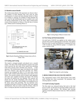
3.2 Load Deflection Characteristics
The corner beam-column joint specimen was subjected to
cyclic loading simulating earthquake loads. The load was
applied by using screw jack. Totally 6 cycles were imposed.
The beam-column joint was gradually loaded by the load level
during each cycle. As the load level was increased in each
cycle, the observed deflection was greater than it was in earlier
cycle.
Fig 5: Load Vs Displacement Curve Subjected to Cyclic
Loading
3.3 Mode of Failure
The corner beam-column joint test specimen was tested under
cyclic loading. During the forward loading cracks have been
developed at the top of the specimen As the loading was
progressed the width of crack has been widened. And the
reverse of the load specimen has to be in the reverse positions,
cracks have been formed at the bottom tension and the cracks
already formed in the tension face have to be closed. This
opening and closing of the cracks has been confirmed till the
final failure of the specimen takes place. The complete failure
pattern of the Beam-Column joint is shown in fig.6.
Fig 6: Failure at Ultimate Load
4. CONCLUSIONS
As the load level was increased in each cycle, the observed
deflection was greater than it was in earlier cycle.
During the forward loading cracks have been developed at the
top of the specimen As the loading was progressed the width
of crack has been widened. And the reversal of load specimen
has to be in the reversed positions, cracks have been formed at
the bottom tension and the cracks already formed in the
tension face have to be closed.
REFERENCES
[1]. Antonopoulos C.P. and Triantafillou T. C., (2002)
“Analysis of FRP-Strengthened RC Beam-Column Joints”,
Journal of Composites for Construction-Volume 6, Issue 1, pp.
41-51
[2]. Calvi, GM, Magenes, G, Pampanin, S, (2002),
Experimental Test on a Three Storey Reinforced Concrete
Frame Designed for Gravity Only, 12th European Conference
on Earthquake Engineering, paper n.727
[3]. G.A.Lakshmi, Anjan Dutta and S.K.Deb, (2008)
“Numerical studies of strengthening of beam column joint
under cyclic excitation using FRP composites” Journals of
structural Engineering, Vol 35,No 1, pp 59-65.
[4]. Gopal Rai, (2010) “Fiber Reinforced Polymer
Composites, A novel way for strengthening structures”, ICI-Asian
Conference on Ecstacy of Concrete
[5]. N.Vijayalakshmi, M.Kalaivani, A.Murugesan,
G.S.Thirugnanam, (2010)“ Experimental Investigation of RC
Beam Column Joint Strengthening by FRP Wrapping” civil
and structural engineering Volume 1, No 1,
[6]. Tsonos, A. G., (2001) “Seismic Retrofit of R/C Beam-to-
Column Joints using Local Three-Sided Jackets,” European
Earthquake Engineering, No. 1, pp. 48-64.
[7]. IS 13920-1993 Earthquake Engg. Code Clause no. 6, 7,
8.1 & 8.2](https://image.slidesharecdn.com/behaviourofbeam-columnjointundercyclicloading-140822045102-phpapp02/85/Behaviour-of-beam-column-joint-under-cyclic-loading-3-320.jpg)

This document discusses the behavior of beam-column joints in reinforced concrete structures under cyclic loading, emphasizing their vulnerability to seismic forces. It includes experimental procedures and results from tests on four joints, analyzing load-displacement relationships and cracking patterns. The findings highlight the importance of proper design and detailing to improve the seismic performance of these joints.