
Recommended
More Related Content
What's hot
What's hot (20)
Similar to Pre stressed concrete construction
Similar to Pre stressed concrete construction (20)
Recently uploaded
Recently uploaded (20)
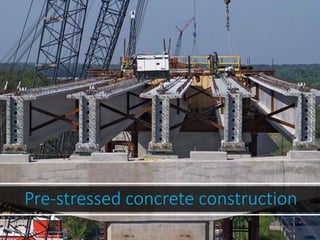
Pre stressed concrete construction
- 2. What is Pre-stressedConcrete? 2 – Internal stressesare induced to counteract external stresses. – In 1904, Freyssinet attempted to introduce permanent acting forcein conc. to resist elastic forces under loads and was named “Pre stressing”.
- 3. Introduction 3 • In prestressed concrete applications, most important variable is the prestress. • Prestress does not remain constant with time. • Even during prestressing of tendons, and transfer of prestress, there is a drop of prestress from the initially applied stress. • Reduction of prestress is nothing but the loss in prestress.
- 4. Reinforced concrete: • Concrete is strong in compression weak intension. • Steel in strong intension • Reinforced concrete usesconcrete to resist compression and to hold bars in position and uses steel to resist tension. • Tensile strength of concrete is neglected (i.e. zero) • R.Cbeams allows crack under serviceload.
- 7. Concept of pre-stressing: i . Theconcept of pre stressing was invented invented years ago when metal wound around wooden pieces to formbarrels. brands were ii . Themetal brands were tighten under tensile stresswhich creates compression between the staves allowing them to resist internal liquid pressure.
- 8. Principle of pre-stressing: • Pre-stressing is amethod in which compression forceis applied to the reinforcedconcrete section. • The effect of pre stressing is to reduce the tensile stress in the section to the point till the tensile stress is below the cracking stress. Thusthe concrete does not crack. • It is then possible to treatconcrete asaelastic material. • Theconcrete can be visualized to have two compressiveforce i .Internal pre-stressing force. ii . External forces (d.l , l.l etc ) • Thesetwo forces must counteract eachother.
- 9. Principle ofPre-stressing: • Stress in concrete when pre stressing is applied at thec.g of the section
- 10. Principle of Pre-stressing: • Stress in concrete when pre stressing is appliedeccentrically with respect to the c.g of the section.
- 11. Types of Prestressing Systems 11 I..Pre-tensioning: In Pre-tension, the tendons are tensioned before the concrete is place.After the concrete hardened, the tension force isreleased. II..Post tensioning: In Posttension, the tendons are tensioned afterthe concrete hashardened.
- 12. Types of pre-stressing: I .Pre-tensioning • InPre-tension, the tendonsaretensioned againstsome abutments before the concrete isplace.After the concrete hardened, the tension force isreleased. Thetendon tries to shrink backto the initial length but the concrete resistsit through thebond between them, thus,compressionforce is induced in concrete. Pretension isusuallydonewithprecast members
- 14. • Pre tensioned Concrete In which the tendons are tensioned before the concrete is placed, tendons are temporarily anchored and tensioned and the prestress is transferred to the concrete after it is hardened.
- 15. Pre-tensioning Method Stage 1 Stage 2 Stage 3 Stage 4 Tendons and reinforcement are positioned in the beam mould. Tendons are stressed to about 70% of their ultimate strength. Concrete iscast into the beam mould and allowed to cure to the required initial strength. When the concrete has cured the stressing force is released and the tendons anchor themselves in the concrete.
- 16. Exampleof Pre-tensioning 16 Fig: Pre-tensioned electricpole
- 17. II .Posttensioning • In Post tension, the tendons are tensioned after the concrete has hardened. Commonly, metal or plastic ducts are placed inside the concrete before casting. After the concrete hardened and had enough strength, the tendon was placed inside the duct, stressed, and anchored against concrete. Grout may be injected into the duct later. Thiscan be done either asprecast or cast-in-place.
- 18. Post tensioning
- 21. Post-tensioning Method Stage 1 Stage 2 Stage 3 Stage 4 Cable ducts and Concrete is cast Tendons are Wedges are inserted reinforcement are into the beam threaded through the into the end positioned in the beam mould and allowed cable ducts and anchorages and the mould. The ducts are to cure to the tensioned to about tensioning force on usually raised towards required initial 70% oftheir the tendons is the neutral axis at the strength. ultimate strength. released. Grout is ends to reduce the then pumped into eccentricity ofthe the ducts to protect stressing force. the tendons.
- 22. Forms • Wires • Strands • Tendons • Cables • Bars Source of Force • Mechanical • Hydraulic • Electrical Prestressing Steel (High Strength steel) tendons Mechanicaljacks tendons wires
- 24. Exampleof Post-tensioning 24 Fig: Post-tensioning of aboxgirder
- 25. Advantages: •Takefull advantages of high strengthconcrete and high strength steel •Need less materials •Smaller and lighter structure •No cracks •Usethe entire section toresist the load •Better corrosion resistance •Good for water tanks and nuclearplant •Very effective for deflectioncontrol •Better shearresistance
- 26. Disadvantagesof Pre-stressed concrete • Needhigherqualitymaterials • More complextechnically • Moreexpensive • Hardertore-cycle
- 27. Application: • Bridges • Slabsin buildings • WaterTank • ConcretePile • ThinShellStructures • OffshorePlatform • NuclearPowerPlant • RepairandRehabilitations
- 28. Losses in Various Prestressing Systems 28 Type of Loss Pre-tensioning Post-tensioning 1. Elastic Shortening Yes i. No, if all the cables are simultaneously tensioned. ii. If the wires are tensioned in stages loss will exist. 2. AnchorageSlip No Yes 3. Friction Loss No Yes 4. Creep and Shrinkage of Concrete Yes Yes 5. Relaxation of Steel Yes Yes
- 29. ElasticShortening 29 Length after elasticshortening • It is the shorten of concrete member, when the prestress is transferred to concrete, the member shortens and the prestressing steel also shortens in it. Hence there is a loss of prestress. Original length of member at transfer ofprestress Pi P0
- 30. Elastic Shortening at Pre-tensionedMembers 30 When the tendons are cut and the prestressing force is transferred to the member, concrete undergoes immediate shortening due toprestress. Tendon also shortens by same amount, which leads to the loss ofprestress.
- 31. Prestressing bed Pre-tensioning of amember Elastic Shortening at Pre-tensionedMembers 31
- 32. Elastic Shortening at Post-tensionedMembers If there is only one tendon, there is no loss because the applied prestressis recordedaftertheelastic shortening of themember. For more than one tendon, if the tendons are stretched sequentially, there is loss in a tendon during subsequent stretchingoftheothertendons. 32
- 33. Duct jackAnchorage Casting bed Post-tensioning of amember Elastic Shortening at Post-tensionedMembers 33
- 34. TERMINOLOGY 1.Tendon: A stretched element used in aconcrete member of structure to impart prestress to the concrete. 2.2.Anchorage: A device generally used to enable the tendon to • impart and maintain prestress in concrete.
- 35. Anchorage Slip 35 • In most Post-tensioning systems when the prestress force is transferred from the jack to the anchoring ends, the wedges slip over a smalldistance. • Loss of prestress is due to the consequent reduction in the length of thetendon. • Amount of slip depends on type of anchorage system.
- 36. Forcevariation diagramsforvarious stages 22 length lset. a)Theinitial tension at the right end is high to compensate forthe anchorage slip. It corresponds to about initial prestress. The force variation diagram (FVD)is linear. b)After the anchorage slip, the FVDdrops near the right endtill the lengthlset. Note : Effect of anchorage slip is present up to a certain length, called the setting
- 37. Forcevariation diagramsforvarious stages 37 c)Theinitial tension at the leftend also corresponds to about initial prestress. The FVD is linear up to the centre line of thebeam. d)After the anchorage slip, the FVDdrops near the left end till the length lset. It is observed that after two stages, the variation of the prestressing force over the length of the beam is less than after the first stage.
- 38. Typical values of anchorage slip 38 Anchorage System Anchorage Slip (Δs) Freyssinet system 12 - 5mm Φ strands 12 - 8mm Φ strands 4 mm 6 mm Magnel system 8 mm Dywidag system 1 mm
- 39. Frictional Loss 39 • Thefriction generated at the interfaceof concrete and steel during the stretching of acurved tendon in apost-tensioned member. • Thefriction in the jacking anchoring systemis generally small. • More serious frictional loss occurs betweenthe tendon and its surroundingmaterial.
- 40. Frictional loss occurs only inPost- tensioned Members 40 • Theloss due to friction does not occur in pre- tensioned members becausethere is noconcrete during the stretching of thetendons. • Friction is generated due to curvature of tendon, and vertical component of the prestressing force. A typical continuous post-tensioned member
- 41. FrictionalLoss •Frictional Lossis the summation of – Friction LossDueto lengthEffect. – Friction LossDueto CurvatureEffect. • LengthEffect:If theprofileofcableislinear,the loss 41 will be due to straightening or stretching of the cables. • Curvature Effect: If the profile is curved, there will be loss in stress due to friction between tendon and the duct or between the tendonsthemselves.
- 43. Methods availableto “Reduce”the frictional losses 43 1. Cablesshould passthrough metal tubes. 2. Thebends should be through assmall an angle aspossible. 3. Radiusof curvature for bends shouldbe large. 4. Prestressing the wire from bothends. 5. Over-tensioning the wires.
- 44. Creep of Concrete • TheContinuousdeformationofconcretewithtimeunder sustainedload. Factorsaffectingcreepofconcrete • Age • Applied Stresslevel • Density ofconcrete • CementContent inconcrete • Water-CementRatio • Relative Humidityand • Temperature 44
- 45. Condition for calculating the loss of prestress due to creep. 45 • Creep is due to sustained (permanent) loads only.Temporary loads are not considered in calculationof creep. • Since the prestress may vary along the length of the member, an average value of the prestress isconsidered.
- 46. Shrinkage of Concrete 46 • Shrinkage defined of concrete is as the contraction due to loss of moisture. • Due to the shrinkage of concrete,the prestress in the tendon is reduced withtime.
- 47. Shrinkageof Concrete 47 • For pre-tensioned members, transfer commonly takes place after 24 hours after casting and nearly all shrinkage takesplace after that. • For post-tensioned members, stressing may takes place after one day or much later, thusa large percentage of shrinkage may already taken place by them.
- 48. Relaxation 48 Relaxation is the reduction in stress with time at constant strain. – decrease in the stress is due to the fact that some of the initial elastic strain is transformed in to inelastic strain under constantstrain. – Percentage of relaxation varies from 1 to5%.
- 49. Factors effecting Relaxation : 49 • Time • Initial stress • Temperatureand • Typeof steel.
- 50. Method Availableto ReduceTheLossdueto Relaxation 50 • Choiceof proper steel helps to reducethis loss. • Prestressed wires havelessercreep. • Galvanised wires also have no creep. • overstressing steel about 10%above its initial stressand then releasing it to the initial stress
- 51. Initial Prestress 51 • Deducting the loss due toanchorage take-up and friction, initial prestress isobtained. • If prestress is measured at the time of pulling the wire, the stress is termed asthe jackingstress. • if jacketing stress is treated astheinitial stress, effective stress is jacketing stress minusall losses.
- 52. EffectivePrestress 52 • Initial Prestressin steel minus the lossesis known asthe effective or designprestress. Effective prestress=Initial prestress-Losses Note: For Pre-Tension system , Pretension Lossesare used instead of losses. For Post-Tension system , Post-Tension Lossesare used instead of losses.
- 53. TotalAmount OfLossesAccordingToTensioningSystem 53 • Total pretension losses=Lossdue to creep+ Elastic shortening +Shrinkage+ Steel Relaxation. • Total post-Tension Loss=Lossdue to creep+ Elastic shortening +Shrinkage+ Steel Relaxation +Anchorageslip + Friction.
- 54. Prestress Loss 54 • loss in prestress is the difference between initial prestress and the effectiveprestress. • Loss of prestressaffects – the strength of memberand – member’sserviceability [Stresses in Concrete, Cracking,Camber and Deflection]
- 55. Types 55 Loss of prestress is classified into two types: 1. Immediate Losses immediate losses occur during prestressing of tendons, and transfer of prestress to concrete member. 2. Time Dependent Losses Time dependent losses occur during service life of structure.
- 58. TotalLosses 58 • It is difficult to generalize the amount of loss of prestress, becauseit is dependent on so many Factors : Theproperties of concrete & steel. Curing & moisture condition. Magnitude & time of application of prestress. Processof prestress.
- 59. Method of LossEstimation 59 • There are two methods that canbe usedto estimate lossesin prestressedconcrete: (a)lump sum approximations; (b)refined estimations. Oneshould keep in mind that allestimates for prestress loss are just that – ESTIMATIONS.
- 60. LumpSumEstimationForPrestress Loss 60 • First introduce by the ACI-ASCECommittee 423in 1958. Table:AASHTO Lump SumLosses. TotalLoss Typesof prestressingsteel f’c=28 MPa f’c=35 MPa Pretensioning strand 310MPa Posttensioningwire or strand 220MPa 230Mpa Bars 150MPa 160Mpa
- 61. AASHTO-LRFDSpecifications 61 For Lump-Sum estimates following conditions should met: 1. Members that are post-tensioned must benon-segmental members with spansless than 160 feet and concrete stressed an ageof 10-30days. 2. Members that are pretensioned must be stressed at an age where the concrete strength is notless than 3,500-psi. 3. Members must be made from normalweight concrete. 4. Members cannot be steam-cured, normoist-cured. 5. Theprestressing steel must be normal orlow-relaxation. 6. There must beAverage exposure conditions at thesite.
- 62. Thumbrule ofLosses 62 • For average steel and concrete properties ,the tabulated percentages may be taken asrepresentative of theaverage losses. Pretensioning,% Posttensioning.% Elasticshortening & bendingof concrete 4 1 Creepof concrete 6 5 Shrinkageof concrete 7 6 Steel relaxation 8 8 TotalLoss 25 20
- 63. Methods of Corrosion Protection Epoxy Coating Fusion bonded epoxy coating of steel bars to help prevent corrosion has been successfully employed in many applications because of the chemical stability of epoxy resins. Epoxy coated bars and fasteners should be done in accordance with ASTM A- 775 or ASTM 934. Coating thickness is generally specified between 7 to 12 mils. Epoxy coated bars and components are subject to damage if dragged on the ground or mishandled. Heavy plates and nuts are often galvanized even though the bar may be epoxy coated since they are difficult to protect against abrasion in the field. Epoxy coating patch kits are often used in the field for repairing nicked or scratched epoxy surfaces. Cement Grout filled corrugated polyethylene tubing is often used to provide an additional barrier against corrosion attack in highly aggressive soils. These anchors are often referred to as MCP or Multiple Corrosion Protection anchors. The steel bars are wrapped with an internal centralizer then placed inside of the polyethylene tube where they are then factory pre-grouted. When specifying couplings with MCP ground anchors, verify coupling locations with a Williams representative. Pre-Grouted Bars
- 64. Williams strand tendons contain an extruded high density polyethylene sheathing around each individual strand in the free-stressing portion of the anchorage. The sheathing is minimum 60 mils thick and applied once the 7-wire strand has been coated with a corrosion inhibiting compound. Extruded polyethylene sheathing provides a moisture tight barrier for corrosion protection and allows the strand to elongate freely throughout the free-stressing length during the prestressing operation Hot Dip Galvanizing Zinc serves as a sacrificial metal corroding preferentially to the steel. Galvanized bars have excellent bond characteristics to grout or concrete and do not require as much care in handling as epoxy coated bars. However, galvanization of anchor rods is more expensive than epoxy coating and often has greater lead time. Hot dip galvanizing bars and fasteners should be done in accordance with ASTM A-153. Typical galvanized coating thickness for steel bars and components is between 3 and 4 mils. 150 KSI high strength steel bars should always be mechanically cleaned (never acid washed) to avoid problems associated with hydrogen embrittlement. Extruded Polyethylene
- 65. Corrosion Inhibiting Wax or Grease with Sheath Williams corrosion inhibiting compounds can be placed in the free stressing sleeves, in the end caps, or in the trumpet areas. Often bars are greased/waxed and PVC is slipped over the greased/waxed bar prior to shipping. Each are of an organic compound with either a grease or wax base. They provide the appropriate polar moisture displacement and have corrosion inhibiting additives with self-healing properties. They can be pumped or applied manually. Corrosion inhibiting compounds stay permanently viscous, chemically stable and non-reactive with the prestressing steel, duct materials or grout. Both compounds meet PTI standards for Corrosion Inhibiting Coating. Coal Tar Epoxy Coal tar epoxy has shown to be abrasion resistant, economical and durable. This product when specified should meet or exceed the requirements of (a) Corp of Engineers C-200, C200a and (b) AWWA C-210-92 for exterior. Typically the thickness is between 8 and 24 mils. Make sure that the surfaces of the bar are clean and dry before coating.
- 66. Heat Shrink Tubing Heat Shrink Tubing provides a corrosion protected seal when connecting smooth or corrugated segments. Epoxy Coating PatchKits EpoxyCoatingPatchKitsare availableupon request. Anchor Head Protection The most important section of a ground anchor that needs adequate corrosion protection is the portion of the anchor exposed to air/oxygen. This is typically defined as the "anchor head", which generally consists of a steel bearing plate, a hex nut and washer for a bar system, or a wedge plate and wedges for a strand system. For permanent ground anchors it is best to galvanize the hex nut and plates even if the bar is epoxy coated. Galvanized components, if scratched during shipping, are less likely to provide corrosion protection at otherwise exposed anchor ends. FiberReinforced cause corrosion concerns than scratched epoxy coated components. TheNylon Cap end of the steel bar protruding out from the hex nut is often protected by the use of a plastic or steel end cap packed with grease or cement grout. Williams offers several different types of PVC and metal end caps to Strand EndCap Screw-On PVCCap Steel Tube Welded on Flangewith Threaded Screw Connections
- 67. Field Splice for Bars Continuous corrosion protection can even be accomplished for the MCP Pregrouted anchors manufactured from Williams Form Engineering. To achieve the equivalent levels of corrosion protection the coupled sections of bar anchors can be wrapped in a grease impregnated tape that is further protected with heat shrink sleeving. This scheme is acceptable by most governing agencies and is specified in the PTI Recommendations for Prestresed Rock and Soil Anchors.
- 68. 1) Jenil 2) Nalin 3) Sid 4) Riyan 5) Panjala