The document provides an overview of prestressed concrete structures including:
- Definitions of prestressing where internal stresses counteract external loads.
- The key terminology used including tendons, anchorage, pretensioning vs post-tensioning.
- The materials used including cement, concrete, and steel types.
- The stages of loading and advantages of prestressing over reinforced concrete.
- Details of pretensioning and post-tensioning systems including equipment, processes, and differences between the two methods.
Prestressed concrete structures and its applications By Mukesh Singh GhuraiyaMukesh Singh Ghuraiya
1. What is Prestressed??
2. Principle of Prestressed
3. Method of prestressing
4. Prestressed concrete structures
5. Advantages/application of Prestressed concrete
6. Disadvantages of Prestressed concrete
7. Comparison of RCC and Prestressed Concrete Flat Slabs
Prestressed concrete ,post tensioning ,pre tensioning, where normal concrete can not be used and need of more strength is required this type of concrete are used. Metal bars are replaced by the tendoms which are generally used to create tension in concrete. So because of that beam bends in upward direction and when load is applied it come in normal conditon.
this presentation has animations, play it in ms powerpoint as slideshow for better understanding.
this module includes
a) Introduction
b) Advantages and types of
pre-stressing
c) Pre-stressing systems
d) Materials for pre-stressing
E) PREREQUISITE OF SOM
Basic concepts – Advantages – Materials required – Systems and methods of prestressing –
Analysis of sections – Stress concept – Strength concept – Load balancing concept – Effect of
loading on the tensile stresses in tendons
Prestressed concrete is a structural material that allows for predetermined, engineering stresses to be placed in members to counteract the stresses that occur when they are subject to loading.
It is the presentation based on pre- stressed concrete construction which includes each and every point and scope which may be useful to civil engineering students
Vaccine management system project report documentation..pdfKamal Acharya
The Division of Vaccine and Immunization is facing increasing difficulty monitoring vaccines and other commodities distribution once they have been distributed from the national stores. With the introduction of new vaccines, more challenges have been anticipated with this additions posing serious threat to the already over strained vaccine supply chain system in Kenya.
Overview of the fundamental roles in Hydropower generation and the components involved in wider Electrical Engineering.
This paper presents the design and construction of hydroelectric dams from the hydrologist’s survey of the valley before construction, all aspects and involved disciplines, fluid dynamics, structural engineering, generation and mains frequency regulation to the very transmission of power through the network in the United Kingdom.
Author: Robbie Edward Sayers
Collaborators and co editors: Charlie Sims and Connor Healey.
(C) 2024 Robbie E. Sayers
Democratizing Fuzzing at Scale by Abhishek Aryaabh.arya
Presented at NUS: Fuzzing and Software Security Summer School 2024
This keynote talks about the democratization of fuzzing at scale, highlighting the collaboration between open source communities, academia, and industry to advance the field of fuzzing. It delves into the history of fuzzing, the development of scalable fuzzing platforms, and the empowerment of community-driven research. The talk will further discuss recent advancements leveraging AI/ML and offer insights into the future evolution of the fuzzing landscape.
About
Indigenized remote control interface card suitable for MAFI system CCR equipment. Compatible for IDM8000 CCR. Backplane mounted serial and TCP/Ethernet communication module for CCR remote access. IDM 8000 CCR remote control on serial and TCP protocol.
• Remote control: Parallel or serial interface.
• Compatible with MAFI CCR system.
• Compatible with IDM8000 CCR.
• Compatible with Backplane mount serial communication.
• Compatible with commercial and Defence aviation CCR system.
• Remote control system for accessing CCR and allied system over serial or TCP.
• Indigenized local Support/presence in India.
• Easy in configuration using DIP switches.
Technical Specifications
Indigenized remote control interface card suitable for MAFI system CCR equipment. Compatible for IDM8000 CCR. Backplane mounted serial and TCP/Ethernet communication module for CCR remote access. IDM 8000 CCR remote control on serial and TCP protocol.
Key Features
Indigenized remote control interface card suitable for MAFI system CCR equipment. Compatible for IDM8000 CCR. Backplane mounted serial and TCP/Ethernet communication module for CCR remote access. IDM 8000 CCR remote control on serial and TCP protocol.
• Remote control: Parallel or serial interface
• Compatible with MAFI CCR system
• Copatiable with IDM8000 CCR
• Compatible with Backplane mount serial communication.
• Compatible with commercial and Defence aviation CCR system.
• Remote control system for accessing CCR and allied system over serial or TCP.
• Indigenized local Support/presence in India.
Application
• Remote control: Parallel or serial interface.
• Compatible with MAFI CCR system.
• Compatible with IDM8000 CCR.
• Compatible with Backplane mount serial communication.
• Compatible with commercial and Defence aviation CCR system.
• Remote control system for accessing CCR and allied system over serial or TCP.
• Indigenized local Support/presence in India.
• Easy in configuration using DIP switches.
COLLEGE BUS MANAGEMENT SYSTEM PROJECT REPORT.pdfKamal Acharya
The College Bus Management system is completely developed by Visual Basic .NET Version. The application is connect with most secured database language MS SQL Server. The application is develop by using best combination of front-end and back-end languages. The application is totally design like flat user interface. This flat user interface is more attractive user interface in 2017. The application is gives more important to the system functionality. The application is to manage the student’s details, driver’s details, bus details, bus route details, bus fees details and more. The application has only one unit for admin. The admin can manage the entire application. The admin can login into the application by using username and password of the admin. The application is develop for big and small colleges. It is more user friendly for non-computer person. Even they can easily learn how to manage the application within hours. The application is more secure by the admin. The system will give an effective output for the VB.Net and SQL Server given as input to the system. The compiled java program given as input to the system, after scanning the program will generate different reports. The application generates the report for users. The admin can view and download the report of the data. The application deliver the excel format reports. Because, excel formatted reports is very easy to understand the income and expense of the college bus. This application is mainly develop for windows operating system users. In 2017, 73% of people enterprises are using windows operating system. So the application will easily install for all the windows operating system users. The application-developed size is very low. The application consumes very low space in disk. Therefore, the user can allocate very minimum local disk space for this application.
Industrial Training at Shahjalal Fertilizer Company Limited (SFCL)MdTanvirMahtab2
This presentation is about the working procedure of Shahjalal Fertilizer Company Limited (SFCL). A Govt. owned Company of Bangladesh Chemical Industries Corporation under Ministry of Industries.
Automobile Management System Project Report.pdfKamal Acharya
The proposed project is developed to manage the automobile in the automobile dealer company. The main module in this project is login, automobile management, customer management, sales, complaints and reports. The first module is the login. The automobile showroom owner should login to the project for usage. The username and password are verified and if it is correct, next form opens. If the username and password are not correct, it shows the error message.
When a customer search for a automobile, if the automobile is available, they will be taken to a page that shows the details of the automobile including automobile name, automobile ID, quantity, price etc. “Automobile Management System” is useful for maintaining automobiles, customers effectively and hence helps for establishing good relation between customer and automobile organization. It contains various customized modules for effectively maintaining automobiles and stock information accurately and safely.
When the automobile is sold to the customer, stock will be reduced automatically. When a new purchase is made, stock will be increased automatically. While selecting automobiles for sale, the proposed software will automatically check for total number of available stock of that particular item, if the total stock of that particular item is less than 5, software will notify the user to purchase the particular item.
Also when the user tries to sale items which are not in stock, the system will prompt the user that the stock is not enough. Customers of this system can search for a automobile; can purchase a automobile easily by selecting fast. On the other hand the stock of automobiles can be maintained perfectly by the automobile shop manager overcoming the drawbacks of existing system.
CFD Simulation of By-pass Flow in a HRSG module by R&R Consult.pptxR&R Consult
CFD analysis is incredibly effective at solving mysteries and improving the performance of complex systems!
Here's a great example: At a large natural gas-fired power plant, where they use waste heat to generate steam and energy, they were puzzled that their boiler wasn't producing as much steam as expected.
R&R and Tetra Engineering Group Inc. were asked to solve the issue with reduced steam production.
An inspection had shown that a significant amount of hot flue gas was bypassing the boiler tubes, where the heat was supposed to be transferred.
R&R Consult conducted a CFD analysis, which revealed that 6.3% of the flue gas was bypassing the boiler tubes without transferring heat. The analysis also showed that the flue gas was instead being directed along the sides of the boiler and between the modules that were supposed to capture the heat. This was the cause of the reduced performance.
Based on our results, Tetra Engineering installed covering plates to reduce the bypass flow. This improved the boiler's performance and increased electricity production.
It is always satisfying when we can help solve complex challenges like this. Do your systems also need a check-up or optimization? Give us a call!
Work done in cooperation with James Malloy and David Moelling from Tetra Engineering.
More examples of our work https://www.r-r-consult.dk/en/cases-en/
Welcome to WIPAC Monthly the magazine brought to you by the LinkedIn Group Water Industry Process Automation & Control.
In this month's edition, along with this month's industry news to celebrate the 13 years since the group was created we have articles including
A case study of the used of Advanced Process Control at the Wastewater Treatment works at Lleida in Spain
A look back on an article on smart wastewater networks in order to see how the industry has measured up in the interim around the adoption of Digital Transformation in the Water Industry.
Forklift Classes Overview by Intella PartsIntella Parts
Discover the different forklift classes and their specific applications. Learn how to choose the right forklift for your needs to ensure safety, efficiency, and compliance in your operations.
For more technical information, visit our website https://intellaparts.com
Sachpazis:Terzaghi Bearing Capacity Estimation in simple terms with Calculati...Dr.Costas Sachpazis
Terzaghi's soil bearing capacity theory, developed by Karl Terzaghi, is a fundamental principle in geotechnical engineering used to determine the bearing capacity of shallow foundations. This theory provides a method to calculate the ultimate bearing capacity of soil, which is the maximum load per unit area that the soil can support without undergoing shear failure. The Calculation HTML Code included.
Student information management system project report ii.pdfKamal Acharya
Our project explains about the student management. This project mainly explains the various actions related to student details. This project shows some ease in adding, editing and deleting the student details. It also provides a less time consuming process for viewing, adding, editing and deleting the marks of the students.
Student information management system project report ii.pdf
PSC Lecture PPT.pptx
1. PSC 01-INTRODUCTION
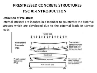
PRESTRESSED CONCRETE STRUCTURES
Definition of Pre-stress
Internal stresses are induced in a member to counteract the external
stresses which are developed due to the external loads or service
loads
2. Concept: Prestressed concrete is basically concrete in which internal
stresses of a suitable magnitude and distribution are introduced so
that the stresses resulting from the external loads are counteracted
to a desired degree.
Terminology
1. Tendon: A stretched element used in a concrete member of
structure to impart prestress to the concrete.
3. 2. Anchorage: A device generally used to enable the tendon to
impart and maintain prestress in concrete.
4.
5. 3. Pretensioning: A method of prestressingconcrete in which the
tendons are tensioned before the concrete is placed. In this
method, the concrete is introduced by bond between steel &
concrete.
4. Post-tensioning: A method of prestressingconcrete by tensioning
the tendons against hardened concrete. In this method, the
prestress is imparted to concrete by bearing.
Materials for prestress concrete members
Cement:
The cement used should be any of the following
•Ordinary Portland cement conforming to IS269
•Portland slag cement conforming to IS455. But the slag content should
not be more than 50%.
•Rapid hardening Portland cement conforming to IS8041.
•High strength ordinary Portland cement conforming to IS8112.
6. Concrete:
•Prestress concrete requires concrete, which has a high compressive
strength reasonably early age with comparatively higher tensile
strength than ordinary concrete.
•The concrete for the members shall be air-entrained concrete
composed of Portland cement, fine and coarse aggregates, admixtures
and water.
•The air-entraining feature may be obtained by the use of either air-
entraining Portland cement or an approved air-entraining admixture.
The entrained air content shall be not less than 4 percent or more than
6 percent.
•Minimum cement content of 300 to 360 kg/m3 is prescribed for the
durability requirement.
•The water content should be as low as possible
7. Steel
•High tensile steel , tendons , strands or cables
The steel used in prestress shall be any one of the following:-
•Plain hard-drawn steel wire conforming to IS1785 (Part-I & Part-III)
•Cold drawn indented wire conforming to IS6003
•High tensile steel wire bar conforming to IS2090
•Uncoated stress relived strand conforming to IS6006
Durability, Fire Resistance & Cover Requirements For
P.S.C Members:-
According to IS: 1343-1980
•20 mm cover for pretensioned members
•30 mm or size of the cable which ever is bigger for post tensioned
members.
•If the prestress members are exposed to an aggressive
environment, these covers are increased by another 10 mm.
8. Necessity of high grade of concrete & steel
•Higher the grade of concrete higher the bond strength which is vital
in pretensioned concrete, Also higher bearing strength which is vital
in post-tensioned concrete.
•Generally minimum M30 grade concrete is used for post-tensioned
& M40 grade concrete is used for pretensionedmembers
History and development of prestress
9. Forms of Prestressing Steel
•Wires: Prestressing wire is a single unit made of steel.
•Strands: Two, three or seven wires are wound to form a
prestressingstrand.
•Tendon: A group of strands or wires are wound to form a
prestressingtendon.
•Cable: A group of tendons form a prestressingcable.
•Bars: A tendon can be made up of a single steel bar. The diameter of a
bar is much larger than that of a wire.
Bonded tendon
When there is adequate bond between the prestressingtendon and
concrete, it is called a bonded tendon. Pre-tensioned and grouted post-
tensioned tendons are bonded tendons.
Unbondedtendon
When there is no bond between the prestressingtendon and concrete,
it is called unbondedtendon. When grout is not applied after post-
tensioning, the tendon is an unbondedtendon.
10. Stages of Loading
The analysis of prestressed members can be different for the
different stages of loading. The stages of loading are as follows.
1) Initial: It can be subdivided into two stages.
a) During tensioning of steel
b) At transfer of prestress to concrete.
2) Intermediate: This includes the loads during transportation of
the prestressed members.
3) Final: It can be subdivided into two stages.
a) At service, during operation.
b) At ultimate, during extreme events.
Advantages of Prestressing
•Section remains uncracked under service loads
•High span-to-depth ratios
•Suitable for precast construction
11. Limitations of Prestressing
•Prestressing needs skilled technology. Hence, it is not as common
as reinforced concrete.
• The use of high strength materials is costly.
• There is additional cost in auxiliary equipment.
• There is need for quality control and inspection.
Types of Prestressing
External or internal prestressing
Pre-tensioning or post-tensioning
Linear prestressing
Circular pre stressing
Full, limited or partial prestressing
Uniaxial, biaxial or multi-axial prestressing
12. Differences of Prestressed Concrete Over Reinforced Concrete
In prestress concrete member steel plays active role. The stress in steel
prevails whether external load is there or not. But in R.C.C., steel plays a
passive role. The stress in steel in R.C.C members depends upon the
external loads. i.e., no external load, no stress in steel.
In prestress concrete the stresses in steel is almost constant where as in
R.C.C the stress in steel is variable with the lever arm.
concrete has more shear resistance, where as shear resistance of R.C.C
is less.
In prestress concrete members, deflections are less
In prestress concrete fatigue resistance is more compare to R.C.C
In prestress concrete dimensions are less because external stresses are
counterbalance by the internal stress induced by prestress
Source of Prestressing Force
•Hydraulic Prestressing •Electrical Prestressing •Mechanical
Prestressing
13. Pre-tensioning Systems and Devices
Introduction
Stages of Pre-tensioning
Advantages of Pre-tensioning
Disadvantages of Pre-tensioning
Devices
Manufacturing of Pre-tensioned Railway Sleepers
Introduction
There are general guidelines of prestressing in Section 12 of
IS:1343 - 1980.
In pre-tensioning, the tension is applied to the tendons before
casting of the concrete.
The stages of pre-tensioning are described next.
14. Stages of Pre-tensioning
In pre-tensioning system, the high-strength steel tendons are pulled
between two end abutments (also called bulkheads) prior to the
casting of concrete
The abutments are fixed at the ends of a prestressing bed
Once the concrete attains the desired strength for prestressing, the
tendons are cut loose from the abutments.
The prestress is transferred to the concrete from the tendons, due to
the bond between them.
During the transfer of prestress, the member undergoes elastic
shortening. If the tendons are located eccentrically, the member is
likely to bend and deflect (camber).
15. The various stages of the pre-tensioning operation are summarized
as follows.
1) Anchoring of tendons against the end abutments
2) Placing of jacks
3) Applying tension to the tendons
4) Casting of concrete
5) Cutting of the tendons.
During the cutting of the tendons, the prestress is transferred to the
concrete with elastic shortening and camber of the member.
16.
17. Advantages of Pre-tensioning
The relative advantages of pre-tensioning as compared to post-
tensioning are as follows.
• Pre-tensioning is suitable for precast members produced in bulk.
• In pre-tensioning large anchorage device is not present.
Disadvantages of Pre-tensioning
The relative disadvantages are as follows.
• A prestressing bed is required for the pre-tensioning operation.
• There is a waiting period in the prestressing bed, before the
concrete attains sufficient strength.
• There should be good bond between concrete and steel over the
transmission length.
18. Devices
The essential devices for pre-tensioning are as follows.
• Prestressing bed
• End abutments
• Shuttering / mould
• Jack
• Anchoring device
• Harping device (optional)
19. Prestressing Bed, End Abutments and Mould
An extension of the previous system is the Hoyer system. This system is generally used
for mass production. The end abutments are kept sufficient distance apart, and several
members are cast in a single line. The shuttering is provided at the sides and
between the members. This system is also called the Long Line Method.
20. The end abutments have to be sufficiently stiff and have good
foundations
This is usually an expensive proposition, particularly when large
prestressing forces are required
The necessity of stiff and strong foundation can be bypassed by a
simpler solution which can also be a cheaper option. It is possible to
avoid transmitting the heavy loads to foundations, by adopting self-
equilibrating systems. This is a common solution in load-testing.
Typically, this is done by means of a ‘tension frame’.
21. The jack and the specimen tend to push the end members. But the
end members are kept in place by members under tension such as
high strength steel rods. The frame that is generally adopted in a pre-
tensioning system is called a stress bench. The concrete mould is
placed within the frame and the tendons are stretched and anchored
on the booms of the frame. The following figures show the
components of a stress bench.
Free body diagram by replacing
the jacks with the applied forces
22. Jacks The jacks are used to apply tension to the tendons. Hydraulic
jacks are commonly used. These jacks work on oil pressure generated
by a pump. The principle behind the design of jacks is Pascal’s law. The
load applied by a jack is measured by the pressure reading from a
gauge attached to the oil inflow or by a separate load cell. The
following figure shows a double acting hydraulic jack with a load cell.
23. Anchoring Devices
Anchoring devices are often made on the wedge and friction principle.
In pre-tensioned members, the tendons are to be held in tension during
the casting and hardening of concrete. Here simple and cheap quick-
release grips are generally adopted. The following figure provides some
examples of anchoring devices.
24. Harping Devices
The tendons are frequently bent, except in cases of slabs-on-grade,
poles, piles etc. The tendons are bent (harped) in between the
supports with a shallow sag as shown below.
25. Manufacturing of Pre-tensioned Railway Sleepers
The steel strands are stretched in a stress bench that can be
moved on rollers. The stress bench can hold four moulds in a
line. The anchoring device holds the strands at one end of the
stress bench. In the other end, two hydraulic jacks push a
plate where the strands are anchored. The movement of the
rams of the jacks and the oil pressure are monitored by a
scale and gauges, respectively. Note that after the extension
of the rams, the gap between the end plate and the adjacent
mould has increased. This shows the stretching of the strands.
The stress bench is moved beneath the concrete mixer. The
concrete is poured through a hopper and the moulds are
vibrated. After the finishing of the surface, the stress bench is
placed in a steam curing chamber for a few hours till the
concrete attains a minimum strength.
26.
27.
28.
29. Post-tensioning Systems and Devices
Introduction
There are general guidelines of prestressing in Section 12 of IS 1343:
1980. The information given in this section is introductory in nature,
with emphasis on the basic concepts of the systems.
In post-tensioning, the tension is applied to the tendons after
hardening of the concrete.
30. In post-tensioning systems, the ducts for the tendons (or strands) are
placed along with the reinforcement before the casting of concrete.
The tendons are placed in the ducts after the casting of concrete.
The duct prevents contact between concrete and the tendons during
the tensioning operation.
Unlike pre-tensioning, the tendons are pulled with the reaction
acting against the hardened concrete.
If the ducts are filled with grout, then it is known as bonded post-
tensioning.
The grout is a neat cement paste or a sand-cement mortar containing
suitable admixture.
Stages of Post-tensioning
31. In unbonded post-tensioning, as the name suggests, the ducts are
never grouted and the tendon is held in tension solely by the end
anchorages.
The profile of the duct depends on the support conditions. For a
simply supported member, the duct has a sagging profile between the
ends. For a continuous member, the duct sags in the span and hogs
over the support.
32.
33. The various stages of the post-tensioning operation are
summarised as follows
1) Casting of concrete.
2) Placement of the tendons.
3) Placement of the anchorage block and jack.
4) Applying tension to the tendons.
5) Seating of the wedges.
6) Cutting of the tendons
The stages are shown schematically in the following figures. After
anchoring a tendon at one end, the tension is applied at the other
end by a jack. The tensioning of tendons and pre-compression of
concrete occur simultaneously. A system of self-equilibrating forces
develops after the stretching of the tendons.
34.
35. Advantages of Post-tensioning
The relative advantages of post-tensioning as compared to pre-
tensioning are as follows.
• Post-tensioning is suitable for heavy cast-in-place members.
• The waiting period in the casting bed is less.
• The transfer of prestress is independent of transmission length.
Disadvantage of Post-tensioning
The relative disadvantage of post-tensioning as compared to pre-
tensioning is the requirement of anchorage device and grouting
equipment.
36. Devices
The essential devices for post-tensioning are as follows.
1) Casting bed
2) Mould/Shuttering
3) Ducts
4) Anchoring devices
5) Jacks
6) Couplers (optional)
7) Grouting equipment (optional).
38. Anchoring Devices
In post-tensioned members the anchoring devices transfer
the prestress to the concrete. The devices are based on the
following principles of anchoring the tendons.
1) Wedge action
2) Direct bearing
3) Looping the wires
39. Wedge action
The anchoring device based on wedge action consists of an anchorage
block and wedges. The strands are held by frictional grip of the
wedges in the anchorage block. Some examples of systems based on
the wedge-action are Freyssinet, Gifford-Udall, Anderson and Magnel-
Blaton anchorages. The following figures show some patented
anchoring devices.
40. Direct bearing
The rivet or bolt heads or button heads formed at the end of the wires
directly bear against a block. The B.B.R.V post-tensioning system and
the Prescon system are based on this principle. The following figure
shows the anchoring by direct bearing.
41. Looping the wires
The Baur-Leonhardt system, Leoba system and also the Dwidag single-
bar anchorage system, work on this principle where the wires are
looped around the concrete. The wires are looped to make a bulb. The
following photo shows the anchorage by looping of the wires in a
post-tensioned slab.
44. Couplers
The couplers are used to connect
strands or bars. They are located
at the junction of the members,
for example at or near columns in
post-tensioned slabs, on piers in
post-tensioned bridge decks.
The couplers are tested to
transmit the full capacity of the
strands or bars. A few types of
couplers are shown.
45. Grouting
Grouting can be defined as the filling of duct, with a material that
provides an anti-corrosive alkaline environment to the prestressing
steel and also a strong bond between the tendon and the surrounding
grout.
The major part of grout comprises of water and cement, with a water-
to-cement ratio of about 0.5, together with some water-reducing
admixtures, expansion agent and pozzolans. The properties of grout
are discussed in Section 1.6, “Concrete (Part-II)”. The following figure
shows a grouting equipment, where the ingredients are mixed and the
grout is pumped.