The document outlines the course content and structure for a Reinforced Concrete Design-II class taught by Prof. Dr. Qaisar Ali, including topics that will be covered in the midterm and final terms such as one-way slab design, two-way slab design, earthquake design, and retaining walls. The grading policy and availability of course materials online are also mentioned. The document serves as an introduction and overview for students taking the Reinforced Concrete Design-II course.
![Department of Civil Engineering, University of Engineering and Technology Peshawar
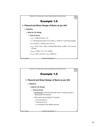
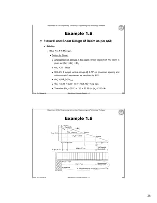
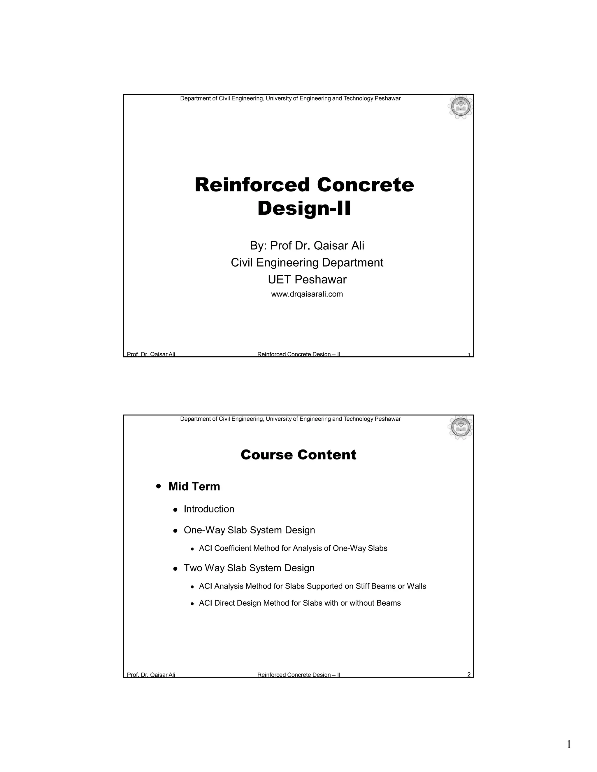
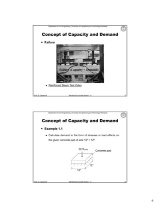
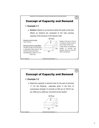
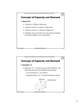
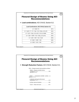
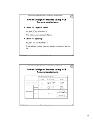
Example 1.6
Flexural and Shear Design of Beam as per ACI:
Solution:
Step No. 04: Design.
Design for flexure:
ΦMn ≥ Mu (ΦMn is Mdesign or Mcapacity)
For ΦMn = Mu
ΦAsfy(d – a/2) = Mu
As = Mu/ {Φfy (d – a/2)}
Calculate “As” by trial and success method.
Prof. Dr. Qaisar Ali
Reinforced Concrete Design – II
43
Department of Civil Engineering, University of Engineering and Technology Peshawar
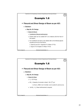
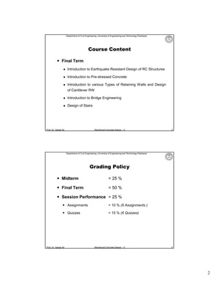
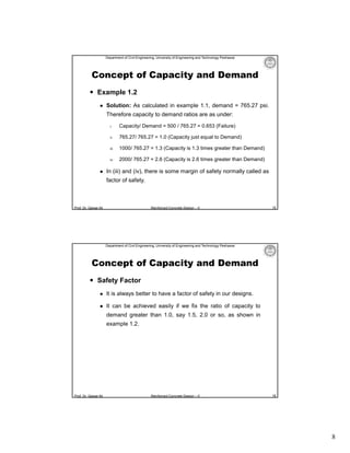
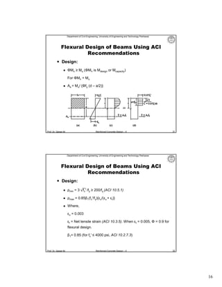
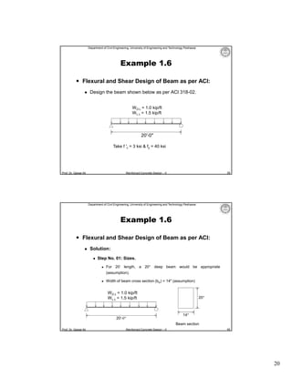
Example 1.6
Flexural and Shear Design of Beam as per ACI:
Solution:
Step No. 04: Design.
Design for flexure:
First Trial:
Assume a = 4″
As = 2370.24 / [0.9 × 40 × {17.5 – (4/2)}] = 4.25 in2
a = Asfy/ (0.85fc′bw)
Prof. Dr. Qaisar Ali
= 4.25 × 40/ (0.85 × 3 × 14) = 4.76 inches
Reinforced Concrete Design – II
44
22](https://image.slidesharecdn.com/l-01introduction-131121114659-phpapp02/85/Lecture-01-Introduction-to-Reinforced-Concrete-Design-22-320.jpg)
![Department of Civil Engineering, University of Engineering and Technology Peshawar
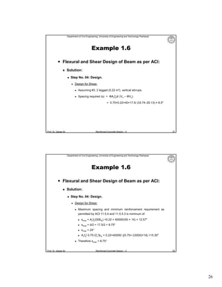
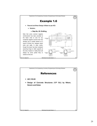
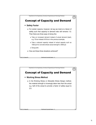
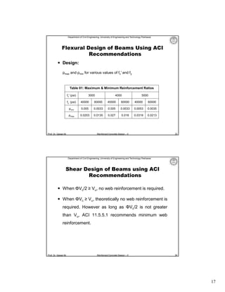
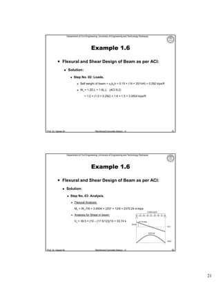
Example 1.6
Flexural and Shear Design of Beam as per ACI:
Solution:
Step No. 04: Design.
Design for flexure:
Second Trial:
• As = 2370.24 / [0.9 × 40 × {17.5 – (4.76/2)}] = 4.35 in2
• a = 4.35 × 40/ (0.85 × 3 × 14) = 4.88 inches
• As = 2370.24 / [0.9 × 40 × {17.5 – (4.88/2)}] = 4.37 in2
Third Trial:
• a = 4.37 × 40/ (0.85 × 3 × 14) = 4.90 inches
“Close enough to the previous value of “a” so that As = 4.37 in2 O.K
Prof. Dr. Qaisar Ali
Reinforced Concrete Design – II
45
Department of Civil Engineering, University of Engineering and Technology Peshawar
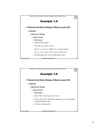
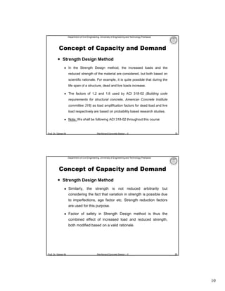
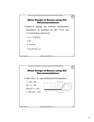
Example 1.6
Flexural and Shear Design of Beam as per ACI:
Solution:
Step No. 04: Design.
Design for flexure:
ρmin = 3
3 × 3000 /40000 = 0.004
200/40000 = 0.005
Therefore, ρmin = 0.005
Prof. Dr. Qaisar Ali
Check for maximum and minimum reinforcement allowed by ACI:
Asmin = ρminbwd = 0.005 × 14 × 17.5 = 1.225 in2
f′ /fy ≥ 200/fy (ACI 10.5.1)
Reinforced Concrete Design – II
46
23](https://image.slidesharecdn.com/l-01introduction-131121114659-phpapp02/85/Lecture-01-Introduction-to-Reinforced-Concrete-Design-23-320.jpg)