The document discusses the need for and components of a seal oil system for generators cooled with hydrogen. The key points are:
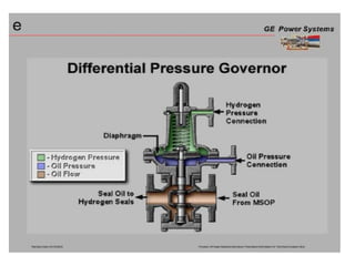
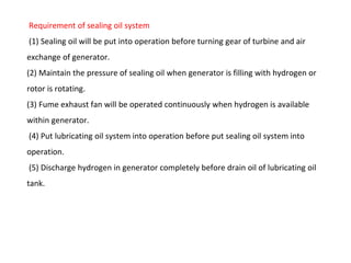
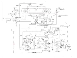
1) Seal oil systems use oil to maintain pressure higher than hydrogen pressure to prevent hydrogen leakage from generator shafts.
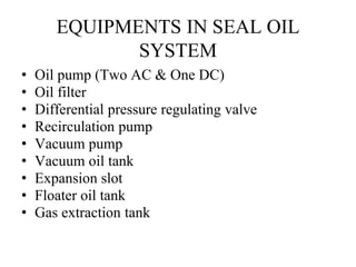
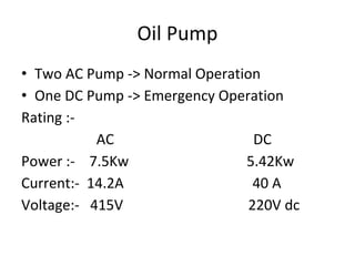
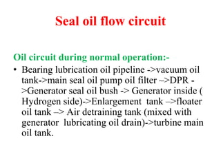
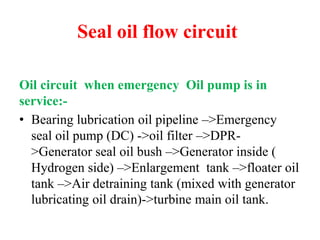
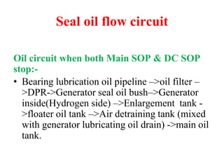
2) The system includes oil pumps, filters, regulating valves, tanks, and other equipment to circulate oil between the generator seals and vacuum/holding tanks where gas is extracted from the oil.
3) Proper operation and maintenance of the seal oil system is important to ensure differential pressure is maintained between the oil and hydrogen inside the generator.