Benjamin Johnson completed a conceptual design project for a two-seat, electrically powered training aircraft under the supervision of Liz Byrne at the University of Hertfordshire. The project report documents the research, design, and analysis conducted from the initial concept generation through the technical design of the aircraft's wing, fuselage, propulsion system, landing gear, structures, and stability and control surfaces. Appendices provide further details on specific areas like aerofoil selection, drag analysis, and 3D modelling. The designed aircraft is compared against the Cessna 152, an existing trainer aircraft, to evaluate the project outcomes.

![School of Engineering and Technology BEng Final Year Project Report
LIST OF FIGURES
Figure 1 - Jet Fuel and Crude Oil Price - [6] ................................................................................. 4
Figure 2 - Crude Oil Worldwide Distribution - [7] .......................................................................... 5
Figure 3 - E-FAN 2.0 - [15]............................................................................................................ 7
Figure 4 - E-FAN 4.0 - [15]............................................................................................................ 8
Figure 5 - Final Design Concept Sketch ....................................................................................... 9
Figure 6 - Design Development Process - [17] ........................................................................... 10
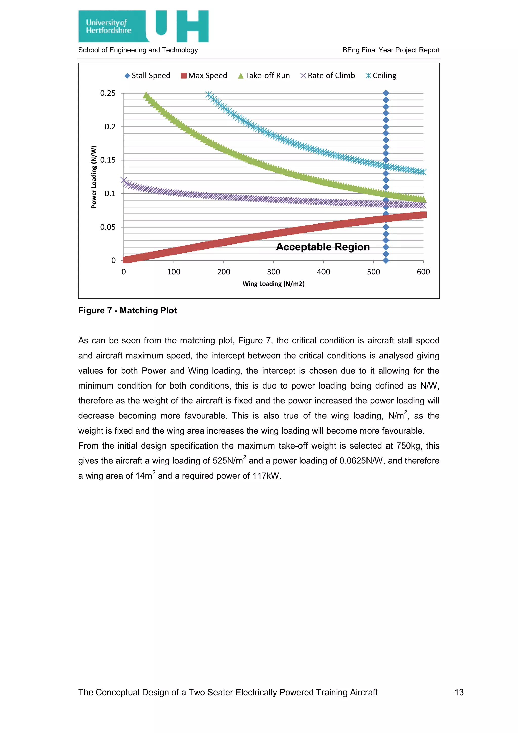
Figure 7 - Matching Plot .............................................................................................................. 13
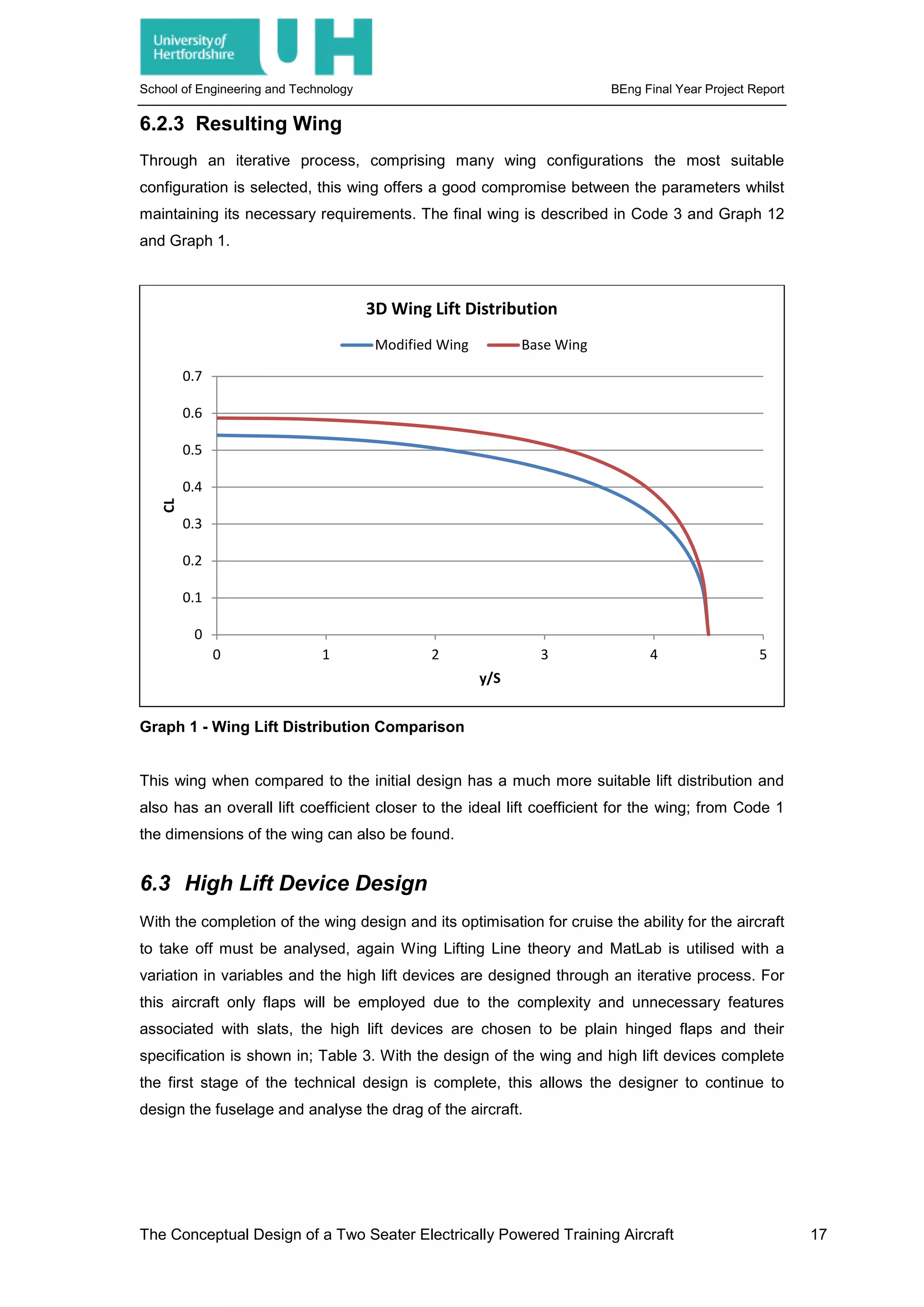
Figure 8 - Cockpit Elevation Sketches ........................................................................................ 18
Figure 9 - Induced Drag - [19] ..................................................................................................... 20
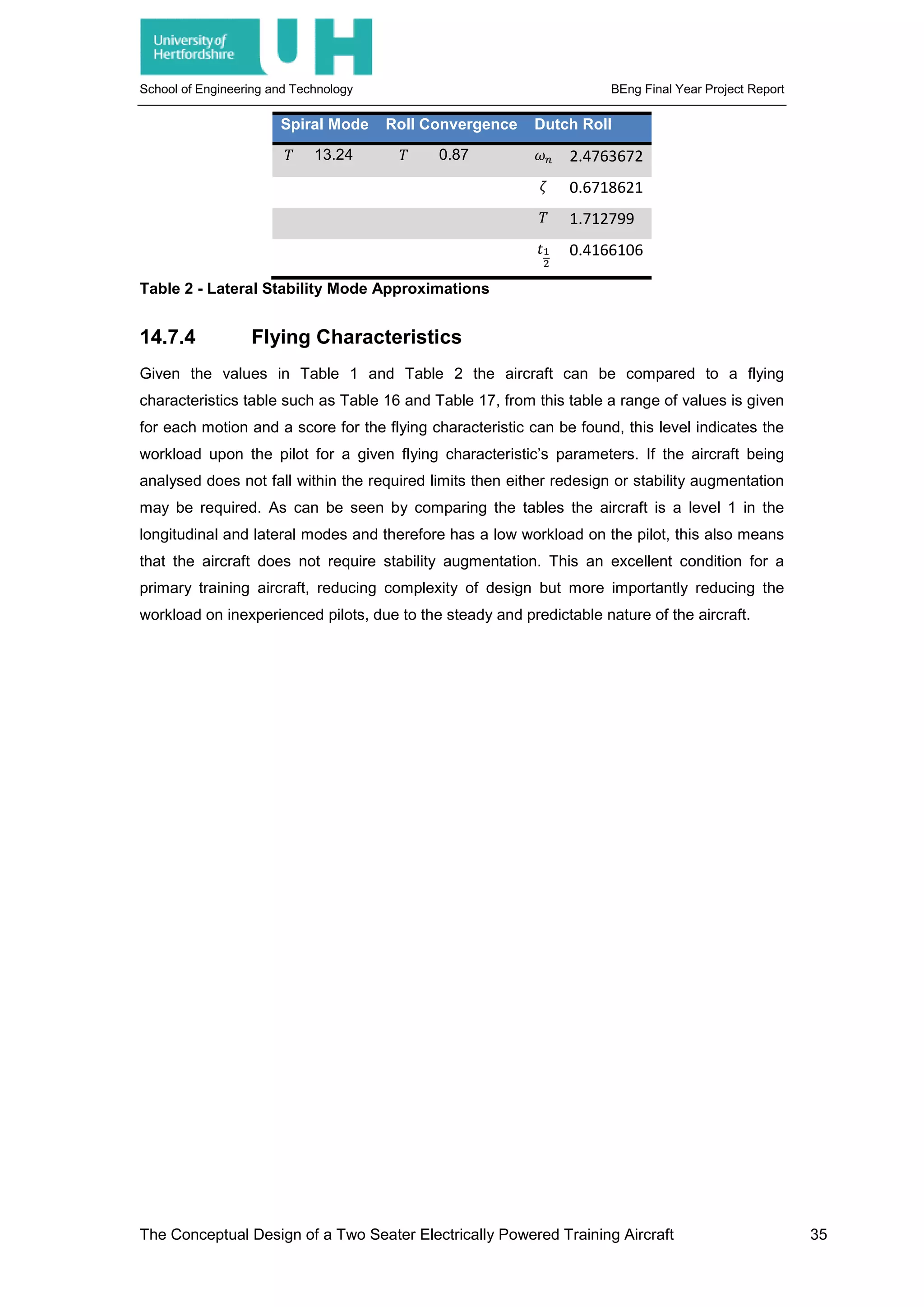
Figure 10 - Model Creation ......................................................................................................... 36
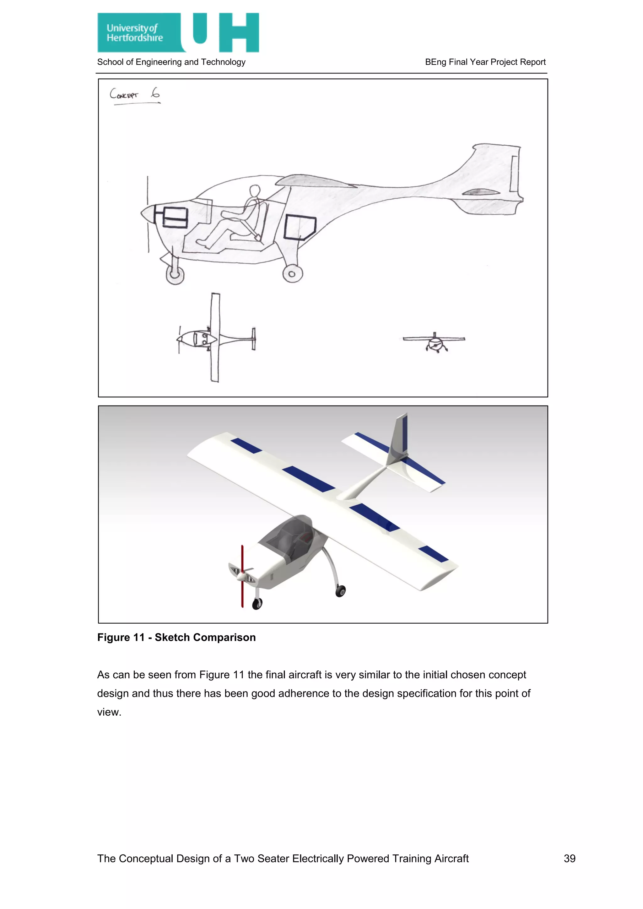
Figure 11 - Sketch Comparison .................................................................................................. 39
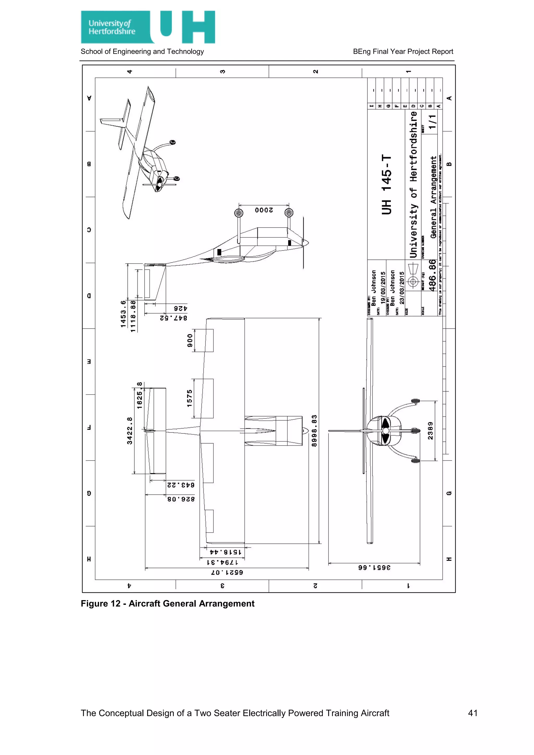
Figure 12 - Aircraft General Arrangement................................................................................... 41
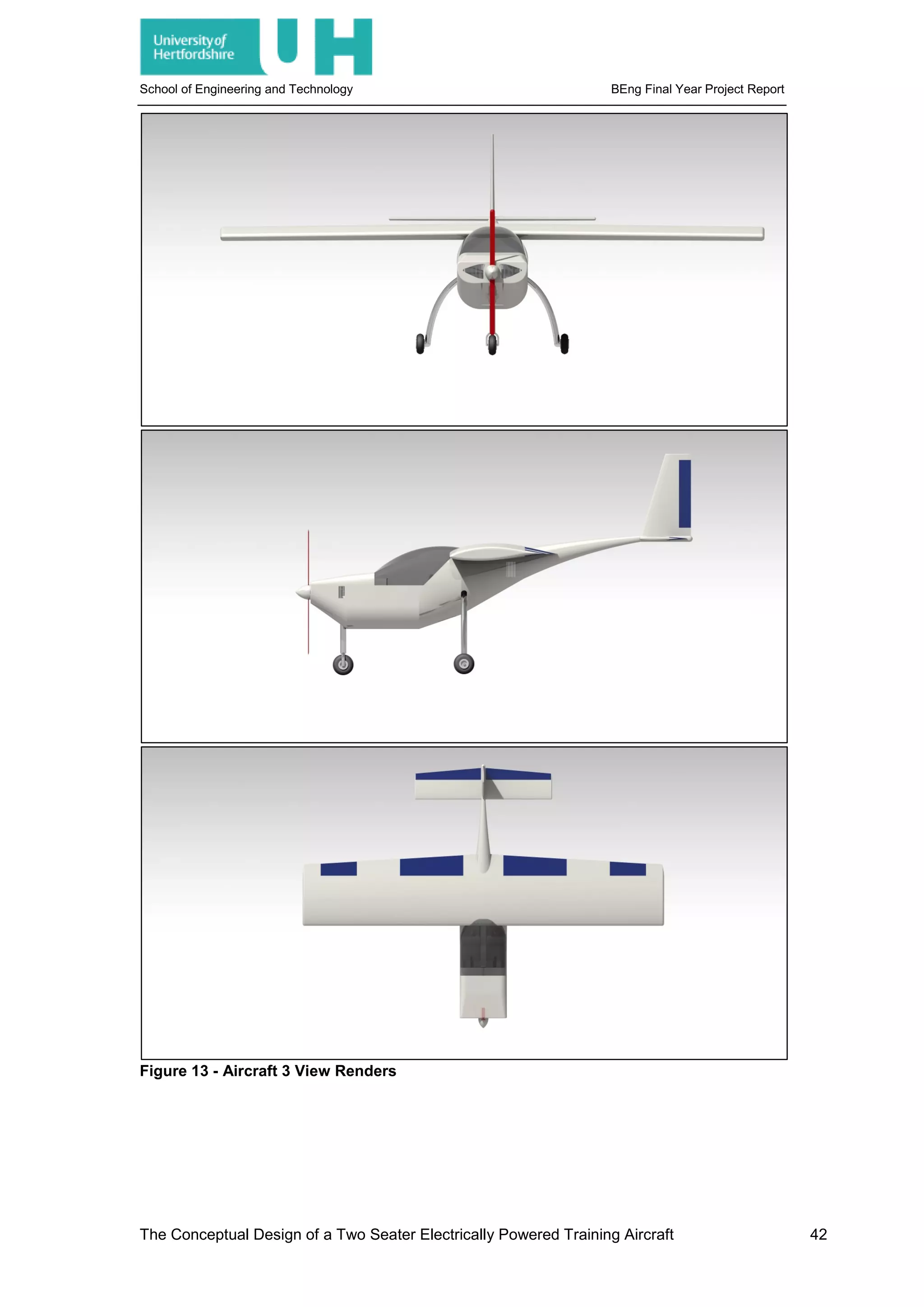
Figure 13 - Aircraft 3 View Renders............................................................................................ 42
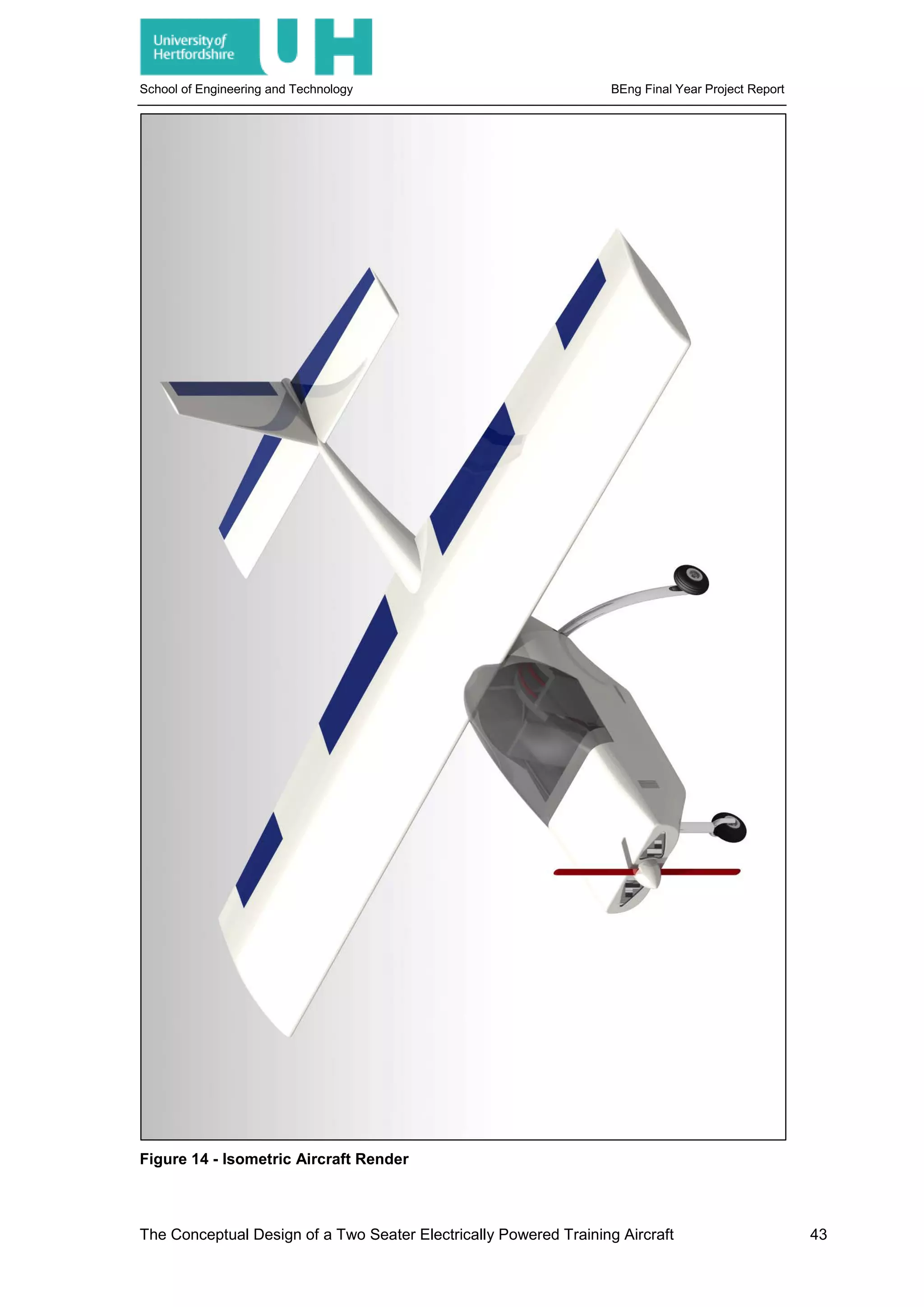
Figure 14 - Isometric Aircraft Render.......................................................................................... 43
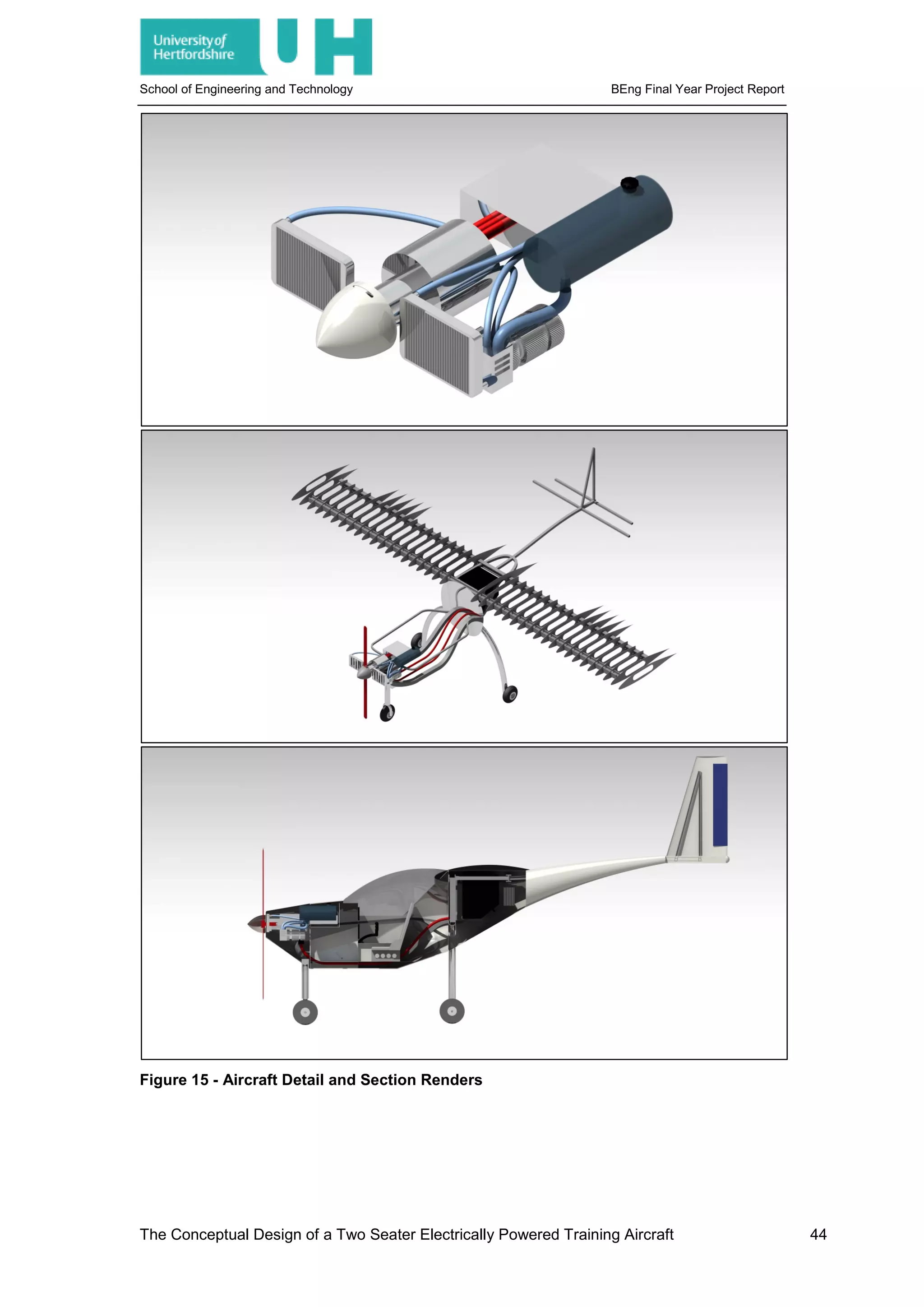
Figure 15 - Aircraft Detail and Section Renders ......................................................................... 44
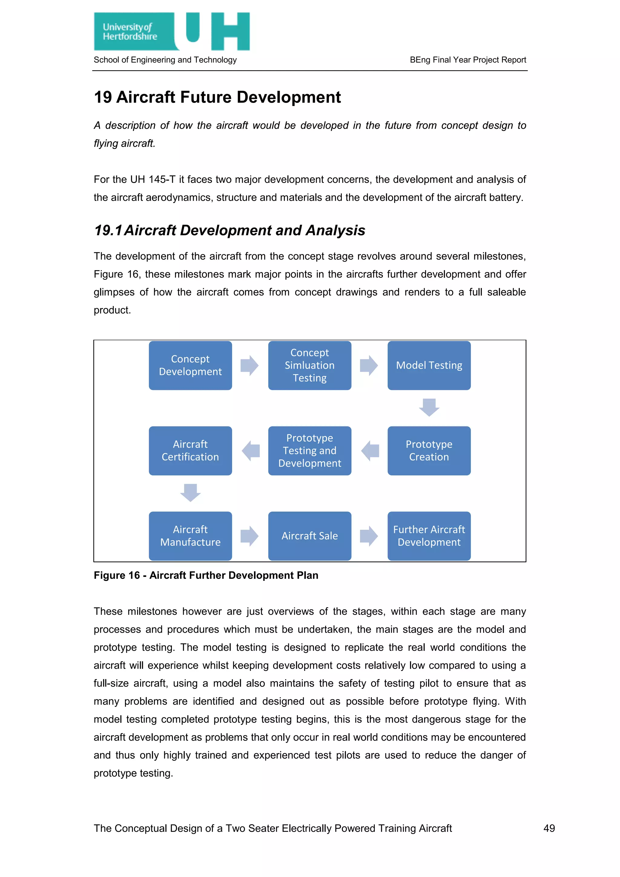
Figure 16 - Aircraft Further Development Plan ........................................................................... 49
Figure 17 - Energy Density Increases - [24], [25] ....................................................................... 50
Figure 18 - Cessna 152 3 View Sectional Drawing - [27] ........................................................... 62
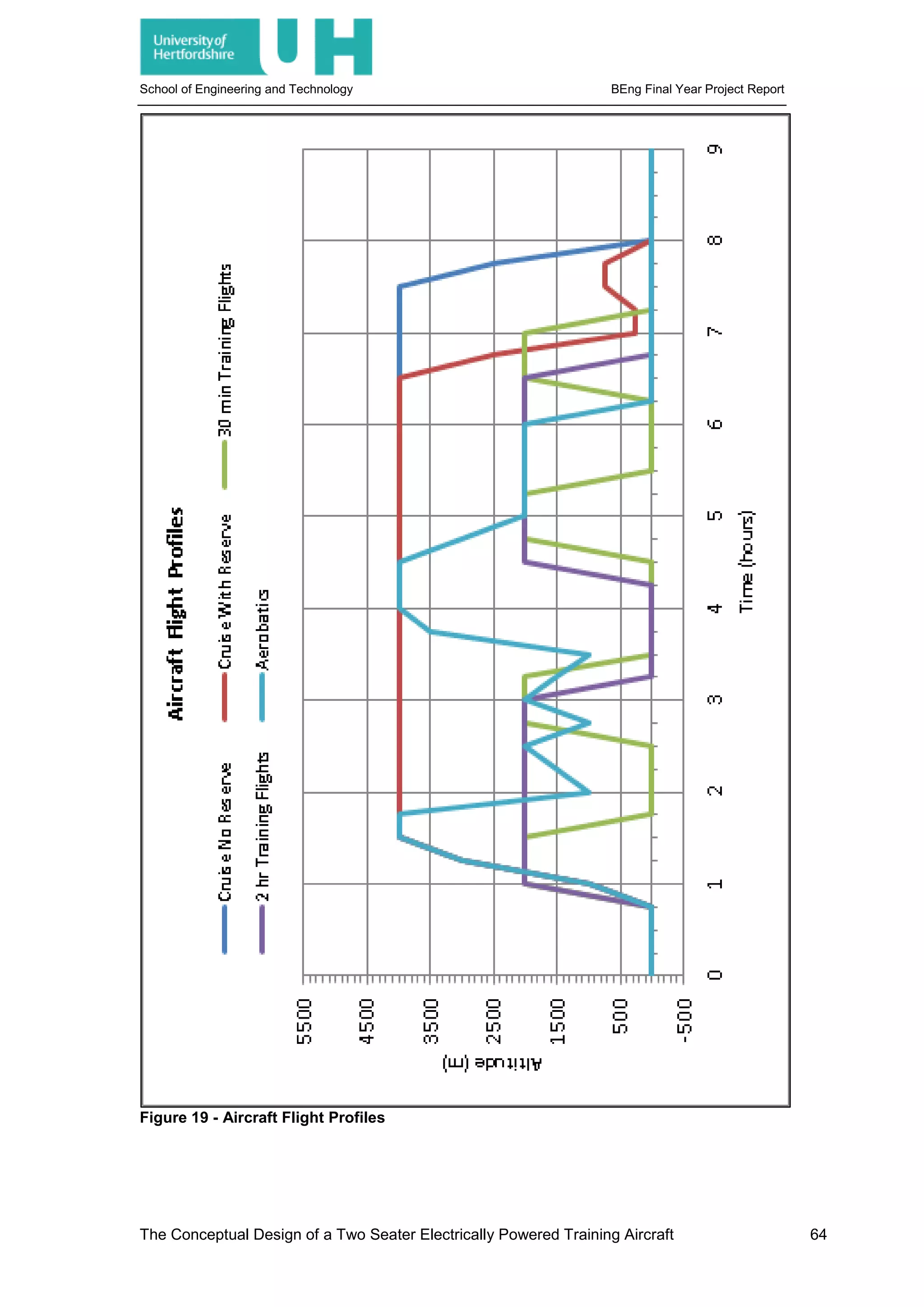
Figure 19 - Aircraft Flight Profiles................................................................................................ 64
Figure 20- Centre of Gravity Variation in Longitudinal Axis ........................................................ 72
Table 1 - Longitudinal Approximation Results ............................................................................ 31
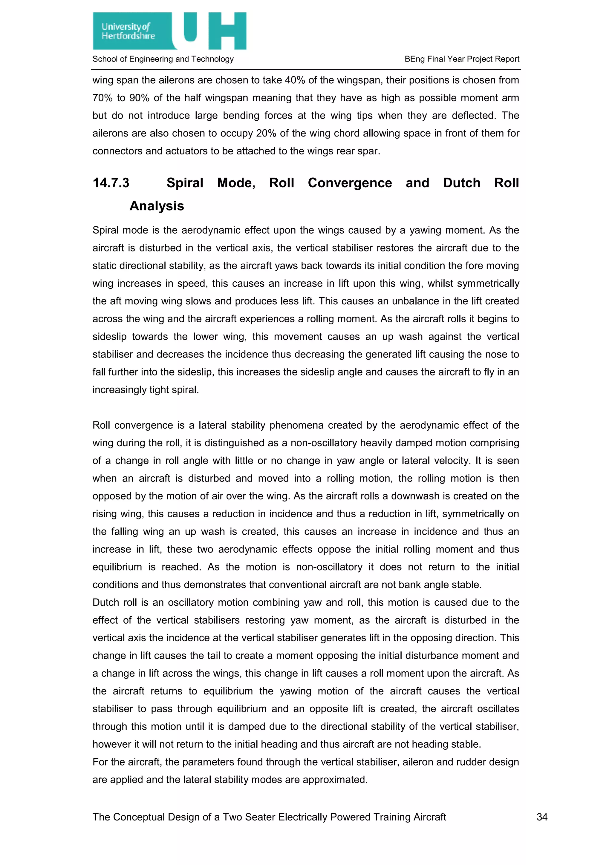
Table 2 - Lateral Stability Mode Approximations ........................................................................ 35
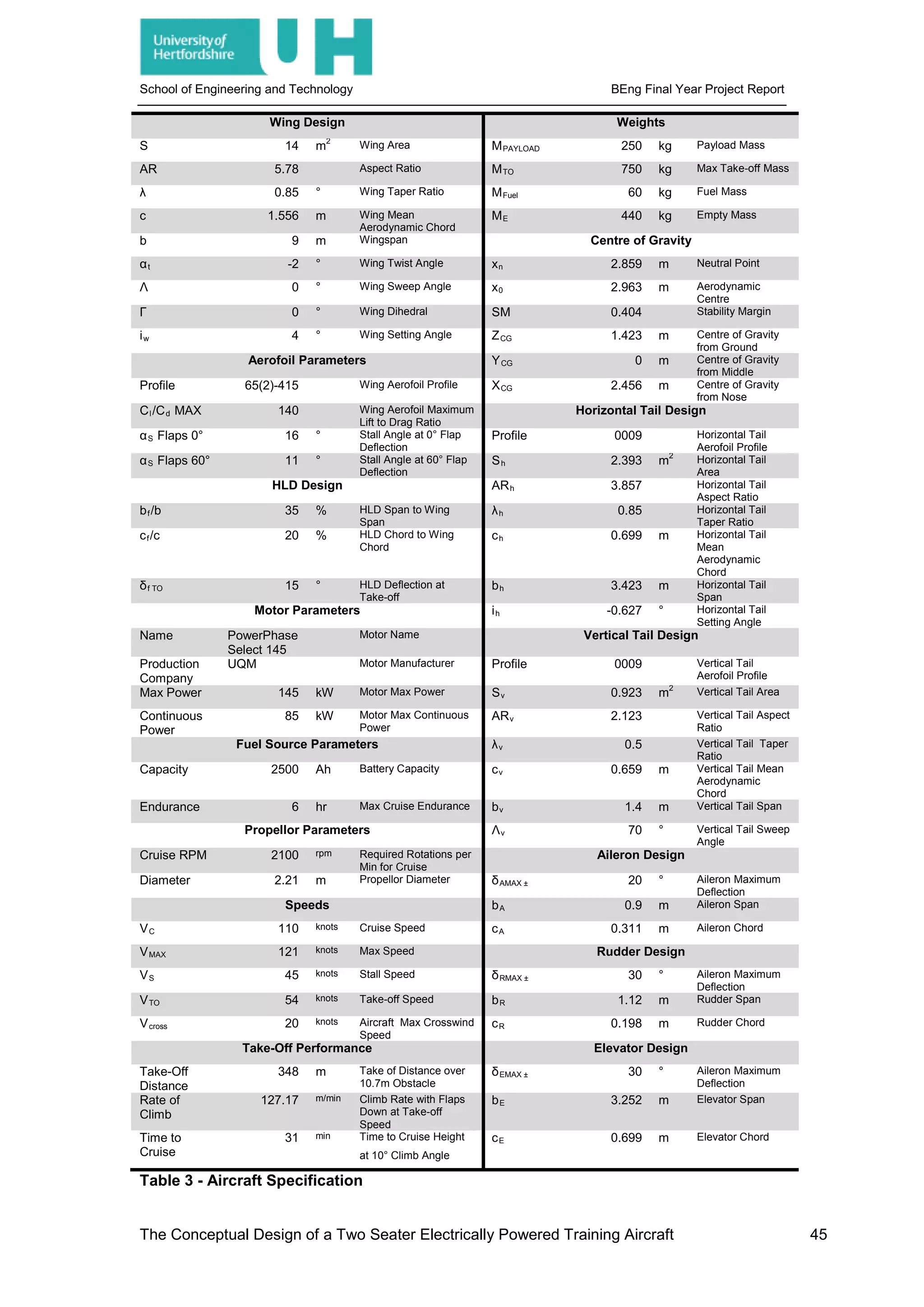
Table 3 - Aircraft Specification .................................................................................................... 45
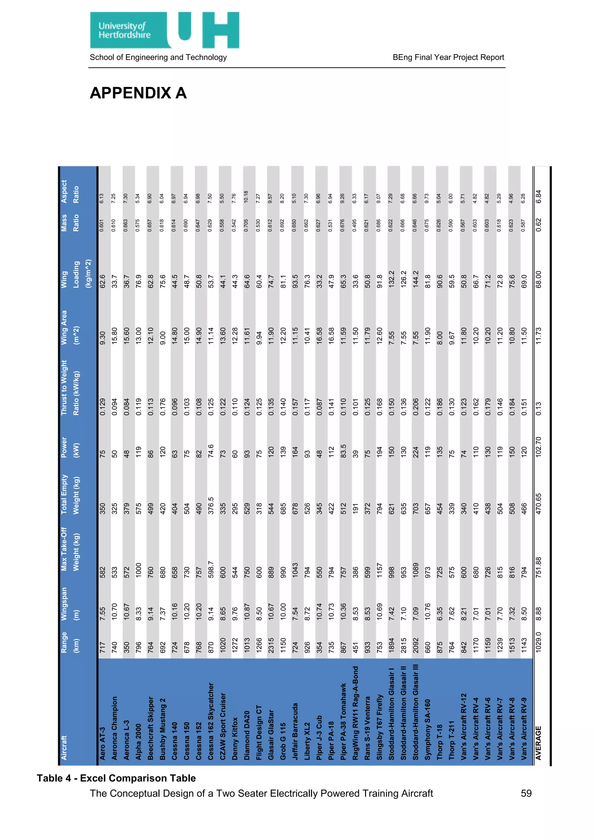
Table 4 - Excel Comparison Table.............................................................................................. 59
Table 5 – Cessna 152 Technical Specification - [26].................................................................. 61
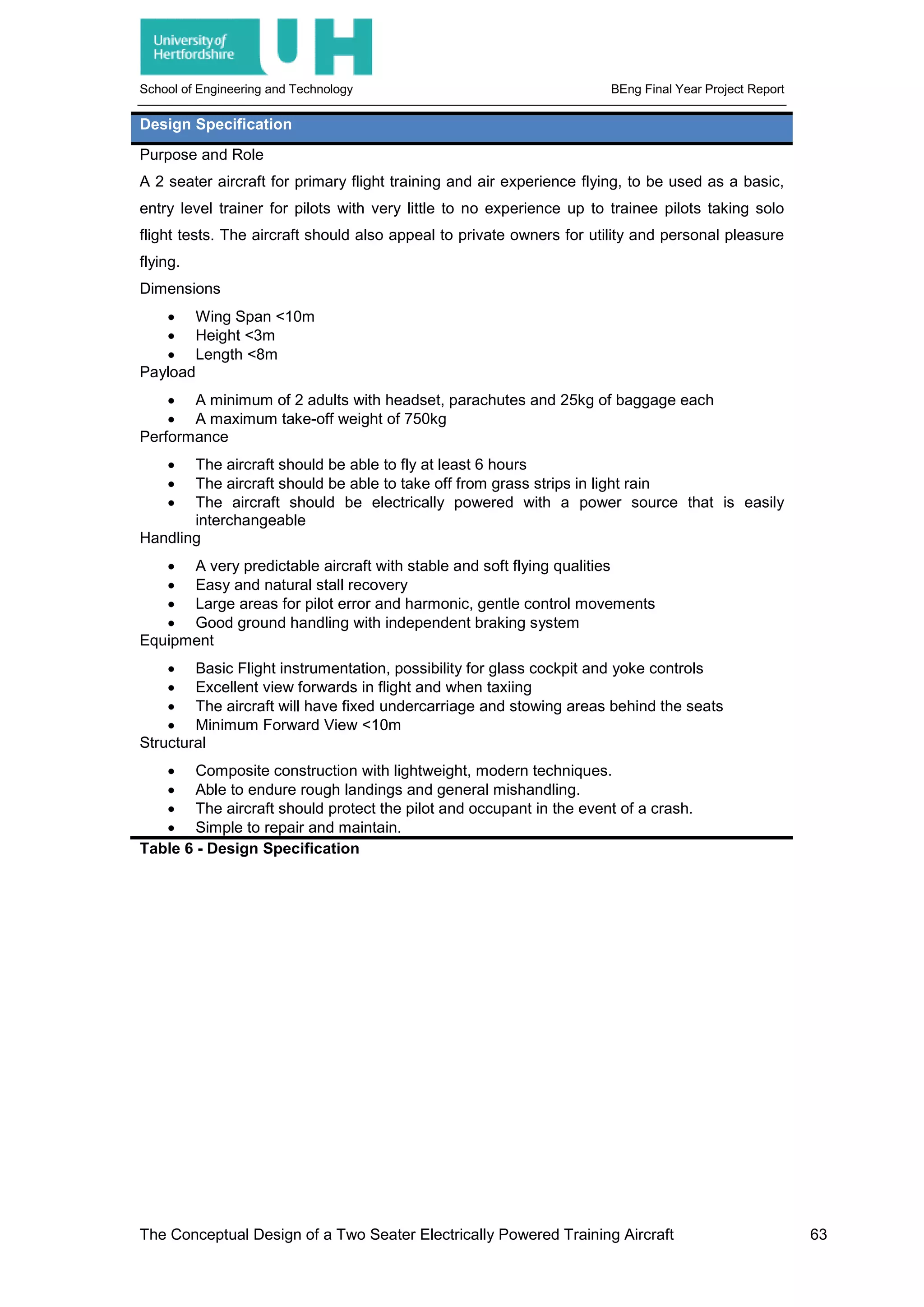
Table 6 - Design Specification .................................................................................................... 63
Table 7 - Undercarriage Loading ................................................................................................ 71
Table 8 - Component Moment Analysis...................................................................................... 71
Table 9 - Aircraft Centre of Gravity ............................................................................................. 72
Table 10 - Load Considerations .................................................................................................. 72
Table 11 – NACA 0009 Aerofoil Data ......................................................................................... 73
Table 12 - Wing Dimensions ....................................................................................................... 73
Table 13 - High Lift Device Dimensions...................................................................................... 73
Table 14 - Horizontal Stabiliser Parameters ............................................................................... 73
Table 15- Vertical Stabiliser Parameters..................................................................................... 74
Table 16 - Longitudinal Flying Characteristics - [28]................................................................... 74
The Conceptual Design of a Two Seater Electrically Powered Training Aircraft
ix](https://image.slidesharecdn.com/0442df0a-d8dc-4f9c-9b24-9e5eae2820ed-160330152913/75/JOHNSON_BENJAMIN_11379847_Report-10-2048.jpg)
![School of Engineering and Technology BEng Final Year Project Report
Table 17 - Lateral Flying Characteristics - [28] ........................................................................... 74
Code 1 - Wing Lift Distribution - [16] Modified by Benjamin James Johnson ............................. 67
Code 2 - Wing Lift Distribution Inputs.......................................................................................... 67
Code 3 - Final Wing Inputs.......................................................................................................... 69
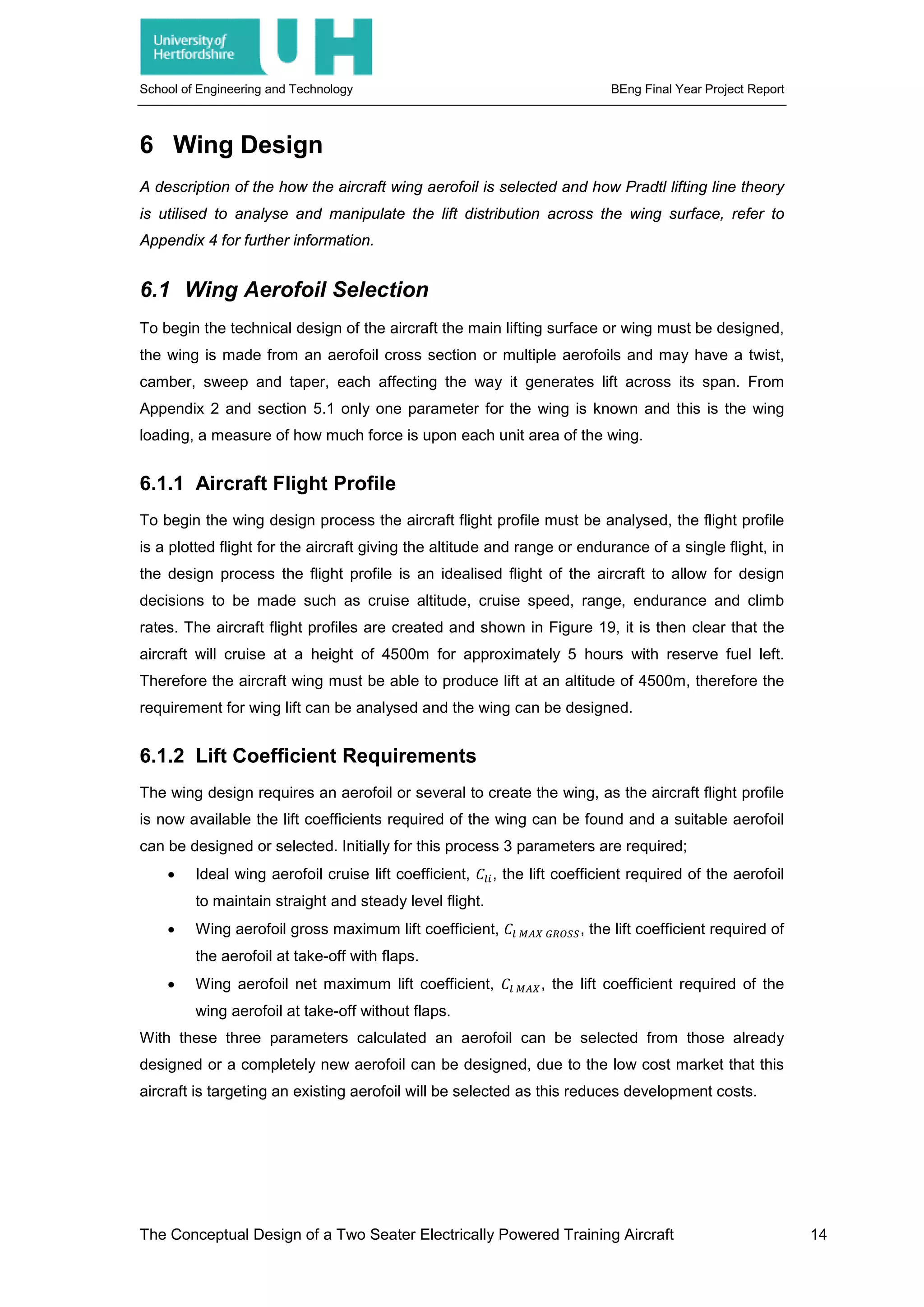
Graph 1 - Wing Lift Distribution Comparison .............................................................................. 17
Graph 2 - Comparison of Component Drag at Cruise................................................................. 20
Graph 3 - Comparison of Component Drag at Take-Off............................................................. 21
Graph 4 - Total Aircraft Drag at 4000m....................................................................................... 21
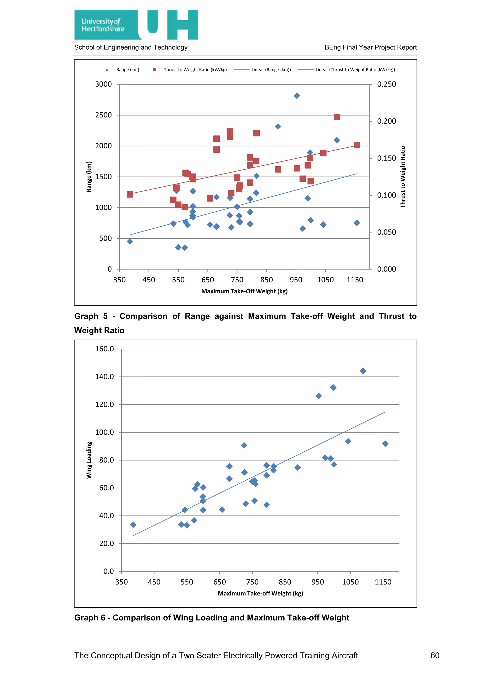
Graph 5 - Comparison of Range against Maximum Take-off Weight and Thrust to Weight Ratio
..................................................................................................................................................... 60
Graph 6 - Comparison of Wing Loading and Maximum Take-off Weight ................................... 60
Graph 7 - Coefficient of Drag against Coefficient of Lift for NACA 652-415 ............................... 65
Graph 8 - Pitching Moment Coefficient against Coefficient of Lift for NACA 652-415 ................ 65
Graph 9 - Coefficient of Lift against Angle of Attack for NACA 652-415..................................... 66
Graph 10 - Lift/Drag Ratio against Angle of Attack for NACA 652-415....................................... 66
Graph 11 - Base Wing Lift Distribution – CL=0.5121 .................................................................. 68
Graph 12 - Final Wing Lift Distribution – CL=0.4793................................................................... 69
Graph 13 - Take-Off Ground Distance........................................................................................ 70
Graph 14 - Comparison of Aircraft Flight Stage Energy Usage.................................................. 70
The Conceptual Design of a Two Seater Electrically Powered Training Aircraft
x](https://image.slidesharecdn.com/0442df0a-d8dc-4f9c-9b24-9e5eae2820ed-160330152913/75/JOHNSON_BENJAMIN_11379847_Report-11-2048.jpg)

![School of Engineering and Technology BEng Final Year Project Report
2 Subject Review
2.1 Market Analysis
For the initial development of any product an investment must be made, this investment is
time and money. The return from this investment is generally money or knowledge and
therefore a market or sector must be identified in which the product will fill a niche. This target
market sets the product aside and makes it desirable therefore offering a return on the
investment, the larger the target or the more important the larger the return. Therefore the
initial stage of any development project is the identification of the market.
2.1.1 Global Warming
It is widely acknowledged that global warming is having a negative impact upon the planet,
the problems caused by rising sea levels and changing climate are costing organisations both
time and money. To stop these problems global warming must be stopped or at least slowed,
this can only be accomplished through massive innovation across all sectors. The most
accepted cause of global warming is the increase in greenhouse gases and the ‘greenhouse
effect’, the increase in the blanketing of the earth by gases which trap heat within the Earth’s
atmosphere which would otherwise be radiated into space. Without this effect Earth would not
be able to support life; however man’s effect upon the atmosphere has increased the amount
of greenhouse gases and caused the atmosphere to retain too much heat therefore warming
the planet. The Intergovernmental Panel on Climate Change stated that; “Continued emission
of greenhouse gases will cause further warming and long-lasting changes in all components
of the climate system, increasing the likelihood of severe, pervasive and irreversible impacts
for people and ecosystems. Limiting climate change would require substantial and sustained
reductions in greenhouse gas emissions which, together with adaptation, can limit climate
change risks.” [1] The currently recognised effects associated with climate change are;
“Glaciers have shrunk, ice on rivers and lakes is breaking up earlier, plant and animal ranges
have shifted and trees are flowering sooner…loss of sea ice, accelerated sea level rise and
longer, more intense heat waves.” [2] However, other unknown effects may be seen which
haven’t been predicted including economic and social effects.
The main gases that contribute to the greenhouse gases are; water vapour, Carbon Dioxide,
Methane, Nitrous Oxide and Chlorofluorocarbons. Each of these gases has a particular effect
upon the Earth’s atmosphere and each come from a particular source:
• Water Vapour; the most abundant greenhouse gas, increases as the Earth’s
atmosphere warms but does not actively effect global warming itself.
• Carbon Dioxide; produced by respiration, the burning of fossil fuels and certain
natural events such as volcanic eruptions is the most stable and therefore most
The Conceptual Design of a Two Seater Electrically Powered Training Aircraft 2](https://image.slidesharecdn.com/0442df0a-d8dc-4f9c-9b24-9e5eae2820ed-160330152913/75/JOHNSON_BENJAMIN_11379847_Report-18-2048.jpg)
![School of Engineering and Technology BEng Final Year Project Report
persistent greenhouse gas. Humans have increased the concentration of Carbon
Dioxide in the atmosphere by 33% since 1760.
• Methane; produced by human activities as well as natural sources, is a more
problematic greenhouse gas, however is in much less abundance.
• Nitrous Oxide; is produced by burning fossil fuels and using commercial and organic
fertilizers.
• Chlorofluorocarbons; are the only gas in the atmosphere that are entirely of human
creation, as well as being a greenhouse gas they destroy the ozone layer causing
more of the suns radiation to heat the atmosphere.
To combat the heating of the atmosphere and the increases in greenhouse gases much of
the research and development in industry has been aimed at reducing the use of fossil fuels.
This has either been through using renewable or sustainable energy sources, creating
recyclable products or increasing the efficiency of existing systems. For the European aviation
industry the European Commission released a report entitled; Flightpath 2050 Europe’s
Vision for Aviation, stating; “Environmental protection has been and remains a prime driver in
the development of air vehicles and new transport infrastructure. In addition to continuously
improving fuel efficiency, the continued availability of liquid fuels, their cost impact on the
aviation sector and their impacts on the environment have been addressed as part of an
overall fuel strategy for all sectors.” [3].
This report lays out the European Commission’s goals for the aviation industry in 2050: [3]
• In 2050, technologies and procedures available allow a 75% reduction in CO2
emissions per passenger kilometre to support the Air Transport Action Group (ATAG)
target, and a 90% reduction in nitrogen oxide (NOx) emissions. The perceived noise
emission of flying aircraft is reduced by 65%. This is relative to the capabilities of
typical new aircraft in 2000.
• Aircraft movements are emission-free when taxiing.
• Air vehicles are designed and manufactured to be recyclable.
• Europe is established as a centre of excellence on sustainable alternative fuels,
including those for aviation, based on a strong European energy policy.
• Europe is at the forefront of atmospheric research and takes the lead in the
formulation of a prioritized environmental action plan and establishment of global
environmental standards.
2.1.2 Energy Prices
Alongside the problems with atmospheric changes by the increase in greenhouse gases is
the problem presented by the reduction in remaining fossil fuel reserves. “There are an
estimated 1.3 trillion barrels of proven oil reserve left in the world’s major oil fields, which at
present consumption rates will be sufficient to last 40 years…it is likely by then that the
The Conceptual Design of a Two Seater Electrically Powered Training Aircraft 3](https://image.slidesharecdn.com/0442df0a-d8dc-4f9c-9b24-9e5eae2820ed-160330152913/75/JOHNSON_BENJAMIN_11379847_Report-19-2048.jpg)
![School of Engineering and Technology BEng Final Year Project Report
world’s population will be twice as large, more industrialization” [4], this suggests that oil
based fuels cannot be relied upon unless there is a dramatic decrease in the consumption of
oil or more oil is discovered. The reduction in oil and its impending rarity has also driven the
price of oil up, “a barrel that cost $10 in 1998 cost $64 in 2007 and today costs $135” [4] that
is an increase of 1250% in less than 15 years. This increase has massive economic impacts;
the direct impact of rising oil prices is a rise across all forms of fuel created from crude oil, in
JAN 2007 the UK’s average price for a litre of unleaded petrol was 90.8 pence in OCT 2014
this had risen to 126.7 pence [5], over the same period the price of Jet fuel rose from $50 a
barrel to $100 (Figure 1) this is an 100% increase in fuel costs for aircraft operators.
Figure 1 - Jet Fuel and Crude Oil Price - [6]
However the increased price of fuel is not the only effect, increased fuel prices increases the
cost of using machinery to harvest crops, this in turn increases the price farmers charge for
their crop and the price the final vendor charges for the product. In the aerospace industry the
increased cost of aviation fuel increases the cost of the flight, this increased cost is reflected
as an increase in ticket price, charter cost or freighter charges. These in turn can lead to
customers seeking alternate options to those given by the aerospace industry, due to the
relatively higher cost the industry becomes less popular and profits fall. Alongside services
provided by the aerospace industry its pilots must also be trained, as simulation is not
completely true to reality, training and flying hours must be maintained on an airframe, this
means that pilots must regularly fly, this requires fuel and therefore if fuel costs more it
increases the cost of pilots maintaining their qualifications. The same approach applies to
training new pilots, for a Private Pilot’s License it’s expected that between 45 and 60 hours
flying is required, therefore for a Cessna 152 flying 45 hours it will use approximately 1518.75
litres of fuel, as a Cessna 152 uses MOGAS, unleaded petroleum, at the current price in fuel
alone the PPL costs £1924.26 a fuel cost increase of 10 pence increases the total PPL fuel
cost by £151.87 a 7.3% increase. The Cessna is a relatively typical training aircraft but 45
hours is the minimum time required it can typically take up to 60 hours to complete the PPL
and these costs increase relatively. These costs increase massively as the aircraft fuel
The Conceptual Design of a Two Seater Electrically Powered Training Aircraft 4](https://image.slidesharecdn.com/0442df0a-d8dc-4f9c-9b24-9e5eae2820ed-160330152913/75/JOHNSON_BENJAMIN_11379847_Report-20-2048.jpg)
![School of Engineering and Technology BEng Final Year Project Report
consumption increases especially with commercial pilot training and airline transport pilot
(ATP) training requiring a minimum of 1500 hours flying, in a Boeing 767 this equates to
8176500 litres of fuel used, at a cost of 41 pence per litre overall costs £3,352,365, a 10
pence increase in jet fuel would cost an extra £817,650. This assumption is not entirely valid
however; if fuel prices could be lowered or a sustainable suitable, cheaper alternative to
current fuels found, this massive cost to the aerospace industry could be lowered
substantially.
2.1.3 Electric Energy
A widely recognized alternative to fossil fuels is electrical energy; generated from burning
fossil fuels, nuclear fission or fusion, solar energy harvesting or chemical reaction, electrical
energy can be suited to most applications that a fossil fuel is currently the only solution.
Energy is invaluable to everyone, it is required for all of life but it can be quantified, stored and
sold, the form that it is sold in can be more or less valuable to a customer and so energy
prices are varied. This is due to the differences in energy density for different storage
methods, three of the most recognized forms of energy are Oil, Natural Gas and Coal, these
energy forms are then refined and used or transferred into a different more usable energy
form. However each of these energy forms must be mined or harvested, due to the value of
the energy being harvested these sites are often the focus of huge contest from company to
country level. As can be seen from Figure 2 the location of oil is focused in several places,
this presents a problem for those countries that rely on oil but have either no or little oil
themselves; this problem is energy security and a lack of. Fossil fuels by their very nature are
only found in large quantities in fixed locations; however renewable energy sources tend to be
available to all countries. Electrical energy can be generated in many different ways and
therefore offers a high energy security as long as the ability to generate it is available; this
makes it a desirable form of energy as, along with its high security, it also has many uses.
Figure 2 - Crude Oil Worldwide Distribution - [7]
Electrical energy however is currently hard to store, 1 litre of unleaded petrol has
approximately 8.5 kWh of energy in it [8], and an average sized car battery can store around
2 kWh. This means that to store the same amount of energy on an aircraft that’s uses fuel
The Conceptual Design of a Two Seater Electrically Powered Training Aircraft 5](https://image.slidesharecdn.com/0442df0a-d8dc-4f9c-9b24-9e5eae2820ed-160330152913/75/JOHNSON_BENJAMIN_11379847_Report-21-2048.jpg)
![School of Engineering and Technology BEng Final Year Project Report
using car batteries you would need around 4.25 times the fuel capacity in batteries. A Cessna
152 has a fuel capacity of 98 litres meaning that it would require 416.5 car batteries for the
same quantity of energy, along with this batteries will only typically last 12 to 15 years unlike a
fuel tank which unless damaged will last the aircraft lifetime [9]. However an engine specific
fuel consumption of anything less than 100% will mean that an engine isn’t turning all the
available energy in the fuel into power, thus it is storing fuel that isn’t converted into
propulsive force. A typical car engine has an SFC of 30% to 40% [10] meaning that less than
half of the stored energy is transferred into power, where as an electric motor has an
efficiency of around 80%-90% meaning that the energy storage is around 4 times the size
when converting to electrical energy but the motor efficiency is double so only half the energy
is required.
Most importantly however the use of electrical energy by motors produces zero tail pipe
emissions, therefore if the electricity is generated in a zero emission way the whole cycle can
have zero effect upon the atmosphere. The tail pipe emissions are not the only form of
pollution caused by a fossil fuel engine, noise has always been an issue whenever aircraft are
concerned, be it expanding airports or low flying aircraft the noise from a large or particularly
loud aircraft can cause problems. Along with the disruption the noise also represents
inefficiency, the energy used to create the noise must come from the fuel used by the engine
and thus again the engine is not running at 100% efficiency. Electrical motors transfer energy
in a much more efficient manner, generally on a small motor the only sound heard is that of
the bearings on the main shaft and the machine that is attached to the motor. On larger
motors these do become more apparent along with other noises but they are still much
quieter than relative conventional fossil fuel engines.
2.2 Electric Aircraft
Currently compared to conventional aircraft, successful electrical aircraft are few and far
between, however the concept has been explored since 1884. The La France airship was the
first aircraft to fly using an electric motor and the first fully controlled flight of any aircraft, the
flight lasted approximately 23 minutes and the aircraft flew 8 kilometres returning to the start
point it had left from. [11] The first flight of a manned electrical aeroplane was on 21 OCT
1973 with the flight of the MB-E1; it flew for 9 minutes and 5 seconds and marked the first
ever manned flight by a solely electric powered aircraft. [12] 1979 marked the first flight of a
solar powered manned aircraft, that being the flight of the Mauro Solar Riser, this flight
covered 800m at heights of around 3m. [13] The next achievement marked by an electrically
powered aircraft was that set by the NASA Environmental Research Aircraft and Sensor
Technology Program (ERAST), the Pathfinder, Pathfinder Plus, Centurion and Helios were
solar powered unmanned aircraft and through their research, development and flights set the
altitude records for solar powered, electric powered, propeller driven and FAI class U-1.d
aircraft. [14] Since these achievements and advancements in electric propulsion and storage
The Conceptual Design of a Two Seater Electrically Powered Training Aircraft 6](https://image.slidesharecdn.com/0442df0a-d8dc-4f9c-9b24-9e5eae2820ed-160330152913/75/JOHNSON_BENJAMIN_11379847_Report-22-2048.jpg)
![School of Engineering and Technology BEng Final Year Project Report
technologies electrical aircraft have become more abundant with several being available as
kit aircraft for private flying. The most applicable to this project is the E-FAN 2.0 and E-FAN
4.0 shown below however others can be found in Appendix 1:
2.2.1 E-FAN 2.0
Description: “It is as clean as a butterfly and hums like a bee: with a 600-kilogram weight
and maximum speed of 160 km/h, E-Fan is the first aircraft with fans to have fully electric
propulsion. The plane has zero carbon dioxide emissions in flight and is significantly quieter
than a conventionally powered aircraft. Lower noise levels of electric propulsion would
potentially benefit airport operations by allowing extended flight operation times and therefore
allowing increases in air traffic.” [15]
Mission: A fully electrically-powered aviation training aircraft
Weight: 600kg
Power Plant: 2x 30kW Electric Ducted fans
Energy Storage: 2x 250V Lithium Ion Polymer Batteries made by KOKAM
Figure 3 - E-FAN 2.0 - [15]
2.2.2 E-FAN 4.0
Description: “The 2.0 version will be followed by the E-Fan 4.0, a four-seater plane targeted
for full pilot licensing and the general aviation market. A company wholly owned by Airbus
Group, named Voltair SAS, will develop, build and offer service for the two E-Fan production
versions. The final assembly facilities will be located at Bordeaux-Mérignac Airport in the
framework of French government-backed projects for the country’s future industrialisation,
called La Nouvelle France Industrielle.” [15]
Mission: 4 Seater Training Aircraft
The Conceptual Design of a Two Seater Electrically Powered Training Aircraft 7](https://image.slidesharecdn.com/0442df0a-d8dc-4f9c-9b24-9e5eae2820ed-160330152913/75/JOHNSON_BENJAMIN_11379847_Report-23-2048.jpg)
![School of Engineering and Technology BEng Final Year Project Report
Figure 4 - E-FAN 4.0 - [15]
2.3 Training Aircraft History
Ever since man first took flight it has been known the pilots need training and that an aircraft
specially designed for this purpose will allow a pilot to be trained faster and more effectively,
some recognize the first trainer aircraft as the Curtiss JN-4D Jenny produced for the US Army
in 1915 it used the modern technologies of current aircraft and based them in a robust and
easily adaptable structure, its estimated that 95% of all WW1 Allied pilots trained in a JN-4.
During WW2 and with further advances in aerodynamic understanding and technology aircraft
such as the de Havilland Tiger Moth and North American T-6 Texan emerged, both were
primary trainers showing simple but robust structures with predictable flying characteristics
and cheap maintenance. After WW2 and the invention of the jet engine and its application in
aircraft there was a split into prop and jet trainers, with primary learning staying with propeller
aircraft due to their relatively lower maintenance costs and slower, more easily controlled
flying characteristics. With the huge spending in technology and defence during the Cold War
many new ideas and innovations came to life as company budgets were near unlimited,
nearly any imaginable aircraft configuration was designed, created and tested creating a huge
array of aircraft which all required more training and research. In line with the advances in
military aviation after WW2 and still to the present civil aviation, particularly passenger flight
advanced tremendously. Older air frames and old technologies became available to the
civilian market as military organizations modernized and looked to sell older aircraft, these
aircraft were then used by entrepreneurs to advance airlines and freight businesses, as these
companies became more proliferate; aircraft manufacturers began to design aircraft
especially for them. The advances and the increased spending in the aviation industry also
lead to new methods and decreased costs in manufacturing which allowed smaller companies
with niche markets to develop.
The Conceptual Design of a Two Seater Electrically Powered Training Aircraft 8](https://image.slidesharecdn.com/0442df0a-d8dc-4f9c-9b24-9e5eae2820ed-160330152913/75/JOHNSON_BENJAMIN_11379847_Report-24-2048.jpg)
![School of Engineering and Technology BEng Final Year Project Report
3 Concept Generation
A description of how an initial concept for the aircraft is created and how a concept is selected
to be advanced through the design process, also contained within this chapter is a description
of the design process to be used through the aircraft concept development, refer to Appendix
3 for a full list of created concepts and their analysis.
To begin the design process a view for the aircraft is created, this gives the designer a view of
the final product and can help to rectify discrepancies in the theoretical design; therefore it is
imperative that throughout the design process the sketch or multiple sketches are updated in
line with any changes made to the design. However the designer must first produce an initial
sketch as a start point for the aircraft, this is done by creating and analysing several different
designs and choosing the most favourable. In this instance 12 initial concepts are created and
analysed with concept 6, Figure 5 being taken forward through the design process.
Figure 5 - Final Design Concept Sketch
3.1 Development Process
The development process adopted is a combination taken from [16] and [17], with the
theoretical methods used taken from [16] and a basis for the development process taken from
[17]. This development process will take the concept aircraft from initial concept to full 3D
model with an in depth analysis of critical characteristics and flying ability.
The Conceptual Design of a Two Seater Electrically Powered Training Aircraft 9](https://image.slidesharecdn.com/0442df0a-d8dc-4f9c-9b24-9e5eae2820ed-160330152913/75/JOHNSON_BENJAMIN_11379847_Report-25-2048.jpg)
![School of Engineering and Technology BEng Final Year Project Report
The development process is shown below:
Figure 6 - Design Development Process - [17]
This design development process will be used to develop the concept previously shown into a
full specification and final assembly; however it does not mark the end of the development
process. Further analysis into the structure, aerodynamic properties and flying qualities using
CFD, FEA and other simulations will be used to fully understand and improve the aircraft
characteristics which may not have shown during the design process. After this manufacturing
limitations will have to be assessed and finally several prototype aircraft would have to be
built and tested to verify the entire process. Even after the aircraft is manufactured however,
advances in technology and manufacturing may allow further development of the aircraft
technologies, and different but similar requirements may encourage development of different
aircraft variations upon the same initial design.
First Estimate
• MTOW
• Wing Area
• Drag Estimate
• Thrust at Cruise
Fuselage Design Wing Design First Layout Sketch
Second Estimate
• Drag
• Thrust Centre of Gravity Analysis Tail Design Second Layout Sketch
Third Estimate
• Drag
• Thrust Landing Gear Design Structural Design Drag and Thrust Analysis
Control Surface Design Third Layout Sketch
Final Weight and Centre of
Gravity
Final Performance
Analysis
Final Stability and Control
Analysis
Final Specification Fianl Assembly
The Conceptual Design of a Two Seater Electrically Powered Training Aircraft 10](https://image.slidesharecdn.com/0442df0a-d8dc-4f9c-9b24-9e5eae2820ed-160330152913/75/JOHNSON_BENJAMIN_11379847_Report-26-2048.jpg)
![School of Engineering and Technology BEng Final Year Project Report
6.1.3 Wing Aerofoil Cruise Lift Coefficient, 𝑪𝑪𝒍𝒍𝒍𝒍
The calculation of 𝐶𝐶𝑙𝑙𝑙𝑙 requires three already chosen parameters, maximum take-off weight,
wing loading and aircraft cruise speed, these two can be input into the general lift equation
and 𝐶𝐶𝑙𝑙𝑙𝑙 can be calculated. Therefore using the aircraft cruise speed of 110 knots, mass of
750kg, wing area of 14m
2
and a cruise altitude of 4500m it is found that the 𝐶𝐶𝑙𝑙𝑙𝑙 required is
approximately 0.5.
6.1.4 Wing Aerofoil Gross Maximum Lift Coefficient, 𝑪𝑪𝒍𝒍 𝑴𝑴𝑴𝑴𝑴𝑴 𝑮𝑮𝑮𝑮𝑮𝑮𝑮𝑮𝑮𝑮
The calculation of 𝐶𝐶𝑙𝑙 𝑀𝑀𝑀𝑀𝑀𝑀 𝐺𝐺𝐺𝐺𝐺𝐺𝐺𝐺𝐺𝐺 again requires parameters lain out in section 6.1.3, however for
this calculation the stall speed is used instead of cruise speed, this gives the worst flying
condition required of the wing and thus the greatest amount of lift it must produce with flaps.
Using a stall speed of 45 knots, mass of 750kg, wing area of 14m
2
and altitude of 0m it is
found that the 𝐶𝐶𝑙𝑙 𝑀𝑀𝑀𝑀𝑀𝑀 𝐺𝐺𝐺𝐺𝐺𝐺𝐺𝐺𝐺𝐺 required is approximately 1.87.
6.1.5 Wing Aerofoil Net Maximum Lift Coefficient, 𝑪𝑪𝒍𝒍 𝑴𝑴𝑴𝑴𝑴𝑴
The calculation of 𝐶𝐶𝑙𝑙 𝑀𝑀𝑀𝑀𝑀𝑀 is the calcualtion of the maximum lift coefficient of the wing without
the effect of flaps, this is calculated by analysing the lift coefficient of similar aircraft with flaps
and substituting this from the 𝐶𝐶𝑙𝑙 𝑀𝑀𝑀𝑀𝑀𝑀 𝐺𝐺𝐺𝐺𝐺𝐺𝐺𝐺𝐺𝐺, a general aviation aircraft of this weight generally
has a ∆𝐶𝐶𝑙𝑙 𝐻𝐻𝐻𝐻𝐻𝐻 of around 0.7 [16] and therefore the aircraft 𝐶𝐶𝑙𝑙 𝑀𝑀𝑀𝑀𝑀𝑀 𝐺𝐺𝐺𝐺𝐺𝐺𝐺𝐺𝐺𝐺 is approximately 1.17.
With this calculation complete all required lift coefficients have been found for the aircraft and
thus an aerofoil can be selected. For benefits in manufacturing and development the wing will
consist of a single aerofoil profile across its length therefore reducing development time and
costs and reducing manufacturing complexity, time and cost.
6.1.6 Aerofoil Selection
When selecting the aerofoil there are several parameters that must be considered;
• Lift coefficients, 𝐶𝐶𝑙𝑙𝑙𝑙, 𝐶𝐶𝑙𝑙 𝑀𝑀𝑀𝑀𝑀𝑀 𝐺𝐺𝐺𝐺𝐺𝐺𝐺𝐺𝐺𝐺 and 𝐶𝐶𝑙𝑙 𝑀𝑀𝑀𝑀𝑀𝑀, all of which are calculated.
• Drag coefficient, 𝐶𝐶𝑑𝑑 𝑚𝑚𝑚𝑚 𝑚𝑚, the minimum drag condition of the aerofoil at the ideal lift
coefficient, this must be as small as possible to reduce the amount of drag produced
by the wing at cruise.
• Pitching moment coefficient, 𝐶𝐶𝑚𝑚0, the pitching moment of the aerofoil at 0° alpha, this
must be as small as possible to reduce the pitching moment produced by the wing at
cruise and thus reduce horizontal stabiliser size.
• Stall angle, ∝𝑆𝑆, the stall angle of the aerofoil at both 0° and 60° flap extension, this
must be as high as possible therefore allowing lift at higher angles of attack and
increasing flight safety.
• Stall quality, the qualities of the aerofoil after the stall, due to the requirement for the
aircraft to be a docile primary trainer and general private aviation aircraft the stall
The Conceptual Design of a Two Seater Electrically Powered Training Aircraft 15](https://image.slidesharecdn.com/0442df0a-d8dc-4f9c-9b24-9e5eae2820ed-160330152913/75/JOHNSON_BENJAMIN_11379847_Report-31-2048.jpg)
![School of Engineering and Technology BEng Final Year Project Report
quality of the aerofoil must be moderate or soft to reduce the danger of the stall upon
the aircraft flight.
As stated already the aerofoil will be selected from those already designed, these are
available in several texts such as [18], the available aerofoils can then be placed into a table
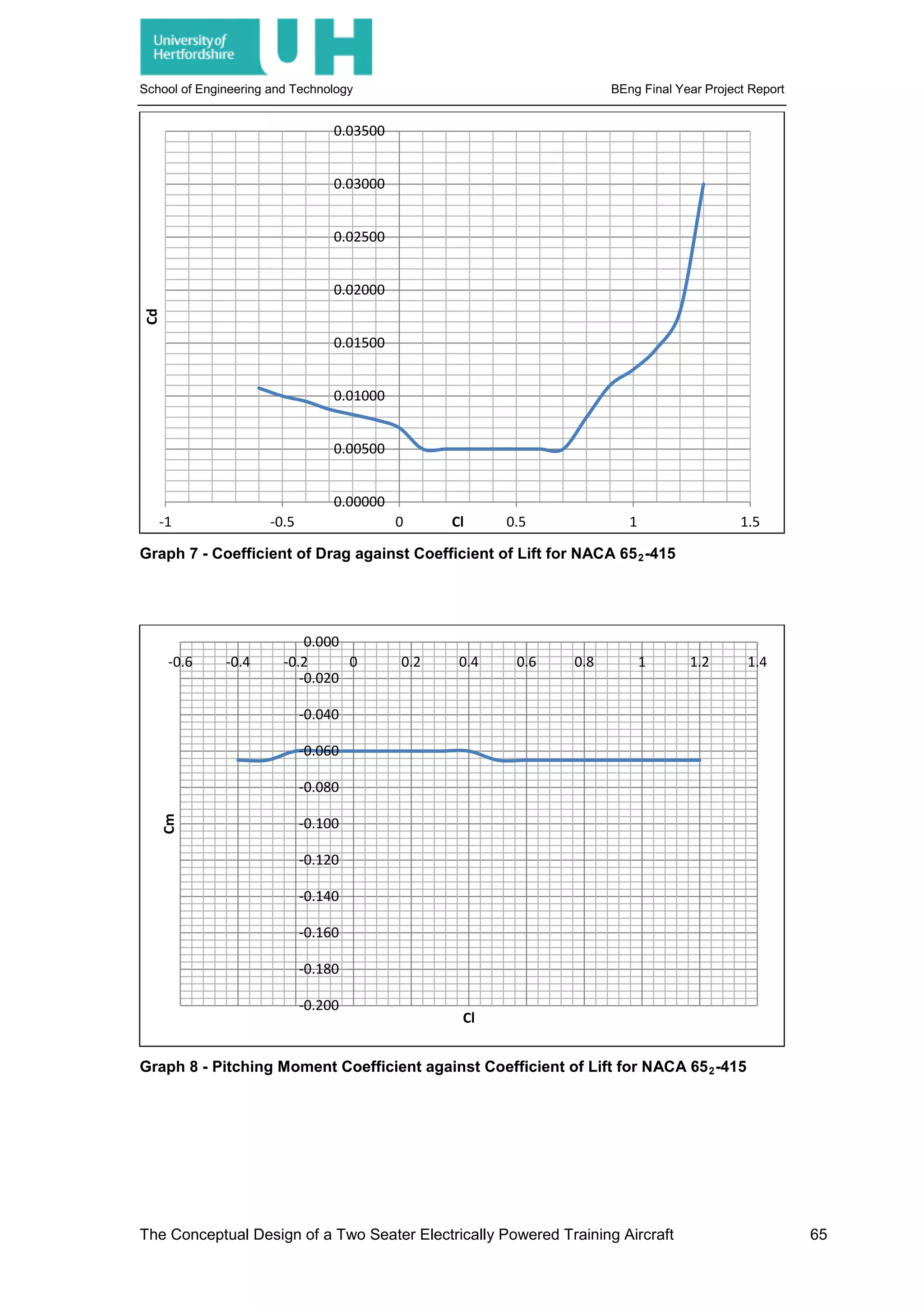
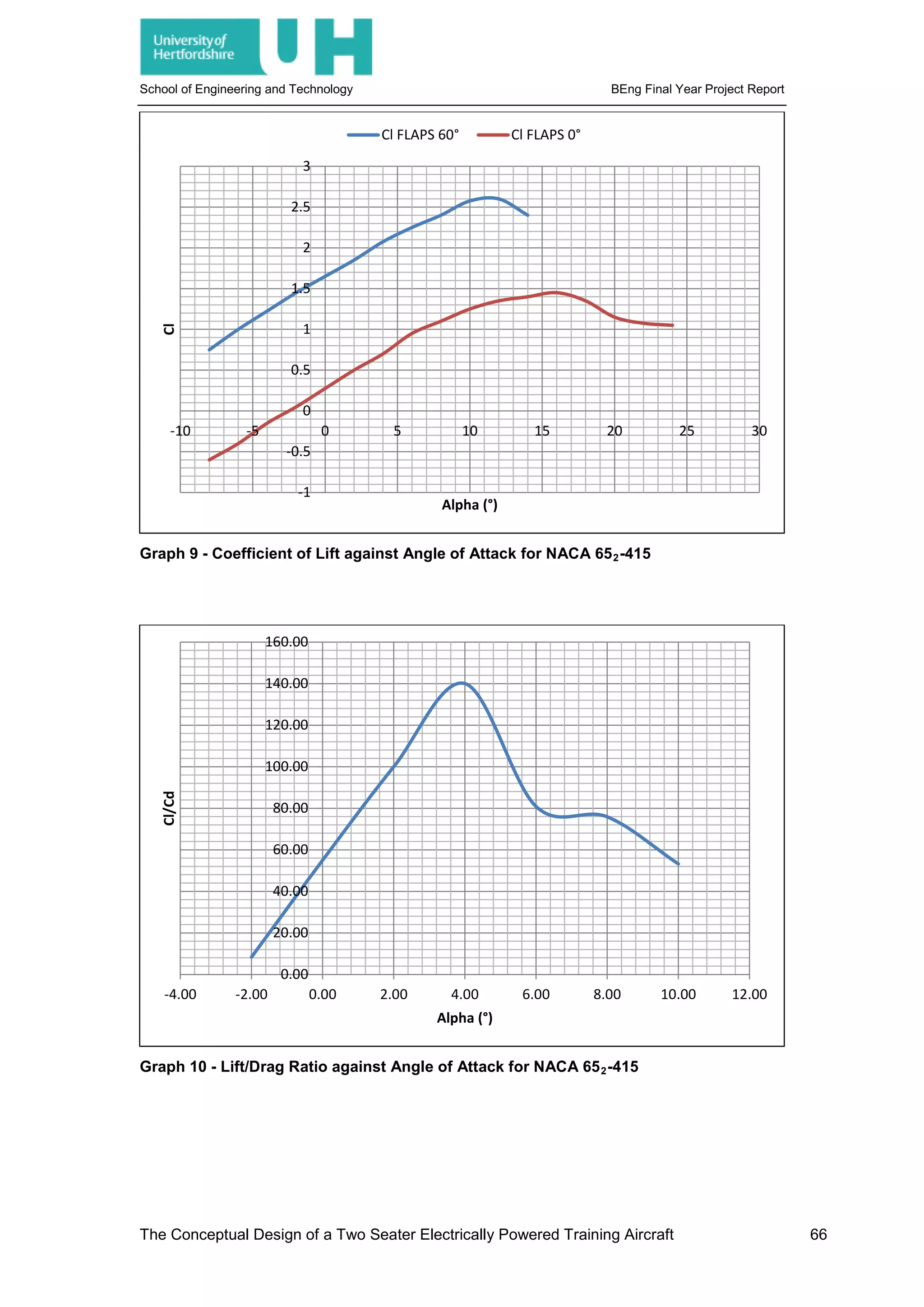
and analysed for their suitability. It is found that NACA Profile 652-415 is the most suitable
due to its appropriate lift coefficients, low drag coefficients, low pitching moment, high stall
angles and soft stall qualities. The aerofoil graphs are shown in Graph 7, Graph 8, Graph 9
and Graph 10.
6.2 3D Wing Design
With the selection of an aerofoil the wing can be designed, to analyse the 3D properties of the
wing Pradtl lifting line theory is used in MatLab, Code 1, Pradtl’s lifting line theory is generally
accurate and offers an excellent insight into how a lifting surface will perform for a given set of
parameters. The base wing is then turned into several variables, Code 2, and an iterative
process can be started to maximise the efficiency of the wing and make sure it’s suitable for
its intended application.
As can be seen from Graph 11 the lift distribution across the wing is non-elliptical, this has
several non-desirable consequences but most importantly for this aircraft the non-elliptical
distribution will promote tip stall, this condition is when the tip of the wing stalls at the same
time as, or before, the root of the wing. This causes a loss of roll control and makes recovery
from the stall more difficult, in a training aircraft this condition is entirely undesirable and
therefore must be designed out. There are several ways this condition can be designed out,
these include the introduction of taper, twist, sweep and a change in aspect ratio, as the
aspect ratio is fixed and sweep is unnecessary due to the sweep being more important in
transonic and supersonic aircraft the change in twist and taper must be analysed.
6.2.1 Taper Ratio
As the taper ratio increases the lift generated at the tip of the aerofoil increases, however so
does the lift across the entire surface, it can be seen that the rectangular wing has a good lift
distribution where as a wing with a taper ratio of 0 has a very undesirable wing lift distribution
for a training aircraft.
6.2.2 Twist
As the twist of the wing increases the lift generated at the tip of the aerofoil decreases,
however so does the lift across the entire surface, it can be seen that as the wing increases
twist the lift distribution becomes more elliptical and thus more suitable, however this is at the
expense of lift.
The Conceptual Design of a Two Seater Electrically Powered Training Aircraft 16](https://image.slidesharecdn.com/0442df0a-d8dc-4f9c-9b24-9e5eae2820ed-160330152913/75/JOHNSON_BENJAMIN_11379847_Report-32-2048.jpg)

![School of Engineering and Technology BEng Final Year Project Report
Figure 9 - Induced Drag - [19]
This induced drag factor increases and decreases with the amount of lift created by the
aerofoil and similarly to parasitic drag decreases with altitude, however due to the high
amount of lift required when an aircraft is flying slowly induced drag is very high when an
aircraft is at take-off and can cause dangerous conditions at the stall.
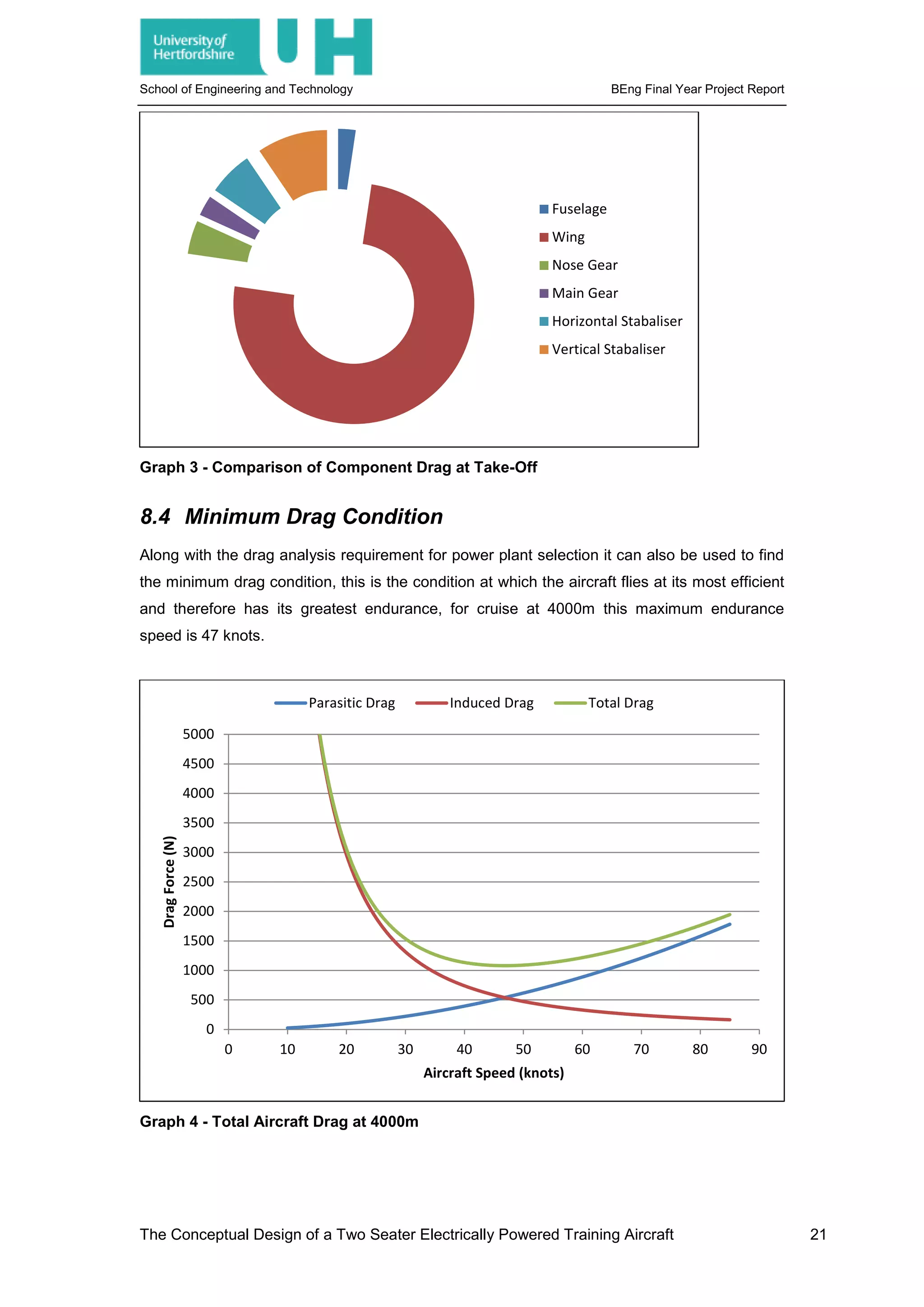
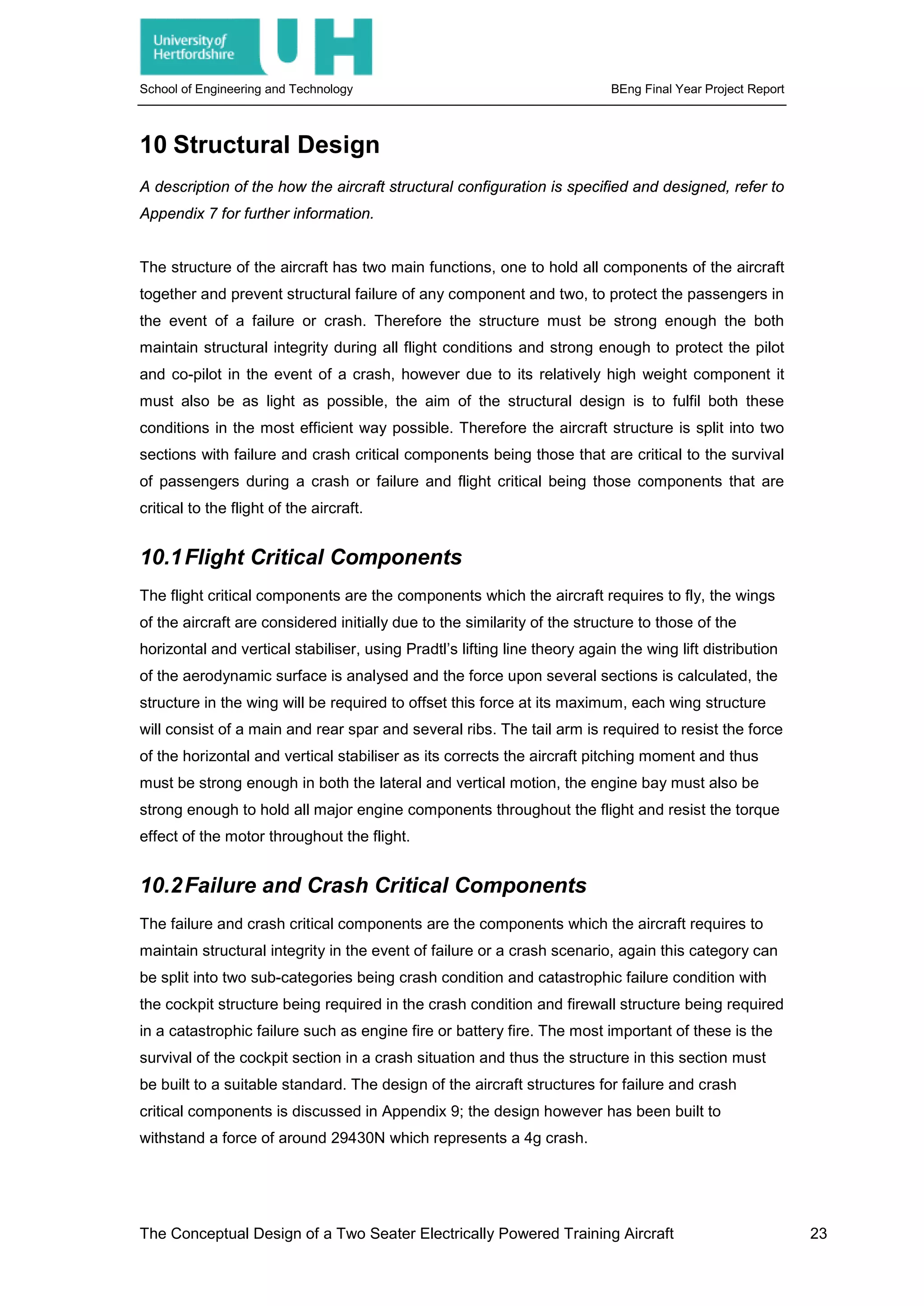
8.3 Total Aircraft Drag
With the calculation of parasitic and induced drag, the total drag for the aircraft can be
analysed for the most extreme aircraft conditions, this is calculated for both the aircraft take-
off condition and the aircraft cruise condition giving the results shown below in; Graph 2 and
Graph 3.
Graph 2 - Comparison of Component Drag at Cruise
Fuselage
Wing
Nose Gear
Main Gear
Horizontal Stabaliser
Vertical Stabaliser
Incident
airflow
Lift
Net direction of airflow past aerofoil
Net direction of airflow
past aerofoil
Incident
airflow
Induced drag
Lift
The Conceptual Design of a Two Seater Electrically Powered Training Aircraft 20](https://image.slidesharecdn.com/0442df0a-d8dc-4f9c-9b24-9e5eae2820ed-160330152913/75/JOHNSON_BENJAMIN_11379847_Report-36-2048.jpg)
![School of Engineering and Technology BEng Final Year Project Report
9 Landing Gear Design
A description of the how the aircraft landing gear configuration is specified and designed,
including the calculation of the static and dynamic loads upon each wheel and the
specification of brake systems and tyres, for further information refer to Appendix 7.
The landing gear for an aircraft is the components on which the aircraft stands, designed to
hold the aircraft off the ground for engine or propeller clearances and a means of landing the
aircraft without damaging aircraft components, landing gear may be of many forms, with
wheels being common but other forms such as skids, skies, floats or keels can also be used.
The aircraft has been chosen to use a tricycle undercarriage arrangement utilising a fixed
wheeled landing gear configuration, the landing gear design process begins with the ranking
of the landing gear requirements so that the worst condition for the landing gear can be
identified.
The propeller clearance is the worst case scenario for the undercarriage and thus the
propeller clearance will dictate the length of the undercarriage, the aircraft landing gear height
is calculated as 0.77m from the aircraft fuselage and 1.36m from the aircraft centreline. With
the height of the landing gear selected the aircraft track and base must be defined, the
landing gear track is the distance between the main gear laterally and the base is the distance
between the main and nose or tail gear. For an aircraft with tricycle landing gear around 85%
of the aircraft weight is required on the main gear and to maintain control during the taxi
around 15% of the aircraft weight is required on the aircraft nose gear [16]. The main gear
position is found to be at 0.2m behind the foremost aircraft centre of gravity, using the tricycle
undercarriage loading requirement force on the main gear is found to be 6475N and the force
at the nose gear is found to be 883N, it is found that the aircraft requires a base of 1.67m
placing the main gear at 2.66m from the nose and the main gear 1m from the nose. However
the landing gear must be specified for landing, with the downward velocity of the aircraft
causing the dynamic loading upon the aircraft to be greater than the static loading. To
account for this velocity component a factor of 1.5 – 2 can be applied to the force upon the
landing gear and thus the maximum expected loading upon each wheel is shown in Table 7,
again for decreased cost and development time an existing component is selected, specified
in Appendix 7a and Appendix 7b. The landing gear is also used for braking during landing.
The aircraft will land between 54knots and 45 knots, causing at maximum 144583Nm of
Kinetic Energy per wheel, the brakes will consist of two Kevlar based brake pads clamping
onto a steel brake disc by means of a hydraulic brake system.
The Conceptual Design of a Two Seater Electrically Powered Training Aircraft 22](https://image.slidesharecdn.com/0442df0a-d8dc-4f9c-9b24-9e5eae2820ed-160330152913/75/JOHNSON_BENJAMIN_11379847_Report-38-2048.jpg)
![School of Engineering and Technology BEng Final Year Project Report
14 Stabiliser Design, Control Surface Design and
Stability and Control Analysis
A description of the how the aircraft stabilisers are designed and an analysis of the aircraft
stability, refer to Appendix 8 for further information.
14.1Centre of Gravity
An aircraft’s centre of gravity is the datum from which all calculation of stability comes;
therefore defining an aircraft’s most extreme centre of gravity limits is one of the most
important parts of designing one. If a consumer was to load an aircraft such that the centre of
gravity fell outside the fore or aft limits it could not fly in a stable condition therefore the first
stage in analysing the stability of an aircraft is to find these limits, a process of computing and
analysing the centre of gravity variation for different load cases and conditions that the design
requires. The calculation of the centre of gravity of an aircraft requires only the weight and
location of each component, for a small general aviation aircraft where component weights
are relatively similar each component must be considered as each effect the centre of gravity
greatly.
14.1.1 Centre of Gravity Analysis
To start the design process information gathered during the initial research stages is input into
a table, this table serves as the foundation of the centre of gravity analysis, whenever a
component is updated or changed the table must be updated to account for this, the main
data required is the location and weight of each component, each of the components masses
is multiplied by gravitational acceleration to give weight in newton’s, this is then multiplied by
the distance in each axis to produce a moment in the x, y and z axis for each component in a
more conventional format.
14.2Longitudinal Stability
Longitudinal stability is the stability in the XZ, or longitudinal axis of the aircraft. The main
effectors upon longitudinal stability are the centre of gravity, aerodynamic centre and
horizontal stabiliser. The horizontal stabiliser is a second lifting device used to offset the
moment created by the wings lift about the centre of gravity.
14.3Longitudinal Static Stability
14.3.1 Pitching Moment
Longitudinal stability is defined as; “the tendency of a body (or system) to return to equilibrium
when disturbed.” [20]. The moment created by the wing aerodynamic centre upon the centre
The Conceptual Design of a Two Seater Electrically Powered Training Aircraft 28](https://image.slidesharecdn.com/0442df0a-d8dc-4f9c-9b24-9e5eae2820ed-160330152913/75/JOHNSON_BENJAMIN_11379847_Report-44-2048.jpg)
![School of Engineering and Technology BEng Final Year Project Report
of gravity of the aircraft is called the pitching moment or 𝐶𝐶𝑚𝑚𝑚𝑚𝑚𝑚, as stated this is negated by the
horizontal stabiliser making the aircraft longitudinally statically stable. Therefore for straight
and level, steady flight the pitching moment must be equal to 0.
14.3.2 Stabiliser Moment Arm
From the analysis of the centre of gravity the designing of the horizontal stabiliser can begin,
initially data from the wing and data from the centre of gravity analysis is used alongside the
aircraft design to find the key dimensions, of which the most important are the aerodynamic
centre of the wing, centre of gravity and horizontal stabiliser arm. The centres of gravity
parameters are available from previous analysis; however the wing aerodynamic centre must
be found using a combination of aerofoil data and wing analysis. For a wing the aerodynamic
centre is generally located at 25% of the mean aerodynamic chord however it be found in
aerofoil summary books such as Theory of Wing Sections by [18], this measurement along
with the centre of gravity are non-dimensionalised by the mean aerodynamic chord, the
horizontal stabiliser arm is designed through iteration and physical limitation of the aircraft and
design specification. From this process the tail arm is chosen to be 2.730m placing it at
4.849m from the nose of the aircraft, using an analysis of existing stable aircraft of this type it
is found that for a light general aviation aircraft 𝑉𝑉�ℎis typically 0.3. [16].
14.3.3 Aerofoil Selection
For the aircraft in cruise the horizontal tail lift coefficient is found to be -0.179; this value
allows the designer to fully design the remaining parameters of the horizontal stabiliser. First
an aerofoil section must be chosen for the horizontal stabiliser as it is a lifting surface. There
are several given parameters when designing this lifting surface; the aerofoil must be
symmetrical, this is because it will need to counter pitching moments both nose up and nose
down, it is also desirable for the stabiliser aerofoil to have no pitching moment at its
aerodynamic centre which is a feature of all symmetrical aerofoils. It is also desirable to have
as low a minimum coefficient of drag ,or 𝐶𝐶𝑑𝑑𝑑𝑑𝑑𝑑𝑑𝑑, and as high a stall angle, or 𝛼𝛼𝑠𝑠, as possible.
NACA profile 0009 is chosen in line with these aims and the data for the aerofoil is taken,
Table 11.
14.3.4 Horizontal Stabiliser Design
Again by utilising the Pradtl lifting line tool the horizontal stabiliser is found of to produce the
required 𝐶𝐶𝐿𝐿 at −3.02°
. It must be noted that the sweep angle and taper ratio of the horizontal
stabiliser are selected to be the same as that of the wing, this is to ensure similar benefits of
this lifting surface as that of the wing. However there is no twist upon the horizontal stabiliser,
this is because there is no requirement for elliptical lift distribution.
The Conceptual Design of a Two Seater Electrically Powered Training Aircraft 29](https://image.slidesharecdn.com/0442df0a-d8dc-4f9c-9b24-9e5eae2820ed-160330152913/75/JOHNSON_BENJAMIN_11379847_Report-45-2048.jpg)
![School of Engineering and Technology BEng Final Year Project Report
14.4Longitudinal Dynamic Stability
An aircraft flying in equilibrium that experiences a longitudinal disturbance may experience
two types of motion, Phugoid and Short Period Pitching Oscillation. For an aircraft to be
longitudinally dynamically stable it must be positively damped in both motions, for the aircraft
to have good flying qualities, the combination of damping and natural frequency must be
conducive to reducing the workload upon the pilot. Longitudinal dynamic stability can be
approximated from the aircraft longitudinal equations of motion by considering the effect they
have upon the aircrafts flight. Phugoid motion is described as; “a low frequency, lightly
damped oscillation characterised by a change in forward velocity and pitch angle at nearly
constant incidence.” [21]. Short period pitching oscillation or SPPO is described as; “a short
period heavily damped oscillation characterised by changes in pitch angle and incidence …
with little variation in forward speed”. [22]
14.4.1 Phugoid and Short Period Pitching Oscillation
For the aircraft, the parameters found through the horizontal stabiliser design, centre of
gravity analysis and aerodynamic analyses are applied and the Phugoid and SPPO can be
approximated the following results are obtained and shown in Table 1:
Phugoid SPPO
𝜔𝜔𝑛𝑛 0.277889745 𝜔𝜔𝑛𝑛 6.516564
𝜁𝜁 0.114498306 𝜁𝜁 0.439088
𝑇𝑇 11.38002 𝑇𝑇 0.536587
𝑡𝑡1
2
21.78481518 𝑡𝑡1
2
0.242245
Table 1 - Longitudinal Approximation Results
14.5Elevator Design
The elevators are the control surface used to manoeuvre the aircraft in the pitch about the
lateral axis; they are generally positioned on the trailing edge of the horizontal stabiliser, the
elevator design is dictated by the elevator trim requirement. The horizontal stabiliser has been
designed to keep the aircraft stable in the cruise condition however the horizontal stabiliser
will have to provide different lift values through the flight, as the size of the horizontal stabiliser
on a conventional aircraft cannot be changed through the flight an elevator is employed to
change the horizontal stabiliser lift. Along with the trim requirement a more critical
employment of the elevator is pitch control at low speeds such as at take-off and landing, the
aircraft’s elevator must allow it to change the aircraft’s pitch at take-off to allow take-off
rotation and to stop ground looping.
The Conceptual Design of a Two Seater Electrically Powered Training Aircraft 31](https://image.slidesharecdn.com/0442df0a-d8dc-4f9c-9b24-9e5eae2820ed-160330152913/75/JOHNSON_BENJAMIN_11379847_Report-47-2048.jpg)


![School of Engineering and Technology BEng Final Year Project Report
18.2Performance Comparison
The UH 145-T has higher speeds in both max speed and cruise speed, also of note is the
lower stall speed thus the UH 145-T can fly faster and safer than the Cessna 152, also
allowing it to take-off and land more quickly and more safely than the already very popular
Cessna 152. The UH 145-T is designed to withstand a 20 knot crosswind to that of the
Cessna 152’s 12 knots. The UH 145-T also has a shorter take-off run than that of the Cessna
152, 348m to the Cessna’s 408m, however the Cessna 152 has a higher rate of climb than
the UH 145-T, 218 to 127.17 m/min, this requires that the UH 145-T has a more thorough
performance analysis to evaluate the best angle and rate of the climb for the aircraft. The
Cessna 152 however cruises at 2438.4m to the UH 145-T’s 4000m and thus the UH 145-T
can fly higher in an effort to reduce drag and increase range. The UH 145-T with its designed
battery has a cruise endurance of 6 hours, compared to the Cessna 152’s 3.4 hours with the
standard fuel tanks or 5.4 hours with long range tanks.
18.3Conclusion
To conclude the UH 145-T fulfils the same role as the Cessna 152 however it does so with
improvements in areas such as speed, safety, weight and take-off performance, the UH 145-T
does perform worse in the climb however this must be analysed more thoroughly to ensure
that the aircraft is represented suitably. Both aircraft have similar design features for the same
reasons however the UH 145-T exploits the advantages of these design features to a greater
degree, with placement of the wing crucial giving the pilot a greater degree of visibility, the
most crucial feature for a training aircraft. The aircraft however critically relies upon the fuel
source; if the fuel source is not suitable the aircraft either will not fly or will not fly as far or as
long. As stated in section 13 the battery is required to produce 2324.775 MJ, if the aircraft
cruise was reduced to 3.4 hours to match the Cessna 152 it would require 1510.455 MJ of
energy, therefore the specific energy of the battery is required to be 38.746 MJ/kg for a 6 hour
cruise or 25.17 MJ/kg for a 3.4 hour cruise, from section 2.1.3 it was stated that the energy
density of petrol or MOGAS is 44.4 MJ/kg and therefore for the 6 hour cruise the UH 145-T
requires 66.8 or 43.4 litres of MOGAS respectively, showing that the UH 145-T is more
efficient than the Cessna 152, also as stated in section 2.1.2 the price of the private pilot’s
licence for 45 hours in fuel is around £1924.26, the UH 145-T cost for 45 hours of flying with
an electricity price of 17.41 pence per kilowatt [23] is around £480.59 representing a saving of
around 75% with the bonus of zero fuel emissions created by the aircraft and conformity with
EASA’s flight plan 2050.
The Conceptual Design of a Two Seater Electrically Powered Training Aircraft 48](https://image.slidesharecdn.com/0442df0a-d8dc-4f9c-9b24-9e5eae2820ed-160330152913/75/JOHNSON_BENJAMIN_11379847_Report-64-2048.jpg)
![School of Engineering and Technology BEng Final Year Project Report
19.2Battery Development
The second critical development stage for the aircraft is the battery or fuel source, chosen for
this project was the battery power source, however currently the best batteries for energy
density are lithium-ion polymer batteries, as shown in Figure 17 they have been roughly
doubling in volumetric energy density each year, however the UH 145-T batteries require a
Volumetric Energy Density of 3843874 Wh/l or an Energy Density of 38746.25 Wh/kg which
at double each year would require 14 years to reach which is in the near future, however it is
known that Lithium Ion batteries are reaching their theoretical limit of 620 Wh/l. There has
been research into other batteries, based upon Lithium-Polymers, these again offer increases
in battery volumetric energy density and energy density but will not fulfil the requirements of
the UH 145-T initial 6 hour cruise time, if the flight is brought to a demonstration flight of 30
minutes for an air show the required energy density drops to 398350 Wh/l however this is still
a massive amount compared to current battery technology. It may be viable therefore to
change the power source for the aircraft, using the same format as the current batteries the
UH 145-T could be converted to use an alternative power source such as hydrogen based
technology, using the wings as storage tanks for the fuel and the battery holders as the fuel
cells. This would maintain the aircrafts adherence to the design specification and would still
offer an emission free solution to pilot training.
Figure 17 - Energy Density Increases - [24], [25]
With the advances in technology on the horizon and the commitment of EU countries to the
Flightpath 2050 plan, electrically powered aircraft and electrically powered vehicles in other
sectors will become more popular and more viable. It may be possible that in the near future
the advances in alternative fuels will allow the reduction of fossil fuel based technologies and
the reduction of emissions across the globe. However until this technology is fully proven by
the public and the current problems that plague alternative fuel based vehicles are removed
the fossil fuel based engine will maintain its position as the preferred engine type due to the
benefits in energy density of fossil fuels.
The Conceptual Design of a Two Seater Electrically Powered Training Aircraft 50](https://image.slidesharecdn.com/0442df0a-d8dc-4f9c-9b24-9e5eae2820ed-160330152913/75/JOHNSON_BENJAMIN_11379847_Report-66-2048.jpg)

![School of Engineering and Technology BEng Final Year Project Report
REFERENCES
[1] Intergovernmental Panel on Climate Change, “IPCC Fifth Assessment Synthesis Report -
Approved Summary for Policy Makers,” 2014.
[2] NASA, “NASA Global Climate Change,” [Online]. Available:
http://climate.nasa.gov/causes/. [Accessed 05 NOV 2014].
[3] European Commission, “Flightpath 2050 Europe's Vision for Aviation,” Publications Office
of the European Union, Luxembourg, 2011.
[4] Institution of Mechanical Engineers, “When will oil run out?,” [Online]. Available:
http://www.imeche.org/knowledge/themes/energy/energy-supply/fossil-energy/when-will-
oil-run-out. [Accessed 11 NOV 2014].
[5] PetrolPrices.com, “The Price of Fuel,” 2014. [Online]. Available:
http://www.petrolprices.com/the-price-of-fuel.html#j-1-1. [Accessed 11 NOV 2014].
[6] Platts, “Platts Jet Fuel,” Platts, OCT 2014. [Online]. Available:
http://www.platts.com/jetfuel. [Accessed OCT 2014].
[7] NationMaster, “Energy > Oil > Reserves: Countries Compared,” [Online]. Available:
http://www.nationmaster.com/country-info/stats/Energy/Oil/Reserves. [Accessed 09 DEC
2014].
[8] Alternative Fuels Data Center, “Alternative Fuels Data Center - Fuel Properties
Comparison,” 29 OCT 2014. [Online]. Available:
http://www.afdc.energy.gov/fuels/fuel_comparison_chart.pdf. [Accessed 20 NOV 2014].
[9] U.S Department of Energy, “Benefits and Considerations of Electricity as a Vehicle Fuel,”
[Online]. Available: http://www.afdc.energy.gov/fuels/electricity_benefits.html. [Accessed
09 DEC 2014].
[10] Libralato, “Libralato engine for hybrid vehicles,” 2013. [Online]. Available:
http://www.libralato.co.uk/technology/hybrid.html. [Accessed 20 NOV 2014].
[11] T. Sharp, “The First Powered Airship | The Greatest Moments in Flight,” Space.com, 17
JUL 2012. [Online]. Available: http://www.space.com/16623-first-powered-airship.html.
[Accessed 03 APR 2015].
[12] R. Moulton, “An electric aeroplane,” FLIGHT International, p. 946, 6 DEC 1973.
[13] A. Noth, “History of Solar flight,” Autonomous Systems Lab, Swiss Federal Institute of
Technology Zürich, Zürich, 2008.
[14] NASA, “NASA Armstrong Fact Sheet: Helios Prototype,” NASA, 28 FEB 2014. [Online].
Available: http://www.nasa.gov/centers/armstrong/news/FactSheets/FS-068-DFRC.html.
[Accessed 03 APR 2015].
[15] Airbus, “The future of e-aircraft,” [Online]. Available:
The Conceptual Design of a Two Seater Electrically Powered Training Aircraft 52](https://image.slidesharecdn.com/0442df0a-d8dc-4f9c-9b24-9e5eae2820ed-160330152913/75/JOHNSON_BENJAMIN_11379847_Report-68-2048.jpg)
![School of Engineering and Technology BEng Final Year Project Report
http://www.airbusgroup.com/int/en/story-overview/future-of-e-aircraft.html. [Accessed 09
DEC 2014].
[16] M. H. Sadraey, Aircraft Design: A Systems Engineering Approach, John Wiley & Sons,
2012.
[17] D. Stinton, The Design of the Airplane, Reston: American Institute of Aeronautics and
Astronautics, 2001.
[18] I. H. A. a. A. E. V. Doenhoff, Theory of Wing Sections Including a Summary of Aerofoil
Data, New York: Dover Publications Inc, 1959.
[19] D. J. Knight, Induced Drag, Hatfield: University of Hertfordshire, 2014.
[20] University of Hertfordshire, Static Stability, Hatfield, Hertfordshire, 2014.
[21] University of Hertfordshire, Introduction to Aircraft Stability and Control, Hatfield,
Hertfordshire, 2014.
[22] University of Hertfordshire, Approximations to the Longitudinal Natural Modes, Hatfield,
Hertfordshire, 2014.
[23] Energy Saving Trust, “Fuel prices and carbon intensity,” Energy Saving Trust, FEB 2015.
[Online]. Available: http://www.energysavingtrust.org.uk/content/our-calculations.
[24] The Technium, “Was Moore’s Law Inevitable?,” The Technium, 17 JUL 2009. [Online].
Available: http://kk.org/thetechnium/2009/07/was-moores-law/.
[25] C. W. a. E. D. I. Michael M. Thackeray, “Energy & Environmental Science,” Energy
Environment Science, vol. 5, no. 7, 2012.
[26] D. A. Durbin, “AIRCRAFT SPECIFICATION SHEET,” [Online]. Available:
http://www.excelsiorscastle.com/dand/aviation/n89773/c152_specs.html.
[27] G. E. J. C. R. Gallery, “Cessna 152,” [Online]. Available:
http://www.generationv.co.uk/ejcgallery/displayimage.php?album=21&pid=458.
[28] R. C. Nelson, Flight Stability and Automatic Control.
The Conceptual Design of a Two Seater Electrically Powered Training Aircraft 53](https://image.slidesharecdn.com/0442df0a-d8dc-4f9c-9b24-9e5eae2820ed-160330152913/75/JOHNSON_BENJAMIN_11379847_Report-69-2048.jpg)
![School of Engineering and Technology BEng Final Year Project Report
BIBLIOGRAPHY
Intergovernmental Panel on Climate Change, “IPCC Fifth Assessment Synthesis Report -
Approved Summary for Policy Makers,” 2014.
NASA, “NASA Global Climate Change,” [Online]. Available: http://climate.nasa.gov/causes/.
[Accessed 05 NOV 2014].
European Commission, “Flightpath 2050 Europe's Vision for Aviation,” Publications Office of
the European Union, Luxembourg, 2011.
Institution of Mechanical Engineers, “When will oil run out?,” [Online]. Available:
http://www.imeche.org/knowledge/themes/energy/energy-supply/fossil-energy/when-will-oil-
run-out. [Accessed 11 NOV 2014].
PetrolPrices.com, “The Price of Fuel,” 2014. [Online]. Available:
http://www.petrolprices.com/the-price-of-fuel.html#j-1-1. [Accessed 11 NOV 2014].
Platts, “Platts Jet Fuel,” Platts, OCT 2014. [Online]. Available: http://www.platts.com/jetfuel.
[Accessed OCT 2014].
NationMaster, “Energy > Oil > Reserves: Countries Compared,” [Online]. Available:
http://www.nationmaster.com/country-info/stats/Energy/Oil/Reserves. [Accessed 09 DEC
2014].
Alternative Fuels Data Center, “Alternative Fuels Data Center - Fuel Properties
Comparison,” 29 OCT 2014. [Online]. Available:
http://www.afdc.energy.gov/fuels/fuel_comparison_chart.pdf. [Accessed 20 NOV 2014].
U.S Department of Energy, “Benefits and Considerations of Electricity as a Vehicle Fuel,”
[Online]. Available: http://www.afdc.energy.gov/fuels/electricity_benefits.html. [Accessed 09
DEC 2014].
Libralato, “Libralato engine for hybrid vehicles,” 2013. [Online]. Available:
http://www.libralato.co.uk/technology/hybrid.html. [Accessed 20 NOV 2014].
T. Sharp, “The First Powered Airship | The Greatest Moments in Flight,” Space.com, 17 JUL
2012. [Online]. Available: http://www.space.com/16623-first-powered-airship.html.
[Accessed 03 APR 2015].
R. Moulton, “An electric aeroplane,” FLIGHT International, p. 946, 6 DEC 1973.
A. Noth, “History of Solar flight,” Autonomous Systems Lab, Swiss Federal Institute of
Technology Zürich, Zürich, 2008.
NASA, “NASA Armstrong Fact Sheet: Helios Prototype,” NASA, 28 FEB 2014. [Online].
Available: http://www.nasa.gov/centers/armstrong/news/FactSheets/FS-068-DFRC.html.
[Accessed 03 APR 2015].
Airbus, “The future of e-aircraft,” [Online]. Available:
http://www.airbusgroup.com/int/en/story-overview/future-of-e-aircraft.html. [Accessed 09
The Conceptual Design of a Two Seater Electrically Powered Training Aircraft 54](https://image.slidesharecdn.com/0442df0a-d8dc-4f9c-9b24-9e5eae2820ed-160330152913/75/JOHNSON_BENJAMIN_11379847_Report-70-2048.jpg)
![School of Engineering and Technology BEng Final Year Project Report
DEC 2014].
M. H. Sadraey, Aircraft Design: A Systems Engineering Approach, John Wiley & Sons,
2012.
D. Stinton, The Design of the Airplane, Reston: American Institute of Aeronautics and
Astronautics, 2001.
I. H. A. a. A. E. V. Doenhoff, Theory of Wing Sections Including a Summary of Aerofoil Data,
New York: Dover Publications Inc, 1959.
D. J. Knight, Induced Drag, Hatfield: University of Hertfordshire, 2014.
University of Hertfordshire, Static Stability, Hatfield, Hertfordshire, 2014.
University of Hertfordshire, Introduction to Aircraft Stability and Control, Hatfield,
Hertfordshire, 2014.
University of Hertfordshire, Approximations to the Longitudinal Natural Modes, Hatfield,
Hertfordshire, 2014.
Energy Saving Trust, “Fuel prices and carbon intensity,” Energy Saving Trust, FEB 2015.
[Online]. Available: http://www.energysavingtrust.org.uk/content/our-calculations.
The Technium, “Was Moore’s Law Inevitable?,” The Technium, 17 JUL 2009. [Online].
Available: http://kk.org/thetechnium/2009/07/was-moores-law/.
C. W. a. E. D. I. Michael M. Thackeray, “Energy & Environmental Science,” Energy
Environment Science, vol. 5, no. 7, 2012.
D. A. Durbin, “AIRCRAFT SPECIFICATION SHEET,” [Online]. Available:
http://www.excelsiorscastle.com/dand/aviation/n89773/c152_specs.html.
G. E. J. C. R. Gallery, “Cessna 152,” [Online]. Available:
http://www.generationv.co.uk/ejcgallery/displayimage.php?album=21&pid=458.
R. C. Nelson, Flight Stability and Automatic Control.
Wikipedia, “Wikipedia,” Wikipedia, [Online]. Available: en.wikipedia.org.
Wired, “The New Supertanker Plague,” 2002. [Online]. Available:
http://archive.wired.com/wired/archive/10.06/superrust.html. [Accessed 10 NOV 2014].
SolarImpulse, “The First Round the World Solar Flight,” [Online]. Available:
http://www.solarimpulse.com/en/our-adventure/the-first-round-the-world-solar-
flight/#.VIbe4jGsWSo. [Accessed 09 DEC 2014].
Solar Flight, “Sunstar,” [Online]. Available: http://www.solar-flight.com/projects/sunstar/.
[Accessed 09 DEC 2014].
Gizmag, “Sunseeker II & III on show in Paris,” 2010. [Online]. Available:
http://www.gizmag.com/sunseeker-solar-powered-aircraft-in-paris/15512/. [Accessed 09
DEC 2014].
SolarFlight, “Sunseeker II,” [Online]. Available: http://www.solar-
The Conceptual Design of a Two Seater Electrically Powered Training Aircraft 55](https://image.slidesharecdn.com/0442df0a-d8dc-4f9c-9b24-9e5eae2820ed-160330152913/75/JOHNSON_BENJAMIN_11379847_Report-71-2048.jpg)
![School of Engineering and Technology BEng Final Year Project Report
flight.com/projects/sunseeker-ii/. [Accessed 09 DEC 2014].
SolarFlight, “Sunseeker Duo,” [Online]. Available: http://www.solar-
flight.com/projects/sunseeker-duo/. [Accessed 09 DEC 2014].
SolarFlight, “Sunseeker 1,” [Online]. Available: http://www.solar-
flight.com/projects/sunseeker-i/. [Accessed 09 DEC 2014].
University of Hertfordshire, Solution of the Lateral Equations of Motion, Hatfield,
Hertfordshire, 2014.
SolarImpulse, “Solar Impulse 2,” [Online]. Available: http://www.solarimpulse.com/en/our-
adventure/solar-impulse-2/#.VIblyTGsWSo. [Accessed 09 DEC 2014].
SolarImpulse, “Solar Impulse 1,” [Online]. Available: http://www.solarimpulse.com/en/our-
adventure/hb-sia/#.VIbmLTGsWSo. [Accessed 09 DEC 2014].
Massachusetts Institute of Technology, Lecture AC 2, Cambridge, Massachusetts, 2003.
International Air Transport Association, “Jet Fuel Price Development,” 2014. [Online].
Available: http://www.iata.org/publications/economics/fuel-monitor/Pages/price-
development.aspx. [Accessed 11 NOV 2014].
Jane's Information Group, Jane's All the World's Aircraft, Jane's Information Group.
University of Hertfordshire, Determination of Aerodynamic Forces and Moments, Hatfield,
Hertfordshire, 2014.
University of Hertfordshire, DAG Lecture Slides 1, Hatfield, Hertfordshire`, 2014.
Airfoil Tools, “Reynolds number calculator,” 2015. [Online]. Available:
http://airfoiltools.com/calculator/reynoldsnumber. [Accessed APR 2015].
D. J. Knight, Drag, Hatfield: University of Hertfordshire, 2014.
UQM Technologies, “Innovative Solutions for Electrifying Vehicles,” UQM Technologies,
2015. [Online]. Available: https://uqm.com/products/full-electric/prototype/commercial-
vehicles/. [Accessed 2015].
D. K. Hart, Aircraft Performance, Hatfield: University of Hertfordshire, 2010.
University of Hertfordshire, Approximations to the Longitudinal Natural Modes, Hatfield,
Hertfordshire, 2014.
Performance Designs, “Wing Loading and its Effects,” Performance Designs, Deland.
NASA, “Helpful Hints,” NASA, [Online]. Available:
http://quest.arc.nasa.gov/aero/events/collaborative/help.html.
Stanford University, Wing Design, Stanford: Stanford University.
Cranfield Flying School, “How much does it really cost to learn to fly?,” Cranfield Flying
School, APR 2013. [Online]. Available: http://www.cranfieldflyingschool.com/how-much-
does-it-really-cost-to-learn-to-fly/.
Stapleford Flight Centre, “EASA Professional Pilot Training,” [Online]. Available:
The Conceptual Design of a Two Seater Electrically Powered Training Aircraft 56](https://image.slidesharecdn.com/0442df0a-d8dc-4f9c-9b24-9e5eae2820ed-160330152913/75/JOHNSON_BENJAMIN_11379847_Report-72-2048.jpg)
![School of Engineering and Technology BEng Final Year Project Report
http://www.flysfc.com/pdfs/sfc-commercial-pilot-brochure.pdf.
GoFlyUK, “Private Pilots License (PPL/LAPL),” GoFlyUK, 2015. [Online]. Available:
http://www.goflyuk.com/private-pilots-license-pplnppl/.
Durham Tees Flight Training, “Welcome to Durham Tees Flight Training,” Durham Tees
Flight Training, 2015. [Online]. Available: http://www.dtft.co.uk/.
Take Flight Aviation, “Home,” Take Flight Aviation, 2015. [Online]. Available:
https://www.takeflightaviation.co.uk/index.html.
Flying Time Aviation, “FLIGHT TRAINING FOR CAREER PILOTS,” Flying Time Aviation,
2015. [Online]. Available: http://www.fta-global.com/.
Cessna , “MEET THE SINGLE ENGINE FAMILY,” Cessna , 2015. [Online]. Available:
http://cessna.txtav.com/single-engine.
Federal Aviation Administration, “Small Airplanes,” 2015. [Online]. Available:
http://www.faa.gov/aircraft/air_cert/design_approvals/small_airplanes/.
IEEE Spectrum, “10 Electric Planes to Watch,” IEEE Spectrum, 2015. [Online]. Available:
http://spectrum.ieee.org/aerospace/aviation/10-electric-planes-to-watch.
Electravia, “Twin-Engine MC15E Cri-Cri,” Electravia, 2015. [Online]. Available:
http://www.electravia.fr/mc15eEng.php.
Electric Aircraft Corporation, “Welcome to ElectraFlyer.com!,” Electric Aircraft Corporation,
2015. [Online]. Available: http://www.electraflyer.com/.
cnet, “Electric aircraft start finding a foothold in aviation industry,” cnet, JUN 2013. [Online].
Available: http://www.cnet.com/news/electric-aircraft-start-finding-a-foothold-in-aviation-
industry/.
Flightglobal, “The future is electric for general aviation,” Flightglobal, APR 2010. [Online].
Available: http://www.flightglobal.com/news/articles/the-future-is-electric-for-general-
aviation-340170/.
Experimental Aircraft Info, “Electric Aircraft Motors,” Experimental Aircraft Info, 2015.
[Online]. Available: http://www.experimentalaircraft.info/homebuilt-aircraft/electric-aircraft-
engines.php.
Massachusetts Institute of Technology, “Once a Joke, Battery-Powered Airplanes Are
Nearing Reality,” Massachusetts Institute of Technology, JUL 2013. [Online]. Available:
http://www.technologyreview.com/news/516576/once-a-joke-battery-powered-airplanes-are-
nearing-reality/.
TESLA, “About the Size of a Watermelon, with a Lot More Juice,” TESLA, 2015. [Online].
Available: http://www.teslamotors.com/roadster/technology/motor.
howstuffworks, “How Electric Motors Work,” howstuffworks, 2015. [Online]. Available:
http://electronics.howstuffworks.com/motor.htm.
TECO, “ELECTRIC MOTORS,” TECO, 2015. [Online]. Available:
The Conceptual Design of a Two Seater Electrically Powered Training Aircraft 57](https://image.slidesharecdn.com/0442df0a-d8dc-4f9c-9b24-9e5eae2820ed-160330152913/75/JOHNSON_BENJAMIN_11379847_Report-73-2048.jpg)
![School of Engineering and Technology BEng Final Year Project Report
http://www.teco.com.au/electric-motors.
YUASA, “Home,” YUASA, 2015. [Online]. Available: http://www.yuasabatteries.com/.
The Conceptual Design of a Two Seater Electrically Powered Training Aircraft 58](https://image.slidesharecdn.com/0442df0a-d8dc-4f9c-9b24-9e5eae2820ed-160330152913/75/JOHNSON_BENJAMIN_11379847_Report-74-2048.jpg)
![School of Engineering and Technology BEng Final Year Project Report
Cessna 152
Parameter English Metric
Dimensions
Overall Height (max) 8' 6"
Overall Length 24' 1"
Wing
Span (overall) 33' 4"
Area 159.5 sq ft.
Wing Loading 10.5 lb/sq.in 51 kg/msq
Baggage Allowance 120 lbs. 54kg
Capacities
Total Fuel Capacity (standard tanks) 26.0 US gal 98 litres
Fuel Capacity (standard tanks, useable) 24.5 US gal 92.3 l
Total Fuel Capacity (long range tanks) 39.0 US gal 147 l
Fuel Capacity (long range tanks, useable) 37.5 US gal 141.3 l
Oil Capacity 7 qtrs.
Weights
Maximum Weight 1670 lbs. 757 kg
Standard Empty Weight 1081 lbs. 490 kg
Max. Useful Load 589 lbs. 267 kg
Range
Cruise: 75% power at 8,000ft
Time (standard tanks) 3.4 hrs.
Range (standard tanks) 350nm 648 km
Cruise: 75% power at 8,000ft
Time (long range tanks) 5.5 hrs.
Range (long range tanks) 415nm 769 km
Service Ceiling 14,700ft 4480 m
Engine
Avco Lycoming O-235-L2C 110BHP at 2,550
Power Loading 15.2 lbs./hp 6.88 kg/hp
Propeller: Fixed Pitch, diameter 69" (max)
Take Off Performance
Ground Roll 725ft 221m
Total distance over 50' obstacle 1340ft 408m
Landing Performance
Ground Roll 475ft 145m
Total distance over 50' obstacle 1200ft 366m
Speeds
Maximum at sea level 110 kts 204 km/hr
Cruise, 75% power at 8,000ft 107 kts 198 km/hr
Climb Rate
Rate of Climb at Sea Level 715 fpm 218 m/min
Best Rate of Climb Speed 67 kts 124 kph
Stall Speed
Flaps up, power off 48 kts 89 kph
Flaps down, power off 43 kts 80 kph
Max. Demonstrated Crosswind 12 kts 22 kph
Table 5 – Cessna 152 Technical Specification - [26]
The Conceptual Design of a Two Seater Electrically Powered Training Aircraft 61](https://image.slidesharecdn.com/0442df0a-d8dc-4f9c-9b24-9e5eae2820ed-160330152913/75/JOHNSON_BENJAMIN_11379847_Report-77-2048.jpg)
![School of Engineering and Technology BEng Final Year Project Report
Figure 18 - Cessna 152 3 View Sectional Drawing - [27]
The Conceptual Design of a Two Seater Electrically Powered Training Aircraft 62](https://image.slidesharecdn.com/0442df0a-d8dc-4f9c-9b24-9e5eae2820ed-160330152913/75/JOHNSON_BENJAMIN_11379847_Report-78-2048.jpg)
![School of Engineering and Technology BEng Final Year Project Report
N = 9; % (number of segments - 1)
b = sqrt(AR*S); % wing span (m)
MAC = S/b; % Mean Aerodynamic Chord (m)
Croot = (1.5*(1+lambda)*MAC)/(1+lambda+lambda^2); % root chord (m)
theta = pi/(2*N):pi/(2*N):pi/2;
alpha = i_w+alpha_twist:-alpha_twist/(N-1):i_w;
% segment's angle of attack
z = (b/2)*cos(theta);
c = Croot * (1 - (1-lambda)*cos(theta)); % Mean Aerodynamics Chord at each segment (m)
mu = c * a_2d / (4 * b);
LHS = mu .* (alpha-alpha_0)/57.3; % Left Hand Side
% Solving N equations to find coefficients A(i):
for i=1:N
for j=1:N
B(i,j) = sin((2*j-1) * theta(i)) * (1 + (mu(i) * (2*j-1)) / sin(theta(i)));
end
end
A=Btranspose(LHS);
for i = 1:N
sum1(i) = 0;
sum2(i) = 0;
for j = 1 : N
sum1(i) = sum1(i) + (2*j-1) * A(j)*sin((2*j-1)*theta(i));
sum2(i) = sum2(i) + A(j)*sin((2*j-1)*theta(i));
end
end
CL = 4*b*sum2 ./ c;
CL1=[0 CL(1) CL(2) CL(3) CL(4) CL(5) CL(6) CL(7) CL(8) CL(9)]
y_s=[b/2 z(1) z(2) z(3) z(4) z(5) z(6) z(7) z(8) z(9)]
plot(y_s,CL1,'-o')
grid
CL_wing = pi * AR * A(1)
Code 1 - Wing Lift Distribution - [16] Modified by Benjamin James Johnson
clc
clear
S = 14 ;
AR = 5.785714286 ;
lambda = 1.000001 ;
alpha_twist = -0.000001 ;
i_w = 4 ;
a_2d = 6.332274577 ;
alpha_0 = -2.5 ;
Wing_Lift_Distribution
Code 2 - Wing Lift Distribution Inputs
The Conceptual Design of a Two Seater Electrically Powered Training Aircraft 67](https://image.slidesharecdn.com/0442df0a-d8dc-4f9c-9b24-9e5eae2820ed-160330152913/75/JOHNSON_BENJAMIN_11379847_Report-83-2048.jpg)
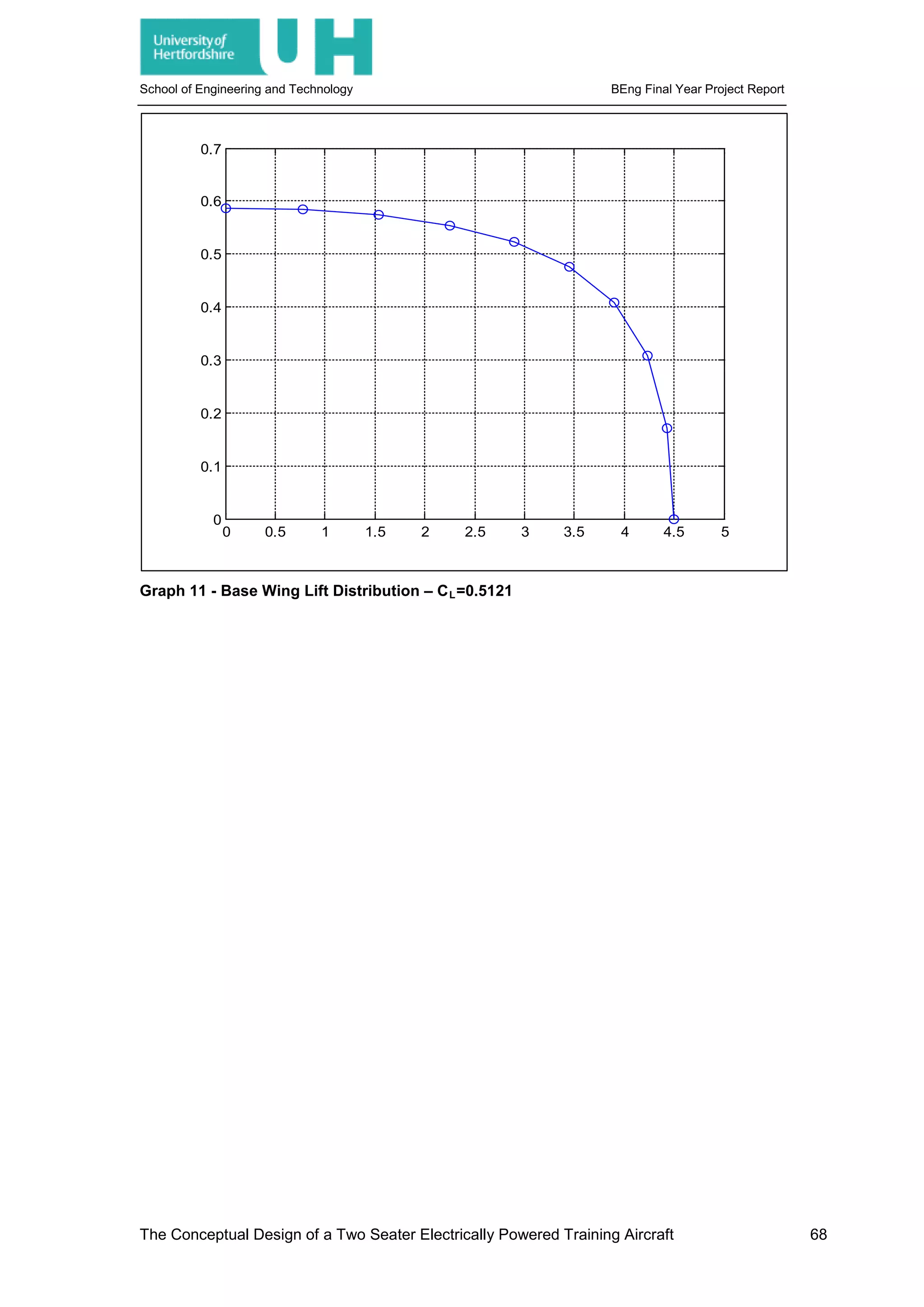
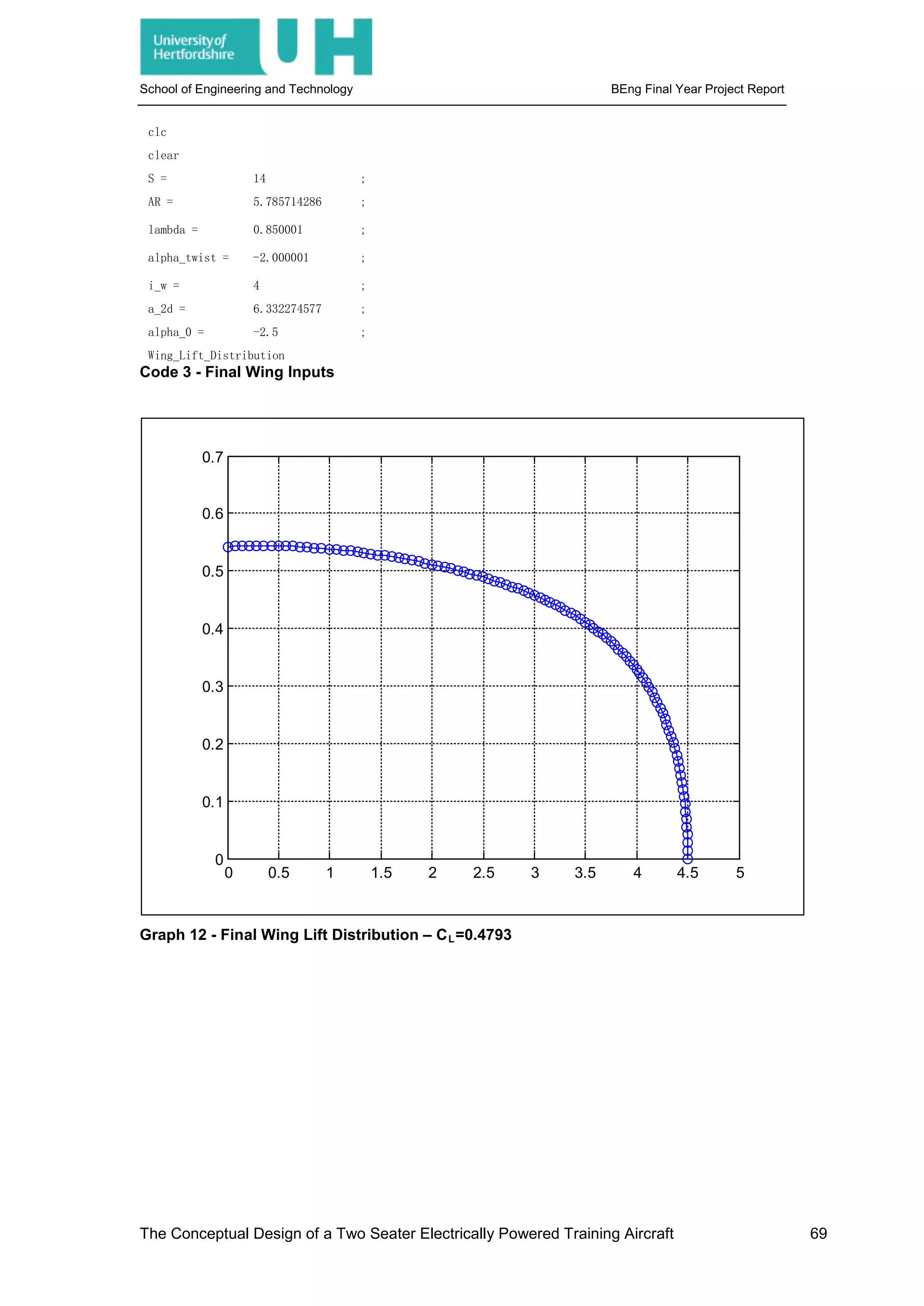
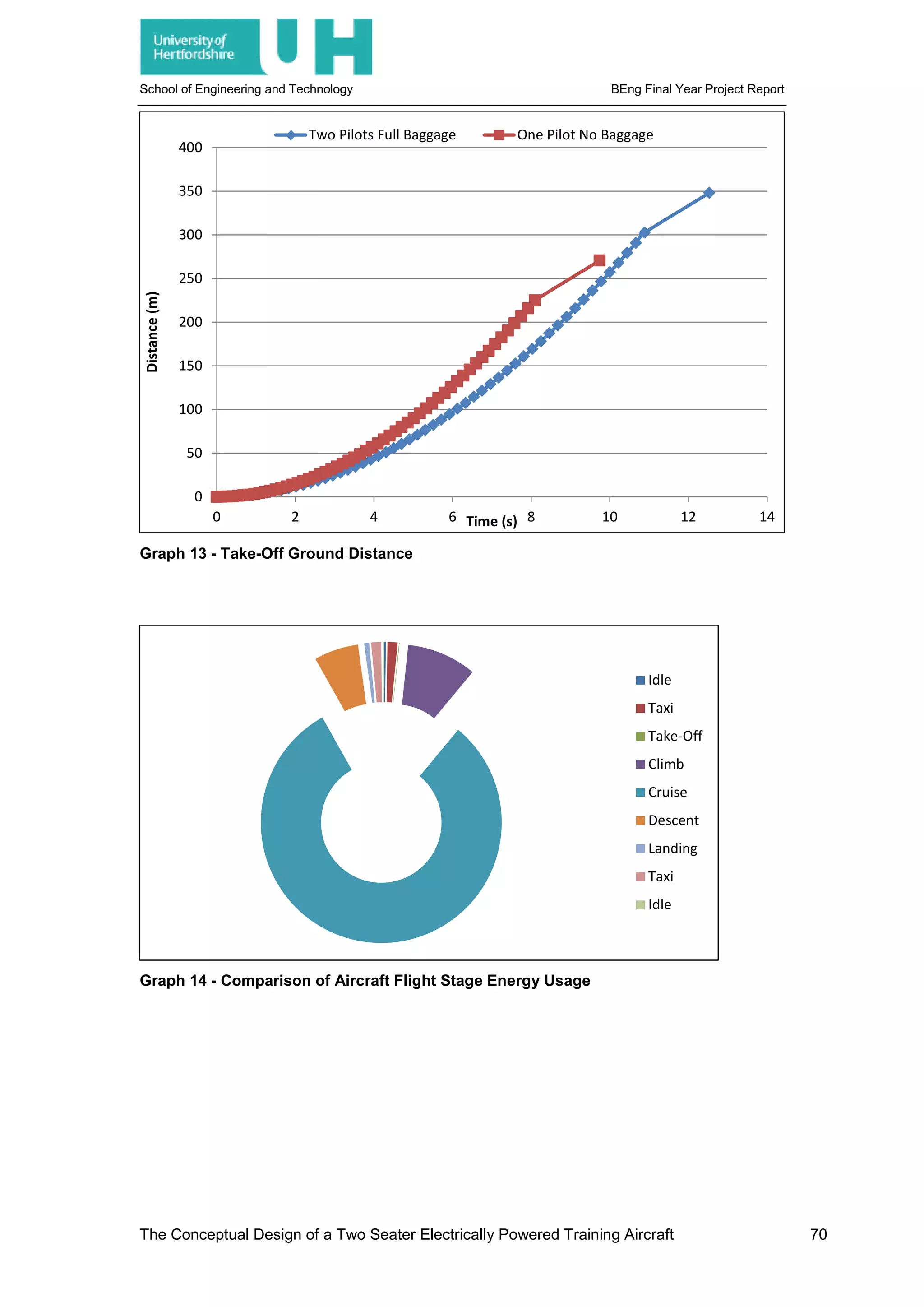
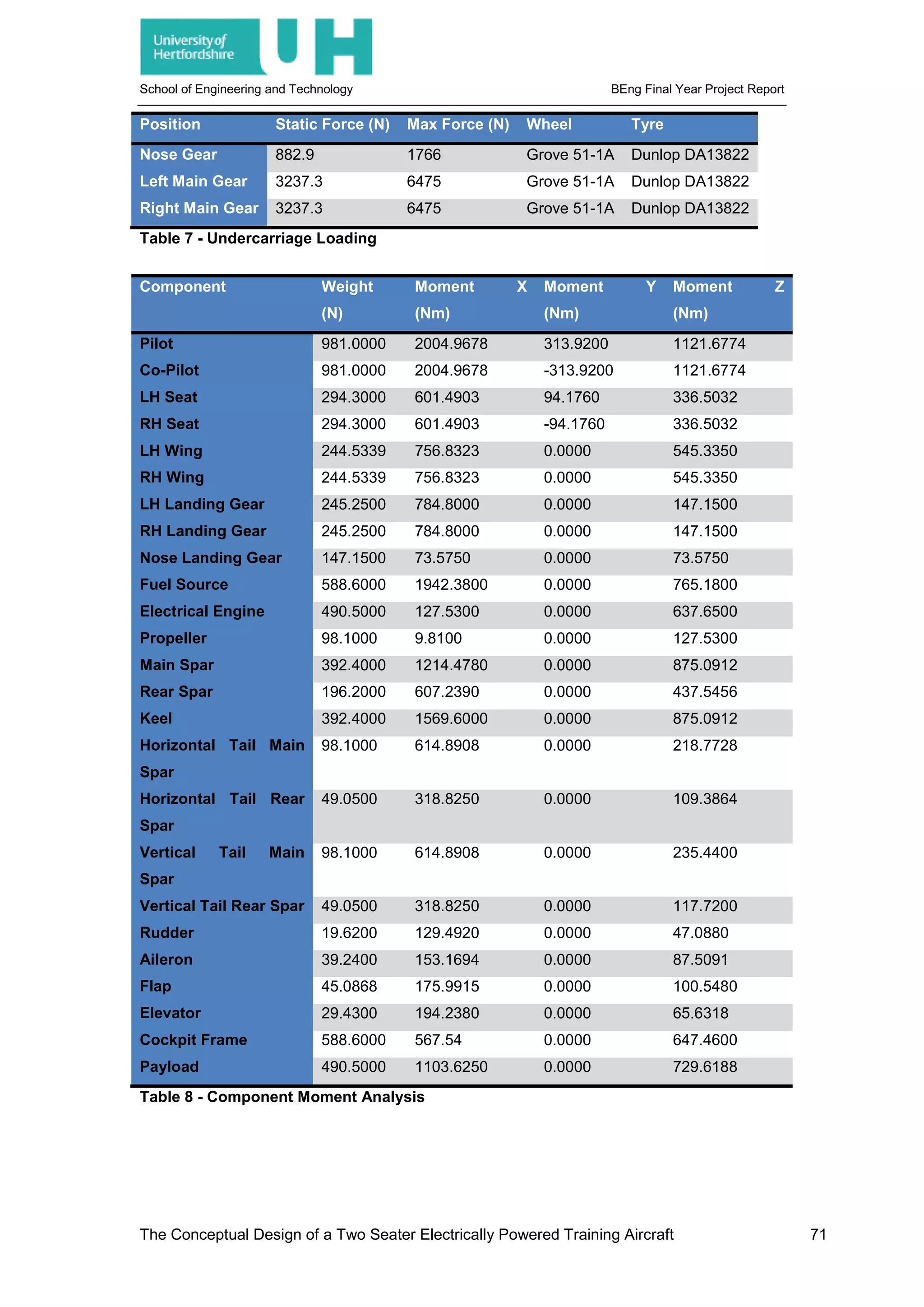
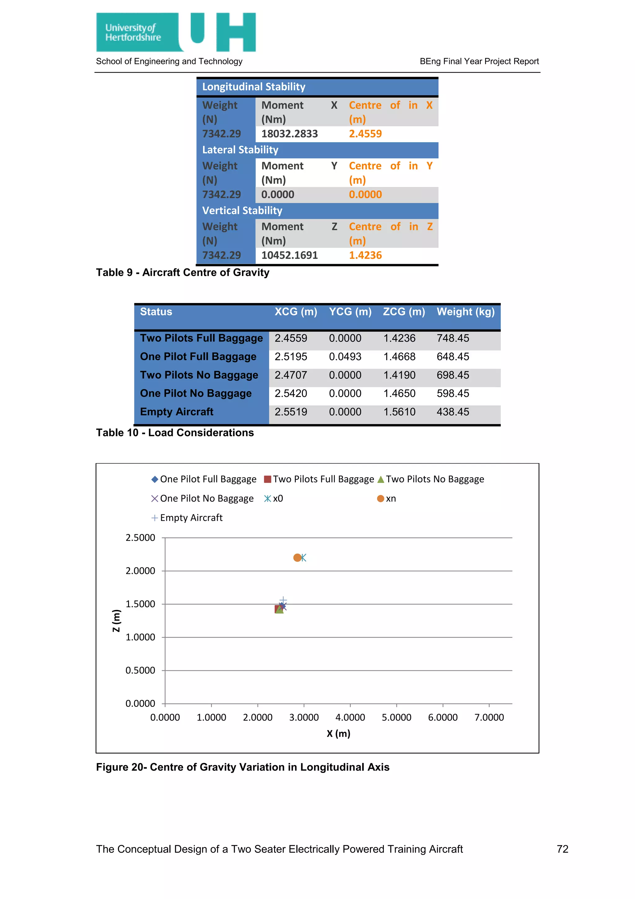
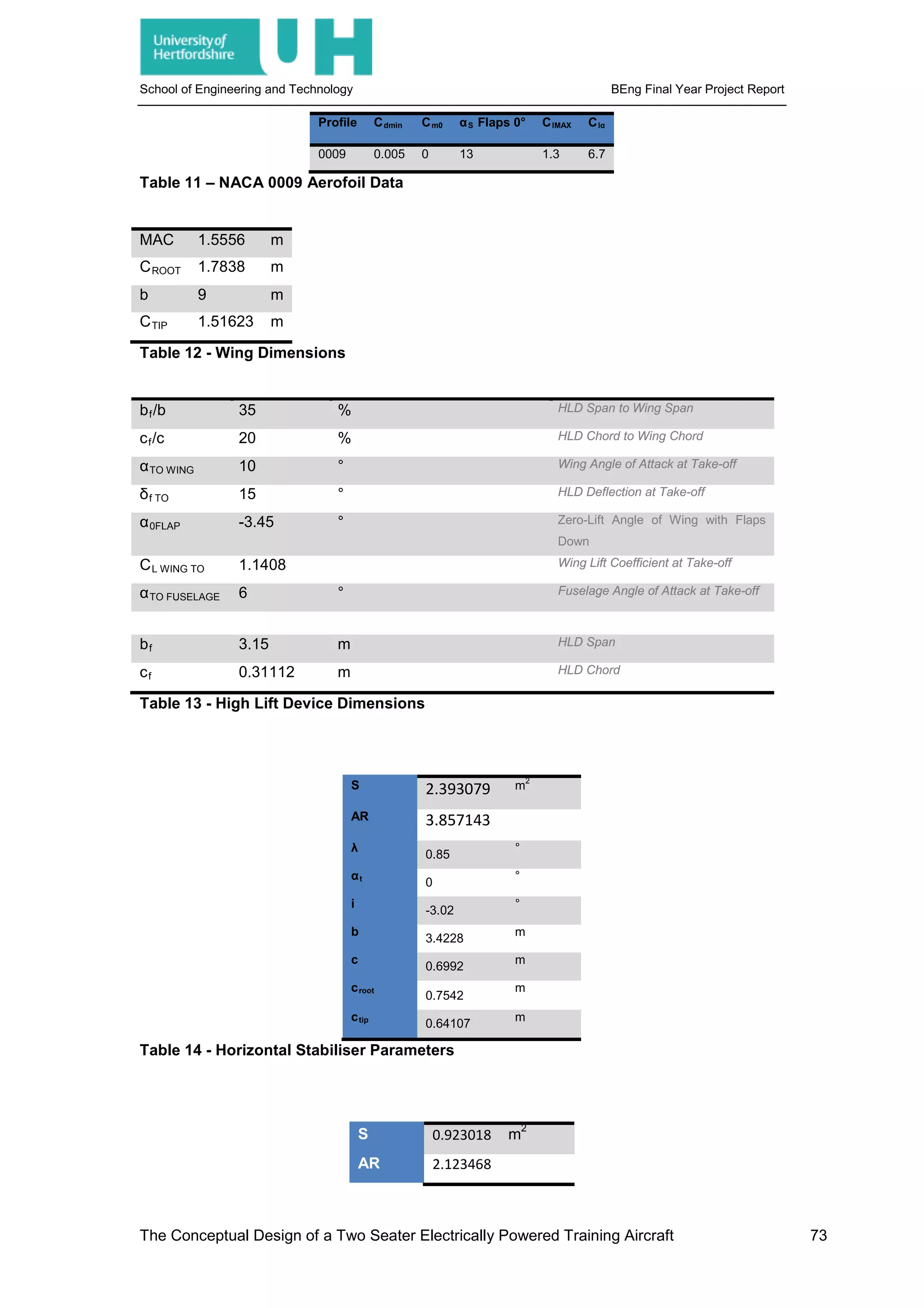
![School of Engineering and Technology BEng Final Year Project Report
Λ 70 °
b 1.4 m
c 0.659299 m
Table 15- Vertical Stabiliser Parameters
Phugoid Mode
Level 1 ζ > 0.04
Level 2 ζ > 0
Level 3 T2 > 55
Short Period Mode
Category A and C Category B
ζ ζ ζ ζ
Level min max min max
1 0.35 1.3 0.3 2
2 0.25 2 0.2 2
3 0.15 --- 0.15 ---
Table 16 - Longitudinal Flying Characteristics - [28]
Spiral Mode
Class Category Level 1 Level 2 Level 3
I, IV A 12s 12s 4s
B, C 20s 12s 4s
II, III All 20s 12s 4s
Roll Convergence
Class Category Level 1 Level 2 Level 3
I,IV A 1.0s 1.4s 10s
II,III A 1.4s 3.0s 10s
All B 1.4s 3.0s 10s
I,IV C 1.0s 1.4s 10s
II,III C 1.4s 3.0s 10s
Dutch Roll Mode
Level Category Class Min 𝜁𝜁 Min 𝜁𝜁𝜔𝜔𝑛𝑛 Min 𝜔𝜔𝑛𝑛
1 A I,IV 0.19 0.35 1.0
1 A II,III 0.19 0.35 0.4
1 B All 0.08 0.15 0.4
1 C I,II-C,IV 0.08 0.15 1.0
1 C II-L,III 0.08 0.15 0.4
2 All All 0.02 0.05 0.4
3 All All 0.02 --- 0.4
Table 17 - Lateral Flying Characteristics - [28]
The Conceptual Design of a Two Seater Electrically Powered Training Aircraft 74](https://image.slidesharecdn.com/0442df0a-d8dc-4f9c-9b24-9e5eae2820ed-160330152913/75/JOHNSON_BENJAMIN_11379847_Report-90-2048.jpg)