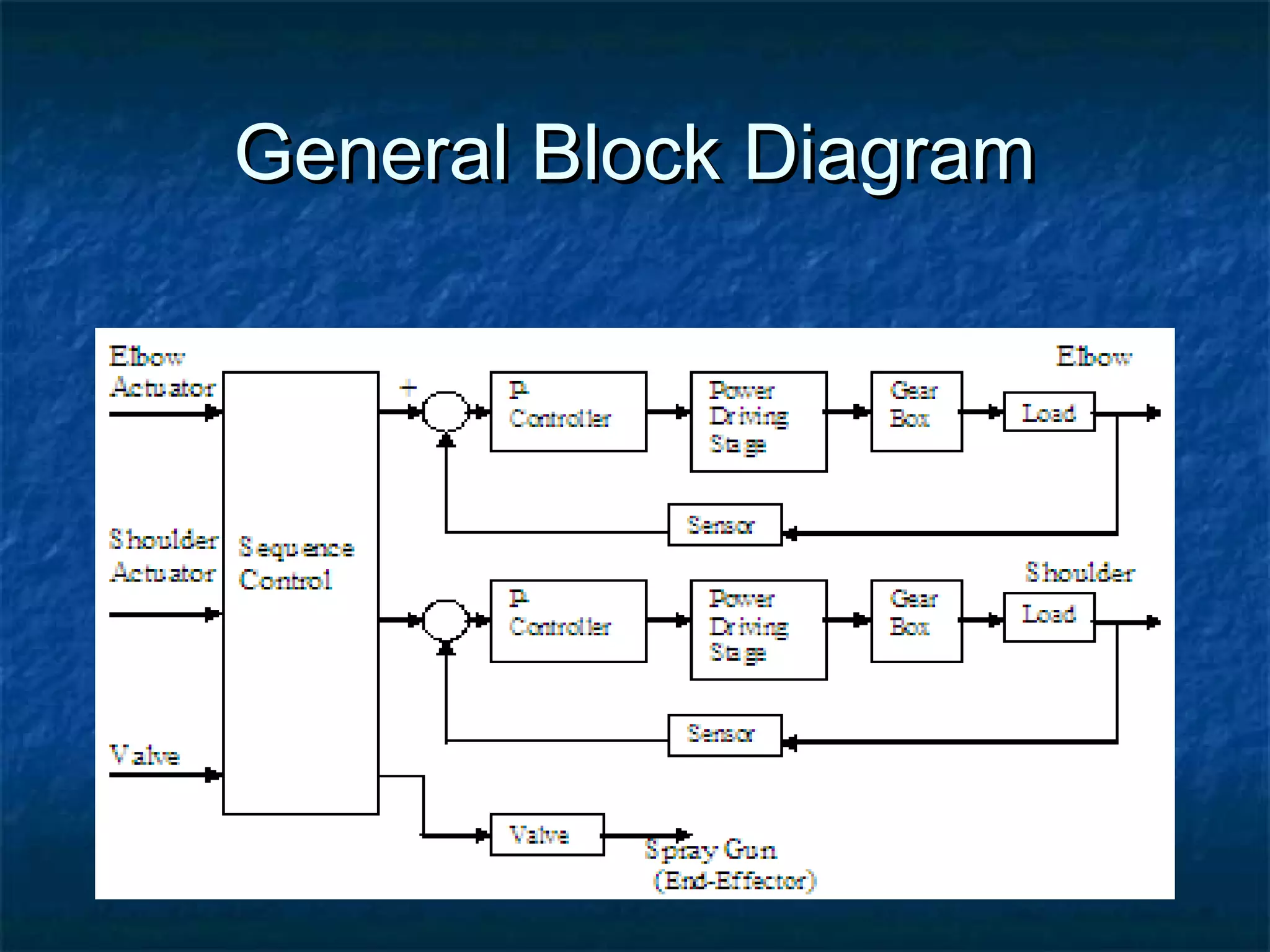
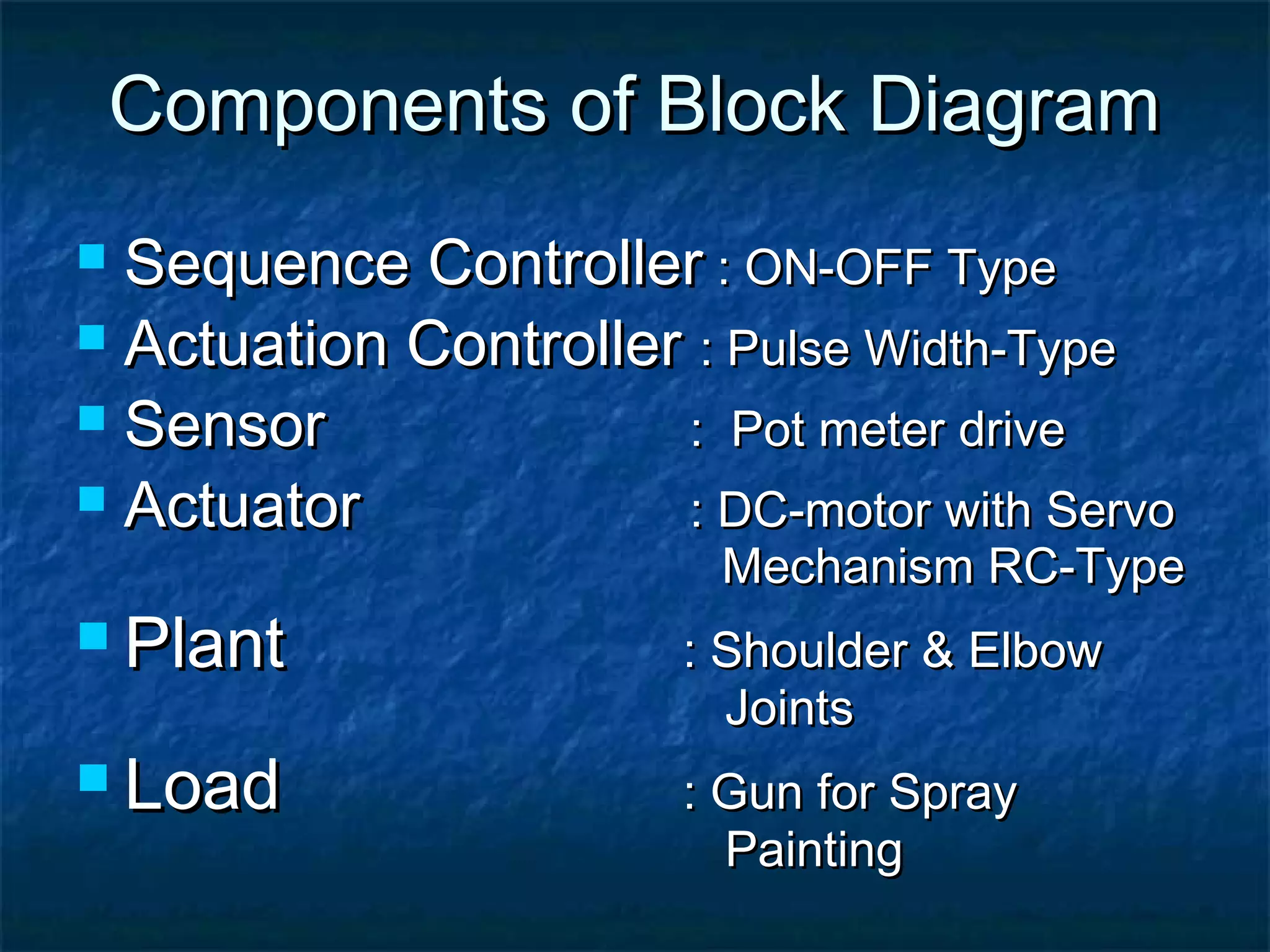
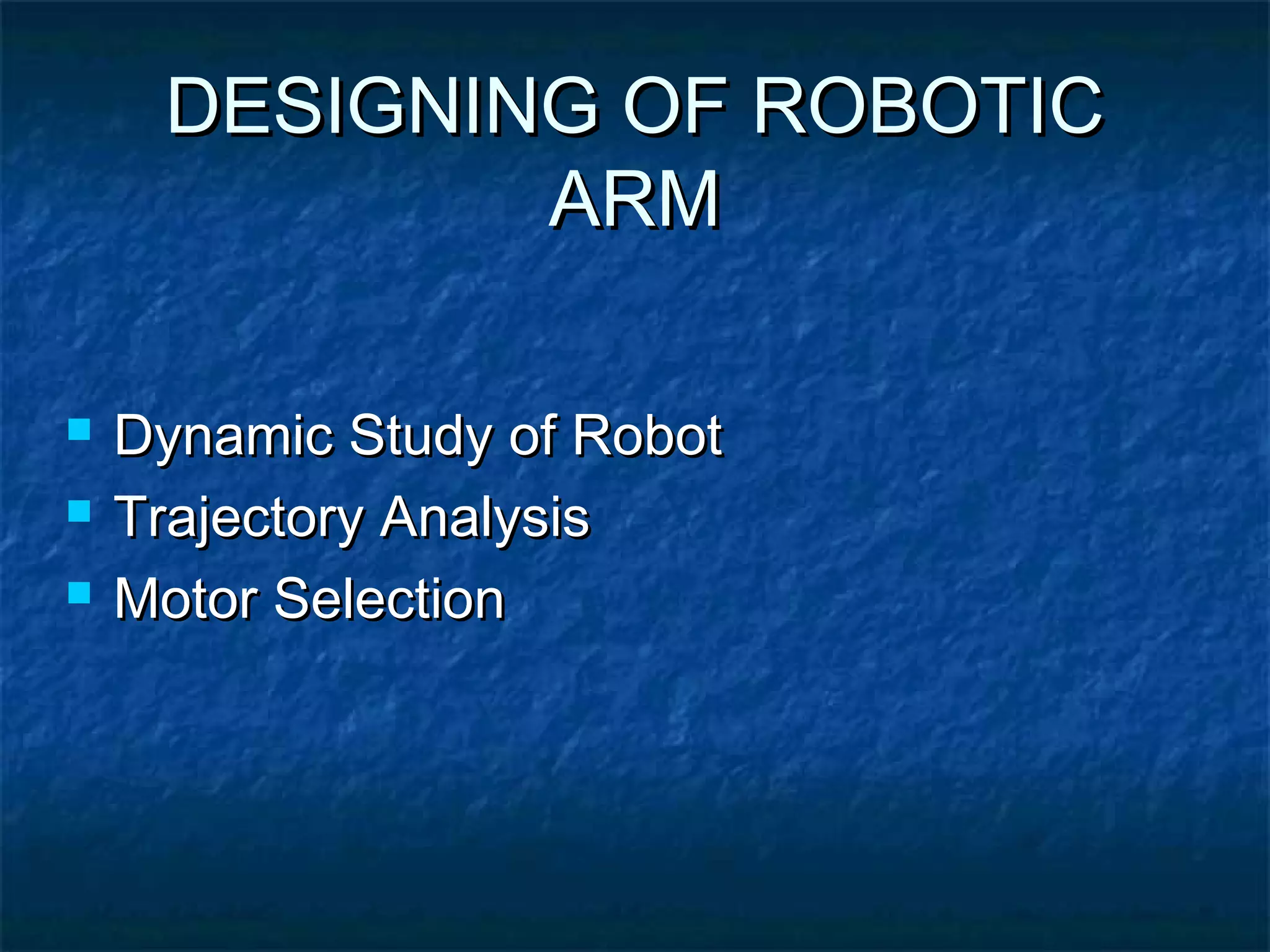
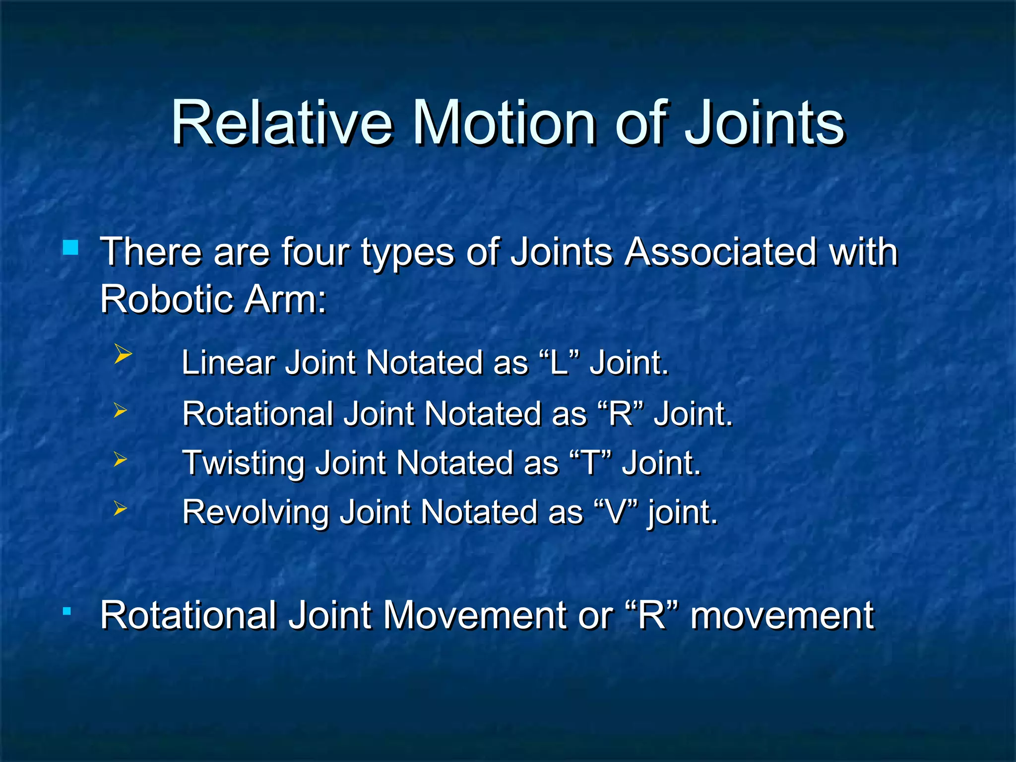
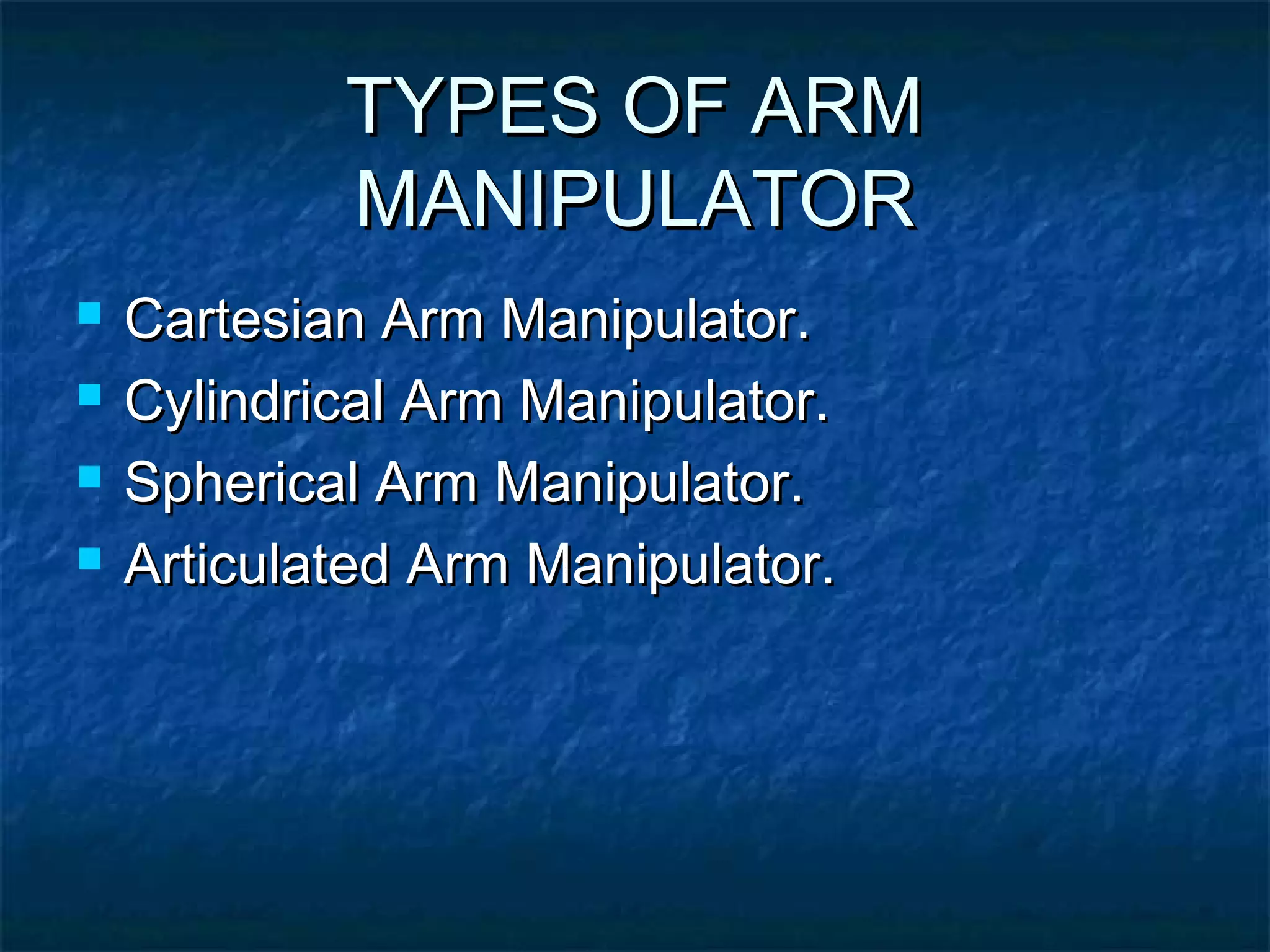
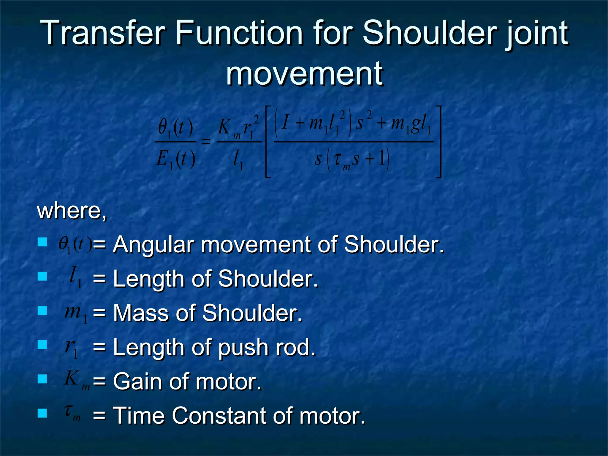
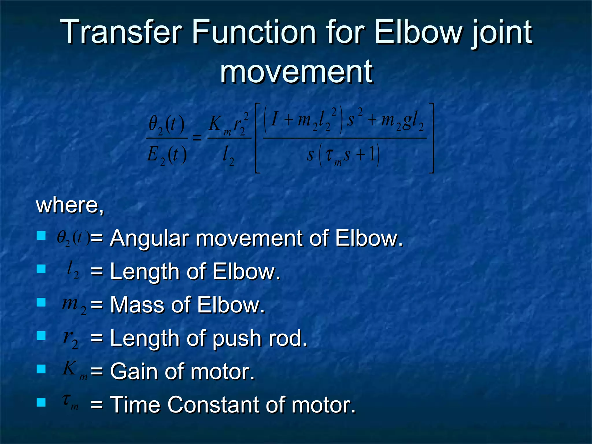
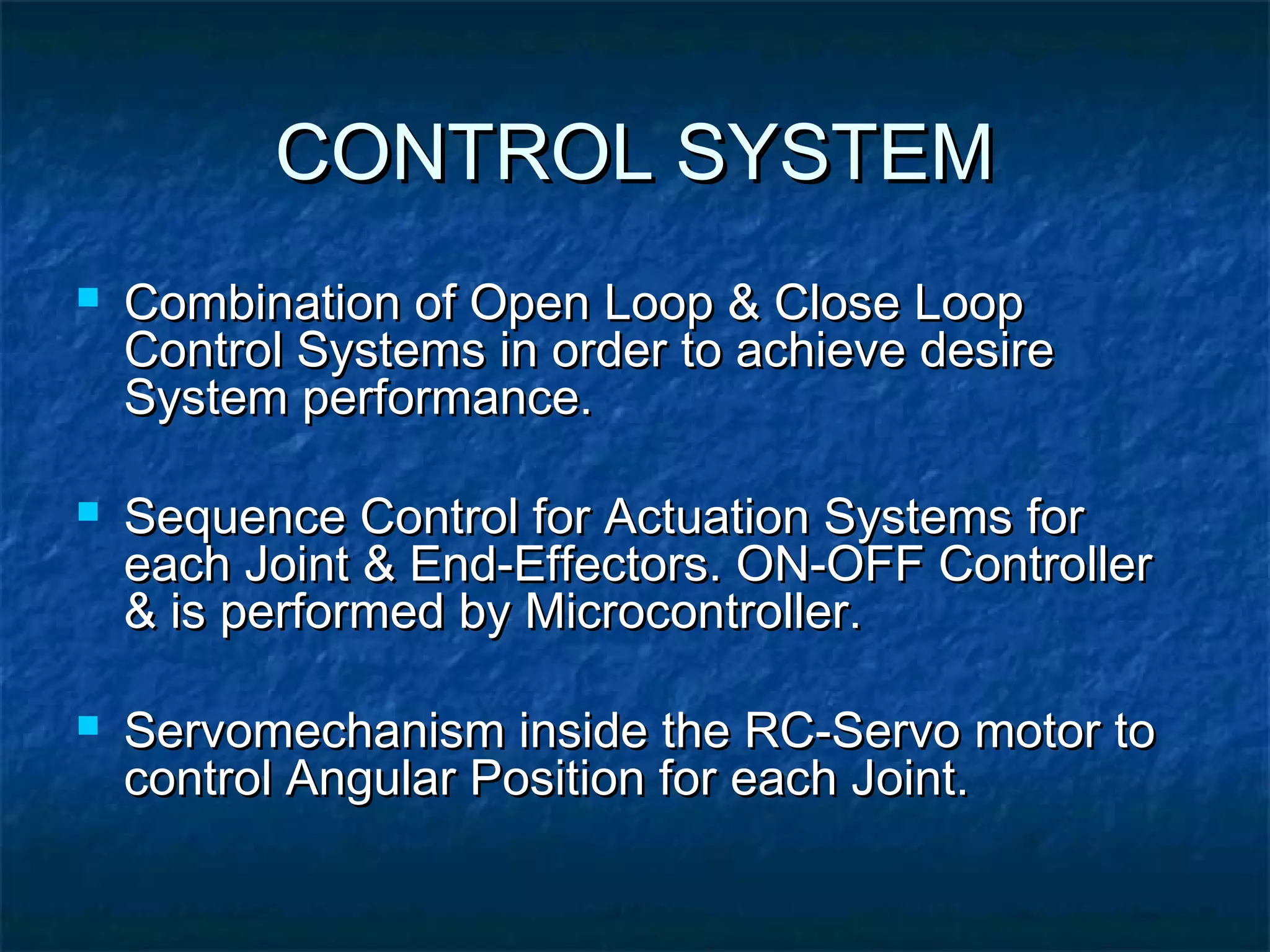
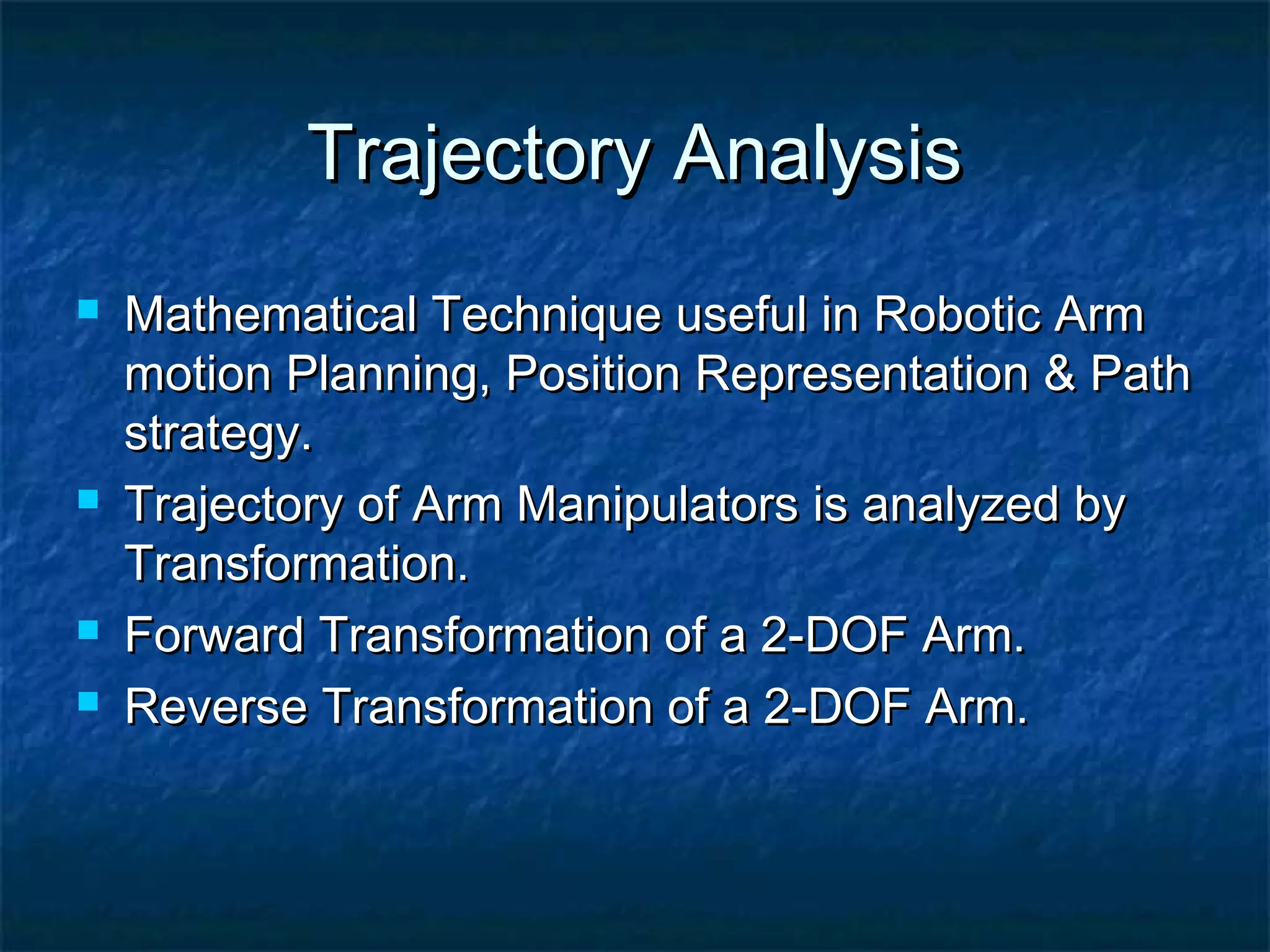
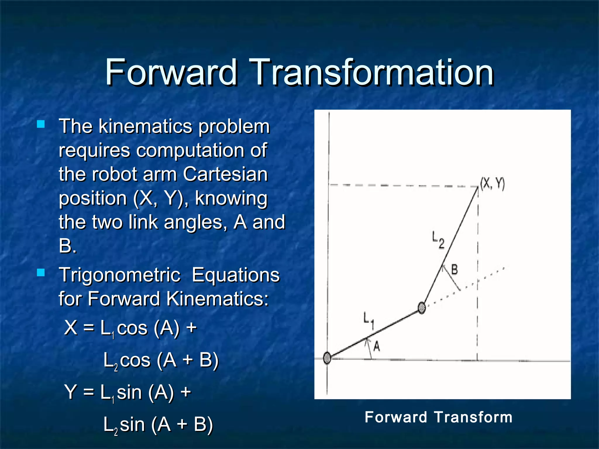
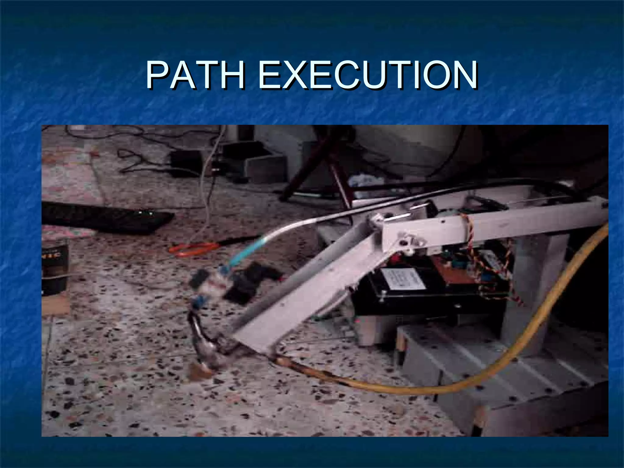
This document describes the design of an automatic spray painter using a 2 degree-of-freedom articulated robotic arm. The objective is to design a robotic arm that can paint any character from A to Z or any number from 0 to 9. The system uses programmable automation and consists of actuators, sensors, a microcontroller and other electronic components. The articulated robotic arm has revolute joints at the shoulder and elbow. DC servo motors with gearboxes are used as actuators to provide the required torque and angular motion. The trajectory and kinematics of the 2-DOF arm are analyzed using forward and inverse transformations. An end effector spray gun is used to apply paint in the desired patterns.
Jim Stertz: Automation and Robotic Arm: Maximizing Throughput and Capacity360mnbsu
A medical device contract manufacturer developed and implemented an automated system and a robotic arm to tend three inspection Coordinate Measuring Machines. This presentation will be a case study of their throughput, uptime, and capacity expansions using automation.
From the 2014 Taking Shape Summit: The Internet of Things & the Future of Manufacturing.
Servo Based 5 Axis Robotic Arm Project ReportRobo India
Robo India presents a project report on servo motor based 5 axis robotic arm.
This project is operated through PC software that is made in Visual Basic. AVR family's Atmel Atmega 8 is used in controller board, it runs on Arduino IDE platform.
Detailed mechnical drawings of all of the parts are also given.
We welcome all of your views and queries.
Thanks & Regards
Team Robo India
www.roboindia.com
info@roboindia.com
This is the basic tutorial for understanding robotic arm with open source project JavaRobot controlling robotic arm. JavaRobot is an open source Matlab API for controlling YASKAWA MH12.
A pick and place robot with a end effector to grip and place objects in your desired location,controlled by RF communication. Pick and place robot has many advantages and it uses in military, medical and defense applications.
Robotic Arm using flex sensor and servo motorjovin Richard
A robotic arm is a type of mechanical arm, usually programmable, with similar functions to a human arm; the arm may be the sum total of the mechanism or may be part of a more complex robot. we have used FLEX SENSOR for the inuput and SERVO MOTOR as output for the movement. Motor Driver L293D is used to increase the power. atmega8 is used here.
Poster for our presentation on our Autonomous Robotic Arm that detects objects with an overhead camera, uses motion planning and reverse kinematics to retrieve objects, and places the objects in a bin. This project was done as part of the EECS 498 Autonomous Robotics Lab at the University of Michigan.
Plc based Robotic Arm and Automated Different Size Bottle Filling SystemRehan Fazal
Well this was going to be our final year project but it got rejected after being accepted by panel members in zeroth review by our HOD mam.
If u want to do this project or use the idea of this project seriously after getting all your formalities done, you can contact me. I will help you in getting all your IEEE papers and relevant papers to this project.
The reason behind sharing this is that I spend my whole one semester for studying theory part of it, and i was unable to do this but i really want someone to do this project.
In our contemporary world of science & technology, most of us are
going for automation. Robotics covers a large area in the automated
world and robotic arm has become popular in the world of robotics.
Robotic arm can do such operations which are difficult & dangerous
for human (e.g. removing mines, mining operations and so on). Even
robotic arm is doing critical surgery of brain. In our project of robotic
arm, our main intention was to control it by the microcontroller. By
doing this we miniaturized the control section of the robotic arm.
The Graphiti framework is a new approach to create highly sophisticated visual editors on top of the GEF framework. Graphiti can easily be integrated with EMF as the domain modeling framework. The creation of visual editors is done in Java, programming against the Graphiti framework API. It is fairly simple, but yet repetitive, which makes it a candidate to be supported by the means of model-driven development.
Spray aims to provide Domain Specific Languages (DSL) (implemented with Xtext) to describe Visual DSL Editors against the Graphiti runtime, and provide code generation (implemented with Xtend) to create the boilerplate code for realizing the implementation against the Graphiti framework. Potentially the Spray DSL can be used to generate code for other graphical editor frameworks as well, although it is not the primary focus of the project now.
The generated code is structured in such a way that one can always extend/overwrite the generated code with handwritten Java to add advanced Graphiti features that are not supported directly by the Spray DSL. Therefore Spray makes use of the "Generation Gap Pattern".
With the help of the tools created with Spray, Graphiti based diagram editors can be created much faster and reliable than doing it purely by hand.
Institute of infrastructure technology research and management (IITRAM) Ahmedabad. This is the project report given to us in the control sytem lab. This is basically a Servo postion control. Here we are using PID controller.
Industrial Robots, Robot Anatomy,Joints, Robot Configurations, Robot Actuators/ Drive systems,Robot programming, Teach pendant Programming, Lead through Programming, Robot control systems,Applications,Advatages
Design, Implementation and Control of a Humanoid Robot for Obstacle Avoidance...IOSR Journals
Abstract: In this paper, the design, implementation and control of a humanoid robot, which enables humanlike
walk and a path planning of humanoid robot for obstacle avoidance by using infrared sensors (IRs) is
proposed. As the focus is to obtain human-like walk, the robot is designed to resemble human proportions.
Based on the obtained information from IR sensors, a software flow proposed to decide the behaviour of robot
so that the robot avoids obstacles and goes to the destination. Furthermore the hardware and software
necessary to obtain a fully autonomous system is developed and implemented. Human-like walk was not
obtained on the real system, due to system limitations. If a new interface to the DC-motors in the servos was
developed, and a faster on-board computer was chosen, human-like walk should be possible.
Keywords- Humanoid robot, Autonomous mobile robot, Obstacle avoidance, IR sensors, servo motors, 8051
Micro controller.
Design, Implementation and Control of a Humanoid Robot for Obstacle Avoidance...IOSR Journals
In this paper, the design, implementation and control of a humanoid robot, which enables humanlike
walk and a path planning of humanoid robot for obstacle avoidance by using infrared sensors (IRs) is
proposed. As the focus is to obtain human-like walk, the robot is designed to resemble human proportions.
Based on the obtained information from IR sensors, a software flow proposed to decide the behaviour of robot
so that the robot avoids obstacles and goes to the destination. Furthermore the hardware and software
necessary to obtain a fully autonomous system is developed and implemented. Human-like walk was not
obtained on the real system, due to system limitations. If a new interface to the DC-motors in the servos was
developed, and a faster on-board computer was chosen, human-like walk should be possible.
Robotics is an interdisciplinary branch of computer science and engineering.[1] Robotics involves design, construction, operation, and use of robots. The goal of robotics is to design machines that can help and assist humans. Robotics integrates fields of mechanical engineering, electrical engineering, information engineering, mechatronics, electronics, bioengineering, computer engineering, control engineering, software engineering, mathematics, etc.
Robotics develops machines that can substitute for humans and replicate human actions. Robots can be used in many situations for many purposes, but today many are used in dangerous environments (including inspection of radioactive materials, bomb detection and deactivation), manufacturing processes, or where humans cannot survive (e.g. in space, underwater, in high heat, and clean up and containment of hazardous materials and radiation). Robots can take any form, but some are made to resemble humans in appearance. This is claimed to help in the acceptance of robots in certain replicative behaviors which are usually performed by people. Such robots attempt to replicate walking, lifting, speech, cognition, or any other human activity. Many of today's robots are inspired by nature, contributing to the field of bio-inspired robotics.
Certain robots require user input to operate while other robots function autonomously. The concept of creating robots that can operate autonomously dates back to classical times, but research into the functionality and potential uses of robots did not grow substantially until the 20th century. Throughout history, it has been frequently assumed by various scholars, inventors, engineers, and technicians that robots will one day be able to mimic human behavior and manage tasks in a human-like fashion. Today, robotics is a rapidly growing field, as technological advances continue; researching, designing, and building new robots serve various practical purposes, whether domestically, commercially, or militarily. Many robots are built to do jobs that are hazardous to people, such as defusing bombs, finding survivors in unstable ruins, and exploring mines and shipwrecks. Robotics is also used in STEM (science, technology, engineering, and mathematics) as a teaching aid.[2]
3. GROUP MEMBERSGROUP MEMBERS
Shahzad Ali BajwaShahzad Ali Bajwa (1533)(1533)
M. Ayaz ButtM. Ayaz Butt (1520)(1520)
M. Zeeshan TajM. Zeeshan Taj (1528)(1528)
S. M. UmerS. M. Umer (1537)(1537)
4. OBJECTIVEOBJECTIVE
To design Automatic Spray Painter by 2-To design Automatic Spray Painter by 2-
DOF Robotic Arm that can paint :DOF Robotic Arm that can paint :
Any Character from A to Z.Any Character from A to Z.
Any Number from 0 to 9.Any Number from 0 to 9.
5. MOTIVATION FOR THISMOTIVATION FOR THIS
PROJECTPROJECT
A step in the field of Automation andA step in the field of Automation and
Robotics.Robotics.
Provides us with a good experience forProvides us with a good experience for
designing an Embedded System.designing an Embedded System.
Could enhance our Programming andCould enhance our Programming and
Mechatronic Skills.Mechatronic Skills.
A system already being used in manyA system already being used in many
Automobile Industries today.Automobile Industries today.
6. AUTOMATION & ROBOTICSAUTOMATION & ROBOTICS
Automation as Technology is concerned withAutomation as Technology is concerned with
the use of Mechanical, Electronics andthe use of Mechanical, Electronics and
Computer based System in Operation &Computer based System in Operation &
Control of Production.Control of Production.
Industrial Robot is a Programmable MachineIndustrial Robot is a Programmable Machine
Which Possesses Human like CharacteristicsWhich Possesses Human like Characteristics
to perform Automation.to perform Automation.
7. TYPE OF AUTOMATIONTYPE OF AUTOMATION
SELECTEDSELECTED
Fixed AutomationFixed Automation
Flexible AutomationFlexible Automation
Programmable AutomationProgrammable Automation
Programmable Automation was Selected.Programmable Automation was Selected.
9. Components of Block DiagramComponents of Block Diagram
Sequence ControllerSequence Controller : ON-OFF Type: ON-OFF Type
Actuation ControllerActuation Controller : Pulse Width-Type: Pulse Width-Type
SensorSensor : Pot meter drive: Pot meter drive
ActuatorActuator : DC-motor with Servo: DC-motor with Servo
Mechanism RC-TypeMechanism RC-Type
PlantPlant : Shoulder & Elbow: Shoulder & Elbow
JointsJoints
LoadLoad : Gun for Spray: Gun for Spray
PaintingPainting
10. MAIN TOPICSMAIN TOPICS
Designing of Robotic Arm.Designing of Robotic Arm.
Mechanical Section.Mechanical Section.
Software & Logic Design.Software & Logic Design.
Electronics.Electronics.
11. DESIGNING OF ROBOTICDESIGNING OF ROBOTIC
ARMARM
Dynamic Study of RobotDynamic Study of Robot
Trajectory AnalysisTrajectory Analysis
Motor SelectionMotor Selection
13. Frame of ReferenceFrame of Reference
Coordinate System that may have otherCoordinate System that may have other
Points or Paths defined Relative to it.Points or Paths defined Relative to it.
Types:Types:
Absolute Frame of Reference.Absolute Frame of Reference.
Relative Frame of Reference.Relative Frame of Reference.
Absolute Frame of Reference wasAbsolute Frame of Reference was
Selected.Selected.
14. Degree of Freedom (DOF)Degree of Freedom (DOF)
The Individual Joint Motion AssociatedThe Individual Joint Motion Associated
with Arm & Wrist is termed as Degree ofwith Arm & Wrist is termed as Degree of
Freedom (DOF).Freedom (DOF).
3 DOF associate with Arm Joints are:3 DOF associate with Arm Joints are:
Vertical Traverse or Pitch movement.Vertical Traverse or Pitch movement.
Radial Traverse or Too & Fro movement.Radial Traverse or Too & Fro movement.
Rotational Traverse or Yaw movement.Rotational Traverse or Yaw movement.
15. DOF Associated with Our ArmDOF Associated with Our Arm
manipulatormanipulator
Vertical Traverse or Pitch movement ofVertical Traverse or Pitch movement of
Elbow.Elbow.
Rotational Traverse or Yaw movement ofRotational Traverse or Yaw movement of
Shoulder.Shoulder.
16. Relative Motion of JointsRelative Motion of Joints
There are four types of Joints Associated withThere are four types of Joints Associated with
Robotic Arm:Robotic Arm:
Linear Joint Notated as “L” Joint.Linear Joint Notated as “L” Joint.
Rotational Joint Notated as “R” Joint.Rotational Joint Notated as “R” Joint.
Twisting Joint Notated as “T” Joint.Twisting Joint Notated as “T” Joint.
Revolving Joint Notated as “V” joint.Revolving Joint Notated as “V” joint.
Rotational Joint Movement or “R” movementRotational Joint Movement or “R” movement
17. TYPES OF ARMTYPES OF ARM
MANIPULATORMANIPULATOR
Cartesian Arm Manipulator.Cartesian Arm Manipulator.
Cylindrical Arm Manipulator.Cylindrical Arm Manipulator.
Spherical Arm Manipulator.Spherical Arm Manipulator.
Articulated Arm Manipulator.Articulated Arm Manipulator.
19. ADVANTAGESADVANTAGES
Maximum flexibilityMaximum flexibility
Covers a large work space relative toCovers a large work space relative to
volume of robotsvolume of robots
Revolute joints are easy to sealRevolute joints are easy to seal
Suits electric motorsSuits electric motors
Can reach over and under objectsCan reach over and under objects
20. Transfer Function for Shoulder jointTransfer Function for Shoulder joint
movementmovement
where,where,
= Angular movement of Shoulder.= Angular movement of Shoulder.
= Length of Shoulder.= Length of Shoulder.
= Mass of Shoulder.= Mass of Shoulder.
= Length of push rod.= Length of push rod.
= Gain of motor.= Gain of motor.
= Time Constant of motor.= Time Constant of motor.
1( )tθ
1l
( )
( )
2 22
1 1 1 11 1
1 1
( )
( ) 1
m
m
I m l s m glt K r
E t l s s
θ
τ
+ +
=
+
1m
1r
mK
mτ
21. Transfer Function for Elbow jointTransfer Function for Elbow joint
movementmovement
where,where,
= Angular movement of Elbow.= Angular movement of Elbow.
= Length of Elbow.= Length of Elbow.
= Mass of Elbow.= Mass of Elbow.
= Length of push rod.= Length of push rod.
= Gain of motor.= Gain of motor.
= Time Constant of motor.= Time Constant of motor.
2 ( )tθ
2l
( )
( )
2 22
2 2 2 22 2
2 2
( )
( ) 1
m
m
I m l s m glt K r
E t l s s
θ
τ
+ +
=
+
2m
2r
mK
mτ
22. CONTROL SYSTEMCONTROL SYSTEM
Combination of Open Loop & Close LoopCombination of Open Loop & Close Loop
Control Systems in order to achieve desireControl Systems in order to achieve desire
System performance.System performance.
Sequence Control for Actuation Systems forSequence Control for Actuation Systems for
each Joint & End-Effectors. ON-OFF Controllereach Joint & End-Effectors. ON-OFF Controller
& is performed by Microcontroller.& is performed by Microcontroller.
Servomechanism inside the RC-Servo motor toServomechanism inside the RC-Servo motor to
control Angular Position for each Joint.control Angular Position for each Joint.
24. Trajectory AnalysisTrajectory Analysis
Mathematical Technique useful in Robotic ArmMathematical Technique useful in Robotic Arm
motion Planning, Position Representation & Pathmotion Planning, Position Representation & Path
strategy.strategy.
Trajectory of Arm Manipulators is analyzed byTrajectory of Arm Manipulators is analyzed by
Transformation.Transformation.
Forward Transformation of a 2-DOF Arm.Forward Transformation of a 2-DOF Arm.
Reverse Transformation of a 2-DOF Arm.Reverse Transformation of a 2-DOF Arm.
25. Forward TransformationForward Transformation
The kinematics problemThe kinematics problem
requires computation ofrequires computation of
the robot arm Cartesianthe robot arm Cartesian
position (X, Y), knowingposition (X, Y), knowing
the two link angles, A andthe two link angles, A and
B.B.
Trigonometric EquationsTrigonometric Equations
for Forward Kinematics:for Forward Kinematics:
X = LX = L11 cos (A) +cos (A) +
LL22 cos (A + B)cos (A + B)
Y = LY = L11 sin (A) +sin (A) +
LL22 sin (A + B)sin (A + B) Forward Transform
26. Inverse TransformationInverse Transformation
The kinematics problemThe kinematics problem
is seen to be fairly easyis seen to be fairly easy
to solve. The inverseto solve. The inverse
problem, that of finding Aproblem, that of finding A
and B.and B.
Trigonometric EquationsTrigonometric Equations
for Inverse Kinematics:for Inverse Kinematics:
Inverse Transform
28. Actuation SystemActuation System
Type of Actuators used in RoboticType of Actuators used in Robotic
Joint:Joint:
- Pneumatic & Hydraulic Actuators.- Pneumatic & Hydraulic Actuators.
- Electric Motors.- Electric Motors.
29. Type of Actuator Choose forType of Actuator Choose for
Robotic movementRobotic movement
Electric Motors were chosen for RoboticElectric Motors were chosen for Robotic
movement.movement.
Easy to modeled.Easy to modeled.
Types of Electric Motors:Types of Electric Motors:
AC-Motors.AC-Motors.
DC-Motors.DC-Motors.
30. Type of Electric Motor Choose forType of Electric Motor Choose for
Robotic movementRobotic movement
DC-Motor is Chosen for Robotic Movement.DC-Motor is Chosen for Robotic Movement.
Types of DC-Motors:Types of DC-Motors:
Stepper Motor.Stepper Motor.
DC-Motor ( Geared & Un-Geared).DC-Motor ( Geared & Un-Geared).
Servo Motor (DC-Motor with Feedback).Servo Motor (DC-Motor with Feedback).
RC-Servo Motor (DC-Motor with Servo-RC-Servo Motor (DC-Motor with Servo-
Mechanism).Mechanism).
31. Why RC-Servo Motor is Chosen forWhy RC-Servo Motor is Chosen for
Actuation Purpose?Actuation Purpose?
Built-in Designed Servo Mechanism.Built-in Designed Servo Mechanism.
Easy to Couple with Joints.Easy to Couple with Joints.
Suitable & preferable Actuator in all to StudySuitable & preferable Actuator in all to Study
Dynamics of any type of joint .Dynamics of any type of joint .
Need to Estimate Torque twice the Torque ofNeed to Estimate Torque twice the Torque of
Joint.Joint.
32. ANGULAR MOTIONANGULAR MOTION
Depends on PulseDepends on Pulse
Width.Width.
Motion BetweenMotion Between
1msec to 2msec1msec to 2msec
Pulse WidthPulse Width
corresponds to 0degcorresponds to 0deg
to 180deg.to 180deg.
9deg per 0.05msec of9deg per 0.05msec of
Pulse Width.Pulse Width.
33. BLOCK DIAGRAM FOR RC-BLOCK DIAGRAM FOR RC-
SERVO MECHANISMSERVO MECHANISM
34. Components of Block DiagramComponents of Block Diagram
Feedback Potentiometer.Feedback Potentiometer.
Digital Comparator.Digital Comparator.
Pulse width Controller.Pulse width Controller.
MOSFET based H-Bridge.MOSFET based H-Bridge.
Gear Box.Gear Box.
Servo Arm.Servo Arm.
35. Gear BoxGear Box
Gear Box in Motor Provide Motor High Torque &Gear Box in Motor Provide Motor High Torque &
Longer Life.Longer Life.
Types of Gear Box in RC-Servo Motor:Types of Gear Box in RC-Servo Motor:
Nylon Gears.Nylon Gears.
Carbonize Gears.Carbonize Gears.
Metal Gears.Metal Gears.
36. Type of Gear Box in SelectedType of Gear Box in Selected
RC-Servos.RC-Servos.
The Servo Motor of Shoulder Joint hasThe Servo Motor of Shoulder Joint has
Carbonize Gear Box.Carbonize Gear Box.
The Servo Motor of Elbow Joint has MetalThe Servo Motor of Elbow Joint has Metal
Gear Box.Gear Box.
37. Data for RC-Servo Used inData for RC-Servo Used in
Shoulder JointShoulder Joint
RC-Servo used in Shoulder Joint is 635-HB ofRC-Servo used in Shoulder Joint is 635-HB of
Hi-Tech.Hi-Tech.
Control System: Pulse Width Control.Control System: Pulse Width Control.
Bearing Type: Ball Bearing.Bearing Type: Ball Bearing.
Weight: 52.1gm.Weight: 52.1gm.
Speed: 0.18sec/60deg at 4.8VSpeed: 0.18sec/60deg at 4.8V
Torque: 5.5kg.cmTorque: 5.5kg.cm
Dimensions: 40*20*39mmDimensions: 40*20*39mm
Operating Voltage: 4.8-6.0VoltsOperating Voltage: 4.8-6.0Volts
38. Data for RC-Servo Used inData for RC-Servo Used in
Elbow JointElbow Joint
RC-Servo used in Elbow Joint is 645-MG of Hi-RC-Servo used in Elbow Joint is 645-MG of Hi-
Tech.Tech.
Control System: Pulse Width Control.Control System: Pulse Width Control.
Bearing Type: Dual Ball Bearing.Bearing Type: Dual Ball Bearing.
Weight: 55.2gm.Weight: 55.2gm.
Speed: 0.24sec/60deg at 4.8VSpeed: 0.24sec/60deg at 4.8V
Torque: 7.6kg.cmTorque: 7.6kg.cm
Dimensions: 40*20*39.7mmDimensions: 40*20*39.7mm
Operating Voltage: 4.8-6.0VoltsOperating Voltage: 4.8-6.0Volts
40. MATERIAL SELECTIONMATERIAL SELECTION
Aluminium and PVCAluminium and PVC
Aluminium suited the best, becauseAluminium suited the best, because
1.1. LighterLighter
2.2. MechineableMechineable
3.3. EconomicalEconomical
4.4. Good LookingGood Looking
5.5. Market AvailabilityMarket Availability
6.6. DurableDurable
41. PHYSICAL PARAMETERSPHYSICAL PARAMETERS
Aluminum has a melting point of 660Aluminum has a melting point of 660
Celsius.Celsius.
Non-Magnetic Material.Non-Magnetic Material.
High Corrosion Resistance.High Corrosion Resistance.
Easily Machine able and Castable.Easily Machine able and Castable.
Highly Malleable and Ductile.Highly Malleable and Ductile.
42. INITIAL PROBLEMS FACED &INITIAL PROBLEMS FACED &
THEIR SOLUTIONSTHEIR SOLUTIONS
We required U-channels of Aluminum butWe required U-channels of Aluminum but
in market only rectangular shaped pipesin market only rectangular shaped pipes
were available.were available.
Ball Bearing could not be used due to theirBall Bearing could not be used due to their
high weight and greater volumehigh weight and greater volume
specifications.specifications.
43. MECHINNINGMECHINNING
Assemble ableAssemble able Model.Model.
Parts of RobotParts of Robot
BASEBASE
NECKNECK
JOINT#1JOINT#1
SHOULDERSHOULDER
JOINT#2JOINT#2
ELBOWELBOW
END-EFFECTOREND-EFFECTOR
44. BASEBASE
An assembly of the sizeAn assembly of the size
85*81*76 mm.85*81*76 mm.
A slit was created at theA slit was created at the
centre of neck size.centre of neck size.
After insertion of neck itAfter insertion of neck it
was screwed from bothwas screwed from both
sides with a materialsides with a material
which was furtherwhich was further
screwed with the base.screwed with the base.
45. NECKNECK
Neck of the size 265*50*24 is assembledNeck of the size 265*50*24 is assembled
into the base.into the base.
It strengthened internally with the help ofIt strengthened internally with the help of
an iron rod which can be named asan iron rod which can be named as
BACKBONE.BACKBONE.
46. JOINT#1JOINT#1
Joint #1 connectsJoint #1 connects
the shoulder withthe shoulder with
the neck.the neck.
It consists of:It consists of:
1.1. Aluminium pieceAluminium piece
(40*40)mm(40*40)mm
2.2. A needle bearingA needle bearing
47. A T-shapedA T-shaped
cylindrical rod fixedcylindrical rod fixed
at the neck, able toat the neck, able to
rotate shoulderrotate shoulder
around it self andaround it self and
coupled with thecoupled with the
motormotor
48. SHOULDERSHOULDER
Its responsible for YawingIts responsible for Yawing
of the robot.of the robot.
Central Part contains aCentral Part contains a
slit (S1) to hold Motor#1.slit (S1) to hold Motor#1.
A slit (S3) is been carvedA slit (S3) is been carved
in the face of shoulder forin the face of shoulder for
the coupling of Elbow.the coupling of Elbow.
Between S1 & S3, thereBetween S1 & S3, there
is a slit (S2) for Motor#2.is a slit (S2) for Motor#2.
Push Rod is a metallicPush Rod is a metallic
rod of 3.5mm diameterrod of 3.5mm diameter
49. Motor#1 isMotor#1 is
coupled with thecoupled with the
“T” with the help“T” with the help
of 2 push rodsof 2 push rods
having Z-ends.having Z-ends.
Motor#2 isMotor#2 is
placed verticallyplaced vertically
with the help ofwith the help of
a square wavea square wave
shaped & anshaped & an
omega shapedomega shaped
clamper.clamper.
4 metal pieces4 metal pieces
clampedclamped
horizontally withhorizontally with
the shoulder andthe shoulder and
vertically withvertically with
the roof.the roof.
50. JOINT#2JOINT#2
A P-shaped Al pieceA P-shaped Al piece
fixed with the Elbow &fixed with the Elbow &
having a needlehaving a needle
bearing pressed inbearing pressed in
the round part.the round part.
Two Al pieces fixedTwo Al pieces fixed
with the shoulder &with the shoulder &
having a hole in thehaving a hole in the
centre each.centre each.
51. An MS rodAn MS rod
passing frompassing from
the P and heldthe P and held
by the Al piecesby the Al pieces
to let the Elbowto let the Elbow
swing.swing.
Stoppers toStoppers to
Stop Elbow aStop Elbow a
strayingstraying
52. ELBOWELBOW
Its responsible for theIts responsible for the
pitching of the robot.pitching of the robot.
An iron rod at theAn iron rod at the
centre to hold it stablecentre to hold it stable
at increased load.at increased load.
A slit at the face toA slit at the face to
hold Gun.hold Gun.
4 Aluminium pieces to4 Aluminium pieces to
hold the roof.hold the roof.
53. PROBLEMS AND SOLUTIONSPROBLEMS AND SOLUTIONS
Sensitivity of NeedleSensitivity of Needle
BearingBearing
Overloading andOverloading and
Introduction ofIntroduction of
SpringsSprings
Base AssemblyBase Assembly
59. Reason for SelectionReason for Selection
PIC16F877A was selected.PIC16F877A was selected.
Support High Level Language.Support High Level Language.
Easy handling of RC-Servo Motors.Easy handling of RC-Servo Motors.
Supports Serial Interfacing directly.Supports Serial Interfacing directly.
60. PROGRAMING RC-SERVOPROGRAMING RC-SERVO
MOTORMOTOR
Built in instruction SERVO in PIC-Basic forBuilt in instruction SERVO in PIC-Basic for
RC-Servo Motor.RC-Servo Motor.
Format:Format: SERVOSERVO PinPin ,, Rotation ValueRotation Value
Rotation Value is a decimal number rangingRotation Value is a decimal number ranging
from 500-2500 corresponding to 0 deg-180from 500-2500 corresponding to 0 deg-180
deg.deg.
61. PATH STRATEGYPATH STRATEGY
Max Horizontal Displacement from Home Position = 290mm (36 deg)
Min Horizontal Displacement from Home Position = 183mm (22.6
deg)
Max Vertical Displacement From Home Position = 152mm (32.5 deg)
Min Vertical Displacement From Home Position = 91mm (15.8 deg)
HOME POSITION of SHOULDER (Horizontal) =
90 deg
HOME POSITION of ELBOW (Vertical) = 99
deg
62. SERIAL INTERFACINGSERIAL INTERFACING
Built in instruction SERIN and SEROUT inBuilt in instruction SERIN and SEROUT in
PIC-Basic.PIC-Basic.
Format:Format: SERINSERIN RpinRpin,, BaudmodeBaudmode,, [[InputInput]]
Baudmode we used is 16468, represents:Baudmode we used is 16468, represents:
Baud Rate 9600 bpsBaud Rate 9600 bps
8-bit, no parity check, inverted, 1-Stop bit8-bit, no parity check, inverted, 1-Stop bit
63. Line Driver (such as MAX232) was notLine Driver (such as MAX232) was not
used in our project’s Serial Interfacing.used in our project’s Serial Interfacing.
70. LM 7805LM 7805
Fixed voltage regulation.Fixed voltage regulation.
Prevents unwanted oscillationsPrevents unwanted oscillations
Can produce currents up to 1A.Can produce currents up to 1A.
71. Transistor:Transistor: Used as switching device.Used as switching device.
RelayRelay :: Used as electromagneticUsed as electromagnetic
switch.switch.
DB-9DB-9 :: For transmitting andFor transmitting and
ConnectorConnector receiving data.receiving data.
73. ACHIEVMENTSACHIEVMENTS
Proper Designing Methods.Proper Designing Methods.
Programming Techniques to control RC-Programming Techniques to control RC-
Servo Motors.Servo Motors.
Able to Design Robot Arm of Any DOF.Able to Design Robot Arm of Any DOF.
Learned using PIC Microcontrollers.Learned using PIC Microcontrollers.
74. FUTURE ENHANCEMENTSFUTURE ENHANCEMENTS
The DOF of Robotic Arm can increased.The DOF of Robotic Arm can increased.
With little mechanical change Robotic ArmWith little mechanical change Robotic Arm
can be applied for other applications suchcan be applied for other applications such
asas
Cutting ToolCutting Tool
Drilling OperationsDrilling Operations
GripperGripper