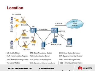
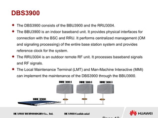
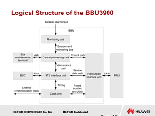
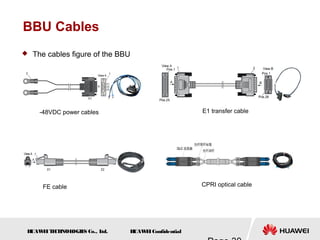
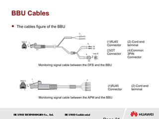
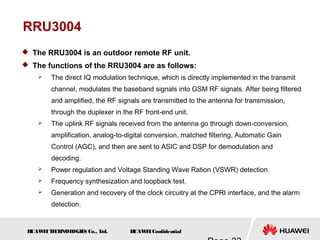
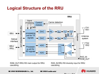
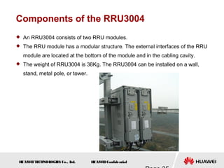
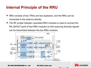
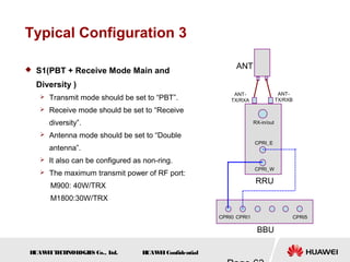
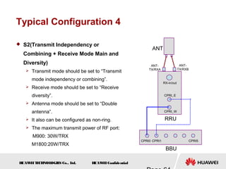
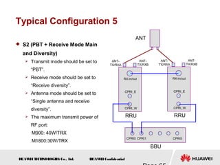
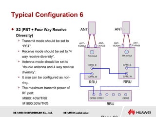
2008-03
www.huawei.com
H
UAW
E
IConfidential
Security Level: Internal Use
HUAWEI GSM DBS3900
Hardware Structure
H
UAW
E
IT
E
CH
NOL
OGIE
S Co., L
td. H
UAW
E
IConfidential
DBS3900 is a distributed BTS solution developed by Huawei
Technologies Co.,Ltd. Its baseband part and radio part can be
installed independently so that it can be used to various
environments with wide coverage and low cost.
H
UAW
E
IT
E
CH
NOL
OGIE
S Co., L
td. H
UAW
E
IConfidential
 Know the functions and features of DBS3900
 Master the Hardware structure and function of DBS3900
 Familiar with the Typical configuration and cable
connection of DBS3900
 Master the Network topologies of DBS3900
H
UAW
E
IT
E
CH
NOL
OGIE
S Co., L
td. H
UAW
E
IConfidential
 DBS3900 Electronic Documentation
 BBU3900 Quick Installation Guide
 RRU3004 Quick Installation Guide
 DBS3900 Deployment Guide
H
UAW
E
IT
E
CH
NOL
OGIE
S Co., L
td. H
UAW
E
IConfidential
Chapter 1 DBS3900 System Description
Chapter 2 DBS3900 Hardware Structure
Chapter 3 DBS3900 Typical Configuration
Chapter 4 DBS3900 Network Topologies
H
UAW
E
IT
E
CH
NOL
OGIE
S Co., L
td. H
UAW
E
IConfidential
Location
PSTN
ISDN
PSPDN
Um Interface
DBS3900
DBS3900
DBS3900
BTS
OMC
HLR/AUC/EIR
BSC
MSC/VLR
SMC/VM
A Interface
MAP
M
AP
TUP,ISUP
MS
MS
MS
MS: Mobile Station BTS: Base Transceiver Station BSC: Base Station Controller
HLR: Home Location Register AUC: Authentication Center EIR: Equipment Identity Register
MSC: Mobile Switching Center VLR: Visitor Location Register SMC: Short Message Center
VM: Voice Mailbox OMC: Operation and Maintenance Center DBS : Distributed Base Station
H
UAW
E
IT
E
CH
NOL
OGIE
S Co., L
td. H
UAW
E
IConfidential
Functions and Features
 Wide coverage, low cost
 Suitable for various environments, flexible installation
 Support PGSM900M 、 EGSM900 、 DCS1800M
 One RRU module can support 2 TRXs
 Support transmit diversity
 Support PBT
 Support four-way receive diversity over different RRU
 BBU support star, tree, chain and ring topology
 Calculate TA exactly
 Support GPRS and EGPRS
H
UAW
E
IT
E
CH
NOL
OGIE
S Co., L
td. H
UAW
E
IConfidential
Functions and Features
 Support Omni-directional coverage and directional coverage
 One BBU can support 36TRX at most and 12 cells at most
 Support A5/3, A5/2, A5/1 encryption and decryption
 Support dynamic radio frequency management
 Cell broadcasting service and point-to-point short message
 Support mixed combining with BTS3012
 Support -48VDC power input
H
UAW
E
IT
E
CH
NOL
OGIE
S Co., L
td. H
UAW
E
IConfidential
Chapter 1 DBS3900 System Description
Chapter 2 DBS3900 Hardware Structure
Chapter 3 DBS3900 Typical Configuration
Chapter 4 DBS3900 Network Topologies
H
UAW
E
IT
E
CH
NOL
OGIE
S Co., L
td. H
UAW
E
IConfidential
Abbreviation
RRU Remote Radio unit
BBU Base Band unit
GTMU Transmission& Timing& Management Unit for BBU
UPEA
Universal power and Environment interface unit
Type A (-48v)
BSBC Universal BBU Subrack Backplane Type C (2U)
UBFA Universal BBU Fan Unit Type A (2U)
UEIU Universal Environment Interface unit
UELP Universal E1/T1 Lighting Protection unit
UFLP Universal FE/GE Lighting Protection unit
CPRI Common Protocol Radio Interface
APM Advanced Power Module
IBBS Integrated Backup Battery System
OFB Outdoor Facility Box
H
UAW
E
IT
E
CH
NOL
OGIE
S Co., L
td. H
UAW
E
IConfidential
Sector 1 DBS3900 Hardware Components
Sector 2 BBU3900 System Structure
Sector 3 RRU3004 System Structure
Sector 4 DBS3900 Typical Scenario
H
UAW
E
IT
E
CH
NOL
OGIE
S Co., L
td. H
UAW
E
IConfidential
DBS3900
 The DBS3900 consists of the BBU3900 and the RRU3004.
 The BBU3900 is an indoor baseband unit. It provides physical interfaces for
connection with the BSC and RRU. It performs centralized management (OM
and signaling processing) of the entire base station system and provides
reference clock for the system.
 The RRU3004 is an outdoor remote RF unit. It processes baseband signals
and RF signals.
 The Local Maintenance Terminal (LMT) and Man-Machine Interactive (MMI)
can implement the maintenance of the DBS3900 through the BBU3900.
BBU3900
RR
U3004 RRU3004 RRU3004
H
UAW
E
IT
E
CH
NOL
OGIE
S Co., L
td. H
UAW
E
IConfidential
APM30 Overview
 The APM30 provides –48 V DC power
and power backup for the distributed
base stations and mini base stations,
and provides space for the user
equipment. It also performs functions
such as battery management and
monitoring, and lightning protection.
1. Filler panel(1U)
2. Power sub-rack (3 U)
3. DC PDU(2U)
4~8. Filler Panel(1U)
9. Space for batteries (3U)
H
UAW
E
IT
E
CH
NOL
OGIE
S Co., L
td. H
UAW
E
IConfidential
OFB Overview
 OFB (Outdoor Facility Box)
supports DC power input
and DC power distribution
and can serve as a cabinet
for the transmission
equipment, provides 11U
installation space.
 Since it has no heating
system, the OFB is unable
to adapt to low-temperature
environment. The OFB is
applicable to category C
environment.
H
UAW
E
IT
E
CH
NOL
OGIE
S Co., L
td. H
UAW
E
IConfidential
IBBS Overview
 As an auxiliary product for Huawei outdoor BTSs, the
Integrated Backup Battery System (IBBS) provides
backup power to meet the requirements for fast network
deployment.
 Output: -48V DC.
 Backup power mode: serial or parallel connection
between batteries.
 Operating temperature: The IBBS cabinet is functioning
normally when the temperature is +55°C.
 Alarm system: It provide door control, smog and
temperature sensors.
 A maximum of 16 batteries of 12 V 100 Ah or 2 V 150
Ah, four batteries in one group and four groups in the
IBBS cabinet.
H
UAW
E
IT
E
CH
NOL
OGIE
S Co., L
td. H
UAW
E
IConfidential
Sector 1 DBS3900 Hardware Components
Sector 2 BBU3900 System Structure
Sector 3 RRU3004 System Structure
Sector 4 DBS3900 Typical Scenario
H
UAW
E
IT
E
CH
NOL
OGIE
S Co., L
td. H
UAW
E
IConfidential
BBU3900
 The BBU3900 is an indoor BTS control unit that enables interaction
between the BTS and the BSC.
 The BBU3900 performs the following functions:
 Provides physical interfaces between the BTS and the BSC for
interaction.
 Provides CPRI ports for communication with the RRU3004.
 Provides the USB port for downloading the BTS software.
 Provides OM channels for connection to the LMT (or M2000).
 Processes UL and DL data.
 Provides centralized management on the entire DBS system, such as
OM and signaling processing.
 Provides the reference clock for the entire system.
H
UAW
E
IT
E
CH
NOL
OGIE
S Co., L
td. H
UAW
E
IConfidential
Logical Structure of the BBU3900
H
UAW
E
IT
E
CH
NOL
OGIE
S Co., L
td. H
UAW
E
IConfidential
Hardware Components of BBU3900
 The typical power consumption of the BBU is 35 W.
 The weight of the BBU isn’t more than 12KG.
 Each BBU3900 supports a maximum of 36 TRXs, and 12 cells.
 The BBU is a small box with all the external ports on the front panel.
 The BBU3900 boards consist of the BSBC, UEIU, GTMU, and UELP; the
BBU3900 modules consist of the UBFA and the UPEU.
H
UAW
E
IT
E
CH
NOL
OGIE
S Co., L
td. H
UAW
E
IConfidential
BSBC Board
 The BSBC is the backplane of the BBU. The BSBC provides eight
board slots, two power slots, and one fan slot.
 The universal BBU sub-rack backplane type C (2U) (BSBC) provides
backplane interfaces for communication between boards and supplies
power for boards.
 The GTMU is located in slots 5 and 6, slot 7 for a main control board
that supports 3G, and other ports as common slots.
H
UAW
E
IT
E
CH
NOL
OGIE
S Co., L
td. H
UAW
E
IConfidential
GTMU Board
 The GSM transmission, timing, and management unit for BBU (GTMU)
controls and manages the entire BTS. It provides interfaces related to the
reference clock, power supply, OM, and external alarm collection.
 The GTMU performs the following functions:
 Controls, maintains, and operates the BTS
 Supports fault management, configuration management, performance
management, and security management
 Monitors the fan module and the power supply module
 Distributes and manages BTS clock signals
 Provides clock input for testing
 Provides the Ethernet port for terminal maintenance
 Supports four E1 inputs
 Provides the CPRI ports for communication with the RRU
H
UAW
E
IT
E
CH
NOL
OGIE
S Co., L
td. H
UAW
E
IConfidential
GTMU Board
 Ports on the GTMU Panel
Port Type Cable Description
CPRI0–
CPRI5
DLC
connector
CPRI optical cable
between the BBU
and the RRU
Provides the input and output of the optical signals
ETH RJ45
connector
Crossover cable
(delivered with the
equipment)
Performs local maintenance and commissioning
FE0 RJ45
connector
- A reserved port that performs the following function:
Connects the BBU to a routing device in the equipment room
through the Ethernet cable to transmit network information
FE1 DLC
connector
- A reserved port that performs the following function:
Connects the BBU to a routing device in the equipment room
through the optical cable to transmit network information
USB USB
connector
- A reserved port that performs the following function:
Automatically upgrades the software through the USB disk
TST USB
connector
- Tests the output clock signals with a tester
E1/T1 DB26 male
connector
E1/T1 cable of the
BBU
Provides the input and output of the four E1/T1 signals
between the GTMU and the UELP or between the GTMU and
the BSC
H
UAW
E
IT
E
CH
NOL
OGIE
S Co., L
td. H
UAW
E
IConfidential
GTMU Board
 LEDs on the GTMU Panel
LED Color Status Description
RUN Green On The board is faulty.
Off There is no power supply or the board is faulty.
Blinking once/2s The board is operational.
Blinking once/4s The OML link is abnormal.
Blinking four
times/s
The board is loading software.
ALM Red On A fault occurs in the running board.
Off An alarm is not generated.
ACT Green On The board is operational.
Off The board is faulty.
LIU0–LIU3 Green On A local E1/T1 alarm is generated.
Blinking four
times/s
A remote E1/T1 alarm is generated.
Off This link is not used or the alarm is cleared.
CPRI0-CPRI5 Green On The CPRI link is functional.
Red On The reception of the optical module is abnormal and an alarm
is triggered.
H
UAW
E
IT
E
CH
NOL
OGIE
S Co., L
td. H
UAW
E
IConfidential
GTMU Board
 DIP Switch of GTMU
DIP
switch
DIP status Description
1 2
SW1 ON ON The E1 impedance is
set to 75 Ω.
OFF ON The E1 impedance is
set to 120 Ω.
ON OFF The T1 impedance is
set to 100 Ω.
DIP
switch
DIP status Description
1 2 3 4
SW2 ON ON ON ON The E1 cable
is grounded.
OFF OFF OFF OFF The E1 cable
is not
grounded.
DIP
switch
DIP status Description
1 2 3 4
SW4 ON ON ON ON The E1 link can be
bypassed.
OFF OFF OFF OFF The E1 link cannot be
bypassed.
SW5 ON ON ON ON The E1 link cannot be
bypassed.
OFF ON ON OFF The E1 link of the Level
1 cascaded BTS can be
bypassed.
ON OFF ON OFF The E1 link of the Level
2 cascaded BTS can be
bypassed.
OFF OFF ON OFF The E1 link of the Level
3 cascaded BTS can be
bypassed.
ON ON OFF OFF The E1 link of the Level
4 cascaded BTS can be
bypassed.
OFF ON OFF OFF The E1 link of the Level
5 cascaded BTS can be
bypassed.
H
UAW
E
IT
E
CH
NOL
OGIE
S Co., L
td. H
UAW
E
IConfidential
UBFA Module
 The universal BBU fan unit type A (2U) (UBFA) communicates with the
GTMU to regulate the temperature, adjust the fan speed, and report
alarms. The UBFA module is hot swappable.
LED Color Status Description
STATE Green Blinking twice per
second
The board is not securely
connected. An alarm is not
generated.
Red On An alarm is generated.
Green Blinking once
every two
seconds
The board operates normally.
H
UAW
E
IT
E
CH
NOL
OGIE
S Co., L
td. H
UAW
E
IConfidential
UPEU Module
 The universal power and environment interface unit type A (–48 V) (UPEU)
supports the –48 V DC power input, supplies power to the boards, modules,
and fan in the BBU, and provides access to multiple environment monitoring
signals. Port Type Description
MON0 RJ45
Connector
Provides the input and output of the
externally collected environment
monitoring signals to the GTMU
according to the RS485 communications
protocol
MON1 RJ45
Connector
Reserved
EXT-
ALM0
RJ45
Connector
Transmits the externally collected
environment monitoring signals to the
GTMU through communications protocol
related to the dry contact
EXT-
ALM1
RJ45
Connector
Reserved
PWR 3V3Power
Connector
–48V power input
H
UAW
E
IT
E
CH
NOL
OGIE
S Co., L
td. H
UAW
E
IConfidential
UEIU Board
 The universal environment interface unit (UEIU) supports multiple
environment monitoring signals. The UEIU supports eight Boolean
alarm signals and two RS485 environment monitoring signals.
 The UEIU is optional. It is configured when the environment interfaces
are insufficient.
Port Type Description
MON0 RJ45
Connector
Provides the input and output of the
externally collected environment
monitoring signals to the GTMU
according to the RS485
communications protocol
MON1 RJ45
Connector
Reserved
EXT-
ALM0
RJ45
Connector
Transmits the externally collected
environment monitoring signals to the
GTMU through communications
protocol related to the dry contact
EXT-
ALM1
RJ45
Connector
Reserved
H
UAW
E
IT
E
CH
NOL
OGIE
S Co., L
td. H
UAW
E
IConfidential
UELP Board
 The universal E1/T1 lightning protection unit (UELP) provides lightning
protection for four E1/T1 signals.
Port Type Cable Description
INSIDE DB25 male connector E1 transfer cable
of the BBU
Transfers the four E1/T1 signals between the
UELP and the GTMU
OUTSIDE DB26male connector E1/T1 cables of
the BBU
Provides the input and output of the four
E1/T1 signals between the BBU and the BSC
DIP Switch DIP Status Description
1 2 3 4
SW1 OFF OFF OFF OFF Twisted-pair cable ( 100Ω T1 or 120Ω E1 )
ON OFF ON OFF Coaxial cable ( 75Ω E1 )
 UELP Board provides a DIP switch to set impedance of E1/T1.
H
UAW
E
IT
E
CH
NOL
OGIE
S Co., L
td. H
UAW
E
IConfidential
BBU Cables
 The BBU3900 cables are classified into the PGND cable, –48 V DC
power cable, E1/T1 cable, E1 transfer cable, RS485 environment
monitoring signal cable, CPRI signal cable between the BBU and the
RRU, and BBU monitoring signal cable.
 The cable connection relations of the BBU as following:
H
UAW
E
IT
E
CH
NOL
OGIE
S Co., L
td. H
UAW
E
IConfidential
BBU Cables
 The cables figure of the BBU
-48VDC power cables E1 transfer cable
FE cable CPRI optical cable
H
UAW
E
IT
E
CH
NOL
OGIE
S Co., L
td. H
UAW
E
IConfidential
BBU Cables
 The cables figure of the BBU
(1)RJ45
Connector
(2) Cord end
terminal
Monitoring signal cable between the OFB and the BBU
Monitoring signal cable between the APM and the BBU
(1)RJ45
Connector
(2) Cord end
terminal
(3)OT
Connector
(4)Common
3PIN
Connector
H
UAW
E
IT
E
CH
NOL
OGIE
S Co., L
td. H
UAW
E
IConfidential
Sector 1 DBS3900 Hardware Components
Sector 2 BBU3900 System Structure
Sector 3 RRU3004 System Structure
Sector 4 DBS3900 Typical Scenario
H
UAW
E
IT
E
CH
NOL
OGIE
S Co., L
td. H
UAW
E
IConfidential
RRU3004
 The RRU3004 is an outdoor remote RF unit.
 The functions of the RRU3004 are as follows:
 The direct IQ modulation technique, which is directly implemented in the transmit
channel, modulates the baseband signals into GSM RF signals. After being filtered
and amplified, the RF signals are transmitted to the antenna for transmission,
through the duplexer in the RF front-end unit.
 The uplink RF signals received from the antenna go through down-conversion,
amplification, analog-to-digital conversion, matched filtering, Automatic Gain
Control (AGC), and then are sent to ASIC and DSP for demodulation and
decoding.
 Power regulation and Voltage Standing Wave Ration (VSWR) detection.
 Frequency synthesization and loopback test.
 Generation and recovery of the clock circuitry at the CPRI interface, and the alarm
detection.
H
UAW
E
IT
E
CH
NOL
OGIE
S Co., L
td. H
UAW
E
IConfidential
Logical Structure of the RRU
RXM_OUT:RRU RX main output for RRU
cascading
RXD_IN:RRU RX diversity input for RRU
cascading
H
UAW
E
IT
E
CH
NOL
OGIE
S Co., L
td. H
UAW
E
IConfidential
Components of the RRU3004
 An RRU3004 consists of two RRU modules.
 The RRU module has a modular structure. The external interfaces of the RRU
module are located at the bottom of the module and in the cabling cavity.
 The weight of RRU3004 is 38Kg. The RRU3004 can be installed on a wall,
stand, metal pole, or tower.
H
UAW
E
IT
E
CH
NOL
OGIE
S Co., L
td. H
UAW
E
IConfidential
RRU Module
 The RRU module has a bottom panel, a cabling cavity panel, and an
area attached with LEDs.
 Provides - 48VDC power supply.
1 Bottom panel
2 Cabling cavity panel
3 LEDs
H
UAW
E
IT
E
CH
NOL
OGIE
S Co., L
td. H
UAW
E
IConfidential
RRU Module
 Ports of the RRU Module
Item Label Description
Bottom panel RX_IN/OUT Interconnection ports for RF signals
RET RET antenna port
ANT_TX/RXA RF TX/RX port A
ANT_TX/RXB RF TX/RX port B
Cabling cavity
panel
RTN+ Power wire post
NEG-
TX RX CPRI_E Eastern optical port
TX RX CPRI_W Western optical port
EXT_ALM Alarm Port
RST Hardware reset button
TST VSWR Test button for VSWR alarms
TST CPRI Test button for the CPRI port
H
UAW
E
IT
E
CH
NOL
OGIE
S Co., L
td. H
UAW
E
IConfidential
RRU Module
 LEDs on the RRU Module
LED Status Meaning
RUN On The board is faulty.
Off No power input is available.
Blinking once every two seconds The board is operational.
ALM On (blinking at high frequency) There is a fault related to the running board.
Off No alarm is detected.
ACT On Normal operation
Off The connection with the BBU is not established.
Blinking once every two seconds Only one logical transceiver is functional (including TRX mutual aid is
implemented).
Blinking twice per second Local test status
VSWR TX_ACT On (green) No VSWR alarm is detected.
Blinking once every two seconds (green) The board is operational.
Blinking once every two seconds (red) A VSWR alarm is detected at the ANT_TX/RXA port.
Blinking once per second (red) A VSWR alarm is detected at the ANT_TX/RXB port.
On (red) A VSWR alarm is detected at the ANT_TX/RXA and ANT_TX/RXB ports.
OPTW/E(westwar
d/eastward CPRI
LED )
On (green) The CPRI link is functional.
On (red) The reception of the optical module is abnormal and an alarm is
triggered.
Blinking once every two seconds (red) The CPRI link is out of lock.
Off The SFP module is out-of-position or the optical module is powered off.
H
UAW
E
IT
E
CH
NOL
OGIE
S Co., L
td. H
UAW
E
IConfidential
Connections of RRU Cables
 The RRU3004 has the following cables: PGND cable, power cable,
AISG multi-wire cable, AISG extension cable, CPRI optical cable, RF
jumpers, Boolean input cable, and cables for cascaded RRUs.
H
UAW
E
IT
E
CH
NOL
OGIE
S Co., L
td. H
UAW
E
IConfidential
Connections of RRU Cables
 The related cable’s figure of the RRU
RRU –48 V DC power cable RRU Power cable for cascaded RRU modules
Signal cable between the electrical
ports on cascaded RRU modules
CPRI optical cable
H
UAW
E
IT
E
CH
NOL
OGIE
S Co., L
td. H
UAW
E
IConfidential
Connections of RRU Cables
 The related cable’s figure of the RRU
Cascaded RF jumper Boolean input cable
AISG multi-wire cable AISG extension cable
H
UAW
E
IT
E
CH
NOL
OGIE
S Co., L
td. H
UAW
E
IConfidential
Sector 1 DBS3900 Hardware Components
Sector 2 BBU3900 System Structure
Sector 3 RRU3004 System Structure
Sector 4 DBS3900 Typical Scenario
H
UAW
E
IT
E
CH
NOL
OGIE
S Co., L
td. H
UAW
E
IConfidential
Typical Scenarios of the DBS3900
 Scenario 1: BBU+RRU+APM+IBBS
 When the site provides only the AC power supply and a long-time backup power
supply is required, the installation scenario can be used.
 The BBU can be installed in the APM. The APM supplies -48 V DC power to the BBU and
RRU.
 The IBBS can supply backup power to the BTS for a long time to ensure that the BTS still
operates normally in the case of an AC power supply failure.
 The RRU can be installed on a stand, pole, wall, or tower.
H
UAW
E
IT
E
CH
NOL
OGIE
S Co., L
td. H
UAW
E
IConfidential
Typical Scenarios of the DBS3900
 Scenario 2: BBU+RRU+APM+OFB
 When the site provides the AC power supply and the space in the APM is
insufficient, the installation scenario can be used.
 The OFB provides 5 U to 11 U transmission space in which transmission equipment or
batteries can be installed.
 The BBU can be configured in the APM. The APM supplies –48 V DC power to the BBU
and RRU and also provides backup DC power.
H
UAW
E
IT
E
CH
NOL
OGIE
S Co., L
td. H
UAW
E
IConfidential
Typical Scenarios of the DBS3900
 Scenario 3: BBU+RRU+OFB
 When there is no equipment room on site, the DC power supply is available, and
the backup power supply is not required, the installation scenario can be used.
 The BBU is installed in the OFB. The OFB supplies –48 V DC power to the BBU and
RRU.
H
UAW
E
IT
E
CH
NOL
OGIE
S Co., L
td. H
UAW
E
IConfidential
Chapter 1 DBS3900 System Description
Chapter 2 DBS3900 Hardware Structure
Chapter 3 DBS3900 Typical Configuration
Chapter 4 DBS3900 Network Topologies
H
UAW
E
IT
E
CH
NOL
OGIE
S Co., L
td. H
UAW
E
IConfidential
Sector 1 RRU Work Mode Introduction
Sector 2 RRU Typical Configuration
H
UAW
E
IT
E
CH
NOL
OGIE
S Co., L
td. H
UAW
E
IConfidential
Internal Principle of the RRU
 RRU consists of two TRXs and two duplexers, and the RRU can be
connected to the antenna directly.
 The RF jumper between cascaded RRU modules is used to connect the
RX_IN/OUT ports of two RRU modules so that receiving diversity signals
can be transmitted between the two RRU modules.
H
UAW
E
IT
E
CH
NOL
OGIE
S Co., L
td. H
UAW
E
IConfidential
The Antenna Configuration of the RRU
 Single antenna
 There is no receiving diversity or transmitting diversity.
 Single antenna and double receivers
 The RRU module has one TX/RX feeder and two way receiving diversities, one of
the receiver is from the another RRU module of the RRU3004.
 Double antennas
 The RRU module has two TX/RX feeders and two way receiving diversities.
 Double antennas and four receivers
 Each RRU can have two TX/RX feeders, and two RRUs are combined to support
four way receive diversity.
H
UAW
E
IT
E
CH
NOL
OGIE
S Co., L
td. H
UAW
E
IConfidential
RRU Power Mode
 M900 RRU
 Optional value: “30W”,“25W”,“15W”,“12W”.
 Default value: “15W”, RRU supports transmit combining or independency here,
otherwise RRU supports transmit independency only.
 M1800 RRU
 Optional value :”20W”, “10W”.
 Default value: “10W”, RRU supports transmit combining or independency here,
otherwise RRU supports transmit independency only.
H
UAW
E
IT
E
CH
NOL
OGIE
S Co., L
td. H
UAW
E
IConfidential
RRU Transmit Mode and Receive Mode
 RRU transmit mode
 Transmit combining or independency
 PBT
 Transmit diversity
 RRU receive mode
 Receive diversity
 Four way receive diversity
H
UAW
E
IT
E
CH
NOL
OGIE
S Co., L
td. H
UAW
E
IConfidential
Cell Configuration of Single RRU
 S1
 Configure only one TRX in one RRU.
 Optional TRX work mode: “Transmit combining or independency”, “PBT”,
“Transmit diversity”, ”Receive diversity“, ”Four way receive diversity”.
 S2
 Two TRXs of RRU are configured in a S2 cell.
 Optional TRX work mode: ” Transmit combining or independency “, ”Receive
diversity”.
 S1/1
 Two TRXs of RRU are configured in two S1 cells.
 Optional TRX work mode: ” Transmit combining or independency “, ” Receive
diversity“.
 Actually, the TRX only have single receiving channel.
H
UAW
E
IT
E
CH
NOL
OGIE
S Co., L
td. H
UAW
E
IConfidential
Combination Solution of Two RRUs
 Two RRUs are combined to share receive and transmit channels so that
the configuration is more flexible. In the following figure, the cable
between CPRI_W and CPRI_E are used for the TRX baseband signal
interconnection, while RX_IN/OUT is only used for two way receiving
diversity between two RRUs.
Interface
Processing
Unit
DUP
DUP
CPRI-E
CPRI-W
ANTA
ANTB
RX-IN
RX_OUT
Interface
Processing
Unit
DUP
DUP
CPRI-E
CPRI-W
ANTA
ANTB
RX-IN
RX_OUT
H
UAW
E
IT
E
CH
NOL
OGIE
S Co., L
td. H
UAW
E
IConfidential
RRU Transmit Mode-Transmit Combining
or Independency
 In this mode, two TRXs of RRU are both work.
 In this mode, the system will work on the transmit independency or transmit
combining mode automatically, according to the power mode and antenna
mode.
 In transmit dependency mode, TRX0 occupies channel A while TRX1 occupies
channel B.
 In transmit combining mode, the combining signal are transmitted through
channel A.
H
UAW
E
IT
E
CH
NOL
OGIE
S Co., L
td. H
UAW
E
IConfidential
RRU Transmit Mode-Transmit Combining
or Independency
 Transmit independency
 Transmit combining
Interface
Processing
Unit
DUP
DUP
CPRI-E
CPRI-W
ANTA
ANTB
Interface
Processing
Unit
DUP
DUP
CPRI-E
CPRI-W
ANTA
ANTB
H
UAW
E
IT
E
CH
NOL
OGIE
S Co., L
td. H
UAW
E
IConfidential
RRU Transmit Mode-PBT
 In PBT mode, only the first TRX can work.
 PBT mode can improve the transmitting power to 40W.
 In PBT mode, downlink signal are transmitted through channel A.
Interface
Processing
Unit
DUP
DUP
CPRI-E
CPRI-W
ANTA
ANTB
H
UAW
E
IT
E
CH
NOL
OGIE
S Co., L
td. H
UAW
E
IConfidential
RRU Transmit Mode-Transmit Diversity
 In this mode, only the first TRX can work.
 Transmit diversity mode can improve signal the quality of downlink signal.
 In this mode, the signal from the first TRX will be divided to two channels and
be transmitted through channel A and channel B.
Interface
Processing
Unit
DUP
DUP
CPRI-E
CPRI-W
ANTA
ANTB
H
UAW
E
IT
E
CH
NOL
OGIE
S Co., L
td. H
UAW
E
IConfidential
RRU Receive Mode-Main and Diversity
 Receive diversity, RRU can work as double TRX mode.
 Each TRX can receive the signal from two feeders.
 In the following figure , the TRX gets the receiving signal from channel A and
B of the single RRU.
 It is also possible for TRX to use the channel A receiver of the other RRU in
two RRUs combining solution.
Interface
Processing
Unit
DUP
DUP
CPRI-E
CPRI-W
ANTA
ANTB
RX-IN
RX_OUT
The second
receiving
diversity
signal may
come from
second RRU
H
UAW
E
IT
E
CH
NOL
OGIE
S Co., L
td. H
UAW
E
IConfidential
RRU Receive Mode-Four Way Receive
Diversity
 In this mode, only the first TRX can work.
 The working TRX gets the uplink signal from four feeders of two RRUs.
 Only the antenna mode “Double Antennas, Four Receivers” can support “Four
way receive diversity”.
Interface
Processing
DUP
CPRI-E
CPRI-W
ANTA
ANTB
RX-IN
RX_OUT
Interface
Processing
DUP
CPRI-E
CPRI-W
ANTA
ANTB
RX-IN
RX_OUT
The other two
receiving
diversity
signal come
from second
RRU
H
UAW
E
IT
E
CH
NOL
OGIE
S Co., L
td. H
UAW
E
IConfidential
Sector 1 RRU Work Mode Introduction
Sector 2 RRU Typical Configuration
H
UAW
E
IT
E
CH
NOL
OGIE
S Co., L
td. H
UAW
E
IConfidential
Typical Configuration 1
 S1(Transmit Diversity or Transmit
Independency + Receive Mode Main
and Diversity )
 Transmit mode should be set to
“Transmit Independency or combining”
 Receive mode should be set to “Receive
diversity”.
 Antenna mode should be set to” Double
Antenna”.
 It also can be configured as non-ring.
 The maximum transmit power of RF port:
M900: 30W/TRX
M1800:20W/TRX.
BBU
CPRI5
CPRI0 CPRI1
RRU
CPRI_E
CPRI_W
RX-in/out
ANT-
TX/RXB
ANT-
TX/RXA
ANT
H
UAW
E
IT
E
CH
NOL
OGIE
S Co., L
td. H
UAW
E
IConfidential
Typical Configuration 2
 S1(Transmit Diversity + Receive Mode
Main and Diversity )
 Transmit mode should be set to“Transmit
diversity”.
 Receive mode should be set to“Receive
diversity”.
 Antenna mode should be set to “Double
antenna”.
 It also can be configured as non-ring.
 The maximum transmit power of RF port:
M900: 20W/TRX
M1800:15W/TRX
BBU
CPRI5
CPRI0 CPRI1
RRU
CPRI_E
CPRI_W
RX-in/out
ANT-
TX/RXB
ANT-
TX/RXA
ANT
H
UAW
E
IT
E
CH
NOL
OGIE
S Co., L
td. H
UAW
E
IConfidential
Typical Configuration 3
 S1(PBT + Receive Mode Main and
Diversity )
 Transmit mode should be set to “PBT”.
 Receive mode should be set to “Receive
diversity”.
 Antenna mode should be set to “Double
antenna”.
 It also can be configured as non-ring.
 The maximum transmit power of RF port:
M900: 40W/TRX
M1800:30W/TRX
BBU
CPRI5
CPRI0 CPRI1
RRU
CPRI_E
CPRI_W
RX-in/out
ANT-
TX/RXB
ANT-
TX/RXA
ANT
H
UAW
E
IT
E
CH
NOL
OGIE
S Co., L
td. H
UAW
E
IConfidential
Typical Configuration 4
 S2(Transmit Independency or
Combining + Receive Mode Main and
Diversity)
 Transmit mode should be set to “Transmit
mode independency or combining”.
 Receive mode should be set to “Receive
diversity”.
 Antenna mode should be set to “Double
antenna”.
 It also can be configured as non-ring.
 The maximum transmit power of RF port:
M900: 30W/TRX
M1800:20W/TRX
BBU
CPRI5
CPRI0 CPRI1
RRU
CPRI_E
CPRI_W
RX-in/out
ANT-
TX/RXB
ANT-
TX/RXA
ANT
H
UAW
E
IT
E
CH
NOL
OGIE
S Co., L
td. H
UAW
E
IConfidential
Typical Configuration 5
 S2 (PBT + Receive Mode Main
and Diversity)
 Transmit mode should be set to
“PBT”.
 Receive mode should be set to
“Receive diversity”.
 Antenna mode should be set to
“Single antenna and receive
diversity”.
 The maximum transmit power of
RF port:
M900: 40W/TRX
M1800:30W/TRX
RRU
CPRI_E
CPRI_W
RX-in/out
ANT-
TX/RXB
ANT-
TX/RXA
ANT
BBU
CPRI5
CPRI0 CPRI1
RRU
CPRI_E
CPRI_W
RX-in/out
ANT-
TX/RXB
ANT-
TX/RXA
H
UAW
E
IT
E
CH
NOL
OGIE
S Co., L
td. H
UAW
E
IConfidential
Typical Configuration 6
 S2 (PBT + Four Way Receive
Diversity)
 Transmit mode should be set to
“PBT”.
 Receive mode should be set to “4
way receive diversity”.
 Antenna mode should be set to
“double antenna and 4 way receive
diversity”.
 It also can be configured as non-
ring.
 The maximum transmit power of
RF port:
M900: 40W/TRX
M1800:30W/TRX
RRU
CPRI_E
CPRI_W
RX-in/out
ANT-
TX/RXB
ANT-
TX/RXA
ANT
BBU
CPRI5
CPRI0 CPRI1
RRU
CPRI_E
CPRI_W
RX-in/out
ANT-
TX/RXB
ANT-
TX/RXA
ANT
H
UAW
E
IT
E
CH
NOL
OGIE
S Co., L
td. H
UAW
E
IConfidential
Typical Configuration 7
 S4 (Transmit Combining +
Receive Mode Main and
Diversity)
 Transmit mode should be set to
“Transmit combining or
independency”
 Receive mode should be set to
“Receive diversity”
 Antenna mode should be set to
“Single antenna and two receive”
 The maximum transmit power of
RF port:
M900: 15W/TRX
M1800:10W/TRX
RRU
CPRI_E
CPRI_W
RX-in/out
ANT-
TX/RXB
ANT-
TX/RXA
ANT
BBU
CPRI5
CPRI0 CPRI1
RRU
CPRI_E
CPRI_W
RX-in/out
ANT-
TX/RXB
ANT-
TX/RXA
H
UAW
E
IT
E
CH
NOL
OGIE
S Co., L
td. H
UAW
E
IConfidential
Typical Configuration 8
 S8(Transmit Combining + Receive
Mode Main and Diversity)
 Transmit mode should be set to
“Transmit combining or
independency”.
 Receive mode should be set to
“Receive diversity”.
 Antenna mode should be set to
“Single antenna and two receive”.
 Actually It is combined by two S4.
 The maximum transmit power of RF
port:
M900: 15W/TRX
M1800:10W/TRX
ANT-
TX/RXA
CPR
I5
CPR
I0
CPR
I1
AN
T
BB
U
RR
U
CPRI
_E
CPRI_
W
RX-
in/out
ANT-
TX/RX
B
ANT-
TX/RX
A
RR
U
CPRI
_E
CPRI_
W
RX-
in/out
ANT-
TX/RX
B
AN
T
RR
U
CPRI
_E
CPRI_
W
RX-
in/out
ANT-
TX/RX
B
ANT-
TX/RX
A
RR
U
CPRI_
E
CPRI_
W
RX-
in/out
ANT-
TX/RX
B
ANT-
TX/RX
A
H
UAW
E
IT
E
CH
NOL
OGIE
S Co., L
td. H
UAW
E
IConfidential
Chapter 1 DBS3900 System Description
Chapter 2 DBS3900 Hardware Structure
Chapter 3 DBS3900 Typical Configuration
Chapter 4 DBS3900 Network Topologies
H
UAW
E
IT
E
CH
NOL
OGIE
S Co., L
td. H
UAW
E
IConfidential
DBS3900 Network Topologies
 Network Topologies of the BBU
 The BSC and BBUs support multiple network topologies: star, chain, tree, and ring.
 E1/T1 can be used to connect BBU and BSC, or interconnect transmission
equipment, optical fiber and FE cable can be used to connect BBU and Router.
 Network Topologies of the RRU
 The BBU and RRUs support two network topologies: star and chain.
 RRU connect with BBU by optical fiber.
H
UAW
E
IT
E
CH
NOL
OGIE
S Co., L
td. H
UAW
E
IConfidential
Network Topologies of the BBU
 The BSC and BBUs support multiple network topologies: star, chain,
tree, and ring.
H
UAW
E
IT
E
CH
NOL
OGIE
S Co., L
td. H
UAW
E
IConfidential
Network Topologies of the RRU
 The BBU and RRUs support two network topologies: star and chain.
H
UAW
E
IT
E
CH
NOL
OGIE
S Co., L
td. H
UAW
E
IConfidential
Summary
 DBS3900 function and features.
 DBS3900 hardware structure, include BBU and RRU etc.
 The work mode and typical configuration of the RRU.
 Network Topologies of the BBU and RRU.
Thank You
www.huawei.com

Huawei DBS 3900 Hardware Structure

  • 1.
  • 2.
    H UAW E IT E CH NOL OGIE S Co., L td.H UAW E IConfidential DBS3900 is a distributed BTS solution developed by Huawei Technologies Co.,Ltd. Its baseband part and radio part can be installed independently so that it can be used to various environments with wide coverage and low cost.
  • 3.
    H UAW E IT E CH NOL OGIE S Co., L td.H UAW E IConfidential  Know the functions and features of DBS3900  Master the Hardware structure and function of DBS3900  Familiar with the Typical configuration and cable connection of DBS3900  Master the Network topologies of DBS3900
  • 4.
    H UAW E IT E CH NOL OGIE S Co., L td.H UAW E IConfidential  DBS3900 Electronic Documentation  BBU3900 Quick Installation Guide  RRU3004 Quick Installation Guide  DBS3900 Deployment Guide
  • 5.
    H UAW E IT E CH NOL OGIE S Co., L td.H UAW E IConfidential Chapter 1 DBS3900 System Description Chapter 1 DBS3900 System Description Chapter 2 DBS3900 Hardware Structure Chapter 3 DBS3900 Typical Configuration Chapter 4 DBS3900 Network Topologies
  • 6.
    H UAW E IT E CH NOL OGIE S Co., L td.H UAW E IConfidential Location PSTN ISDN PSPDN Um Interface DBS3900 DBS3900 DBS3900 BTS OMC HLR/AUC/EIR BSC MSC/VLR SMC/VM A Interface MAP M AP TUP,ISUP MS MS MS MS: Mobile Station BTS: Base Transceiver Station BSC: Base Station Controller HLR: Home Location Register AUC: Authentication Center EIR: Equipment Identity Register MSC: Mobile Switching Center VLR: Visitor Location Register SMC: Short Message Center VM: Voice Mailbox OMC: Operation and Maintenance Center DBS : Distributed Base Station
  • 7.
    H UAW E IT E CH NOL OGIE S Co., L td.H UAW E IConfidential Functions and Features  Wide coverage, low cost  Suitable for various environments, flexible installation  Support PGSM900M 、 EGSM900 、 DCS1800M  One RRU module can support 2 TRXs  Support transmit diversity  Support PBT  Support four-way receive diversity over different RRU  BBU support star, tree, chain and ring topology  Calculate TA exactly  Support GPRS and EGPRS
  • 8.
    H UAW E IT E CH NOL OGIE S Co., L td.H UAW E IConfidential Functions and Features  Support Omni-directional coverage and directional coverage  One BBU can support 36TRX at most and 12 cells at most  Support A5/3, A5/2, A5/1 encryption and decryption  Support dynamic radio frequency management  Cell broadcasting service and point-to-point short message  Support mixed combining with BTS3012  Support -48VDC power input
  • 9.
    H UAW E IT E CH NOL OGIE S Co., L td.H UAW E IConfidential Chapter 1 DBS3900 System Description Chapter 2 DBS3900 Hardware Structure Chapter 2 DBS3900 Hardware Structure Chapter 3 DBS3900 Typical Configuration Chapter 4 DBS3900 Network Topologies
  • 10.
    H UAW E IT E CH NOL OGIE S Co., L td.H UAW E IConfidential Abbreviation RRU Remote Radio unit BBU Base Band unit GTMU Transmission& Timing& Management Unit for BBU UPEA Universal power and Environment interface unit Type A (-48v) BSBC Universal BBU Subrack Backplane Type C (2U) UBFA Universal BBU Fan Unit Type A (2U) UEIU Universal Environment Interface unit UELP Universal E1/T1 Lighting Protection unit UFLP Universal FE/GE Lighting Protection unit CPRI Common Protocol Radio Interface APM Advanced Power Module IBBS Integrated Backup Battery System OFB Outdoor Facility Box
  • 11.
    H UAW E IT E CH NOL OGIE S Co., L td.H UAW E IConfidential Sector 1 DBS3900 Hardware Components Sector 1 DBS3900 Hardware Components Sector 2 BBU3900 System Structure Sector 3 RRU3004 System Structure Sector 4 DBS3900 Typical Scenario
  • 12.
    H UAW E IT E CH NOL OGIE S Co., L td.H UAW E IConfidential DBS3900  The DBS3900 consists of the BBU3900 and the RRU3004.  The BBU3900 is an indoor baseband unit. It provides physical interfaces for connection with the BSC and RRU. It performs centralized management (OM and signaling processing) of the entire base station system and provides reference clock for the system.  The RRU3004 is an outdoor remote RF unit. It processes baseband signals and RF signals.  The Local Maintenance Terminal (LMT) and Man-Machine Interactive (MMI) can implement the maintenance of the DBS3900 through the BBU3900. BBU3900 RR U3004 RRU3004 RRU3004
  • 13.
    H UAW E IT E CH NOL OGIE S Co., L td.H UAW E IConfidential APM30 Overview  The APM30 provides –48 V DC power and power backup for the distributed base stations and mini base stations, and provides space for the user equipment. It also performs functions such as battery management and monitoring, and lightning protection. 1. Filler panel(1U) 2. Power sub-rack (3 U) 3. DC PDU(2U) 4~8. Filler Panel(1U) 9. Space for batteries (3U)
  • 14.
    H UAW E IT E CH NOL OGIE S Co., L td.H UAW E IConfidential OFB Overview  OFB (Outdoor Facility Box) supports DC power input and DC power distribution and can serve as a cabinet for the transmission equipment, provides 11U installation space.  Since it has no heating system, the OFB is unable to adapt to low-temperature environment. The OFB is applicable to category C environment.
  • 15.
    H UAW E IT E CH NOL OGIE S Co., L td.H UAW E IConfidential IBBS Overview  As an auxiliary product for Huawei outdoor BTSs, the Integrated Backup Battery System (IBBS) provides backup power to meet the requirements for fast network deployment.  Output: -48V DC.  Backup power mode: serial or parallel connection between batteries.  Operating temperature: The IBBS cabinet is functioning normally when the temperature is +55°C.  Alarm system: It provide door control, smog and temperature sensors.  A maximum of 16 batteries of 12 V 100 Ah or 2 V 150 Ah, four batteries in one group and four groups in the IBBS cabinet.
  • 16.
    H UAW E IT E CH NOL OGIE S Co., L td.H UAW E IConfidential Sector 1 DBS3900 Hardware Components Sector 2 BBU3900 System Structure Sector 2 BBU3900 System Structure Sector 3 RRU3004 System Structure Sector 4 DBS3900 Typical Scenario
  • 17.
    H UAW E IT E CH NOL OGIE S Co., L td.H UAW E IConfidential BBU3900  The BBU3900 is an indoor BTS control unit that enables interaction between the BTS and the BSC.  The BBU3900 performs the following functions:  Provides physical interfaces between the BTS and the BSC for interaction.  Provides CPRI ports for communication with the RRU3004.  Provides the USB port for downloading the BTS software.  Provides OM channels for connection to the LMT (or M2000).  Processes UL and DL data.  Provides centralized management on the entire DBS system, such as OM and signaling processing.  Provides the reference clock for the entire system.
  • 18.
    H UAW E IT E CH NOL OGIE S Co., L td.H UAW E IConfidential Logical Structure of the BBU3900
  • 19.
    H UAW E IT E CH NOL OGIE S Co., L td.H UAW E IConfidential Hardware Components of BBU3900  The typical power consumption of the BBU is 35 W.  The weight of the BBU isn’t more than 12KG.  Each BBU3900 supports a maximum of 36 TRXs, and 12 cells.  The BBU is a small box with all the external ports on the front panel.  The BBU3900 boards consist of the BSBC, UEIU, GTMU, and UELP; the BBU3900 modules consist of the UBFA and the UPEU.
  • 20.
    H UAW E IT E CH NOL OGIE S Co., L td.H UAW E IConfidential BSBC Board  The BSBC is the backplane of the BBU. The BSBC provides eight board slots, two power slots, and one fan slot.  The universal BBU sub-rack backplane type C (2U) (BSBC) provides backplane interfaces for communication between boards and supplies power for boards.  The GTMU is located in slots 5 and 6, slot 7 for a main control board that supports 3G, and other ports as common slots.
  • 21.
    H UAW E IT E CH NOL OGIE S Co., L td.H UAW E IConfidential GTMU Board  The GSM transmission, timing, and management unit for BBU (GTMU) controls and manages the entire BTS. It provides interfaces related to the reference clock, power supply, OM, and external alarm collection.  The GTMU performs the following functions:  Controls, maintains, and operates the BTS  Supports fault management, configuration management, performance management, and security management  Monitors the fan module and the power supply module  Distributes and manages BTS clock signals  Provides clock input for testing  Provides the Ethernet port for terminal maintenance  Supports four E1 inputs  Provides the CPRI ports for communication with the RRU
  • 22.
    H UAW E IT E CH NOL OGIE S Co., L td.H UAW E IConfidential GTMU Board  Ports on the GTMU Panel Port Type Cable Description CPRI0– CPRI5 DLC connector CPRI optical cable between the BBU and the RRU Provides the input and output of the optical signals ETH RJ45 connector Crossover cable (delivered with the equipment) Performs local maintenance and commissioning FE0 RJ45 connector - A reserved port that performs the following function: Connects the BBU to a routing device in the equipment room through the Ethernet cable to transmit network information FE1 DLC connector - A reserved port that performs the following function: Connects the BBU to a routing device in the equipment room through the optical cable to transmit network information USB USB connector - A reserved port that performs the following function: Automatically upgrades the software through the USB disk TST USB connector - Tests the output clock signals with a tester E1/T1 DB26 male connector E1/T1 cable of the BBU Provides the input and output of the four E1/T1 signals between the GTMU and the UELP or between the GTMU and the BSC
  • 23.
    H UAW E IT E CH NOL OGIE S Co., L td.H UAW E IConfidential GTMU Board  LEDs on the GTMU Panel LED Color Status Description RUN Green On The board is faulty. Off There is no power supply or the board is faulty. Blinking once/2s The board is operational. Blinking once/4s The OML link is abnormal. Blinking four times/s The board is loading software. ALM Red On A fault occurs in the running board. Off An alarm is not generated. ACT Green On The board is operational. Off The board is faulty. LIU0–LIU3 Green On A local E1/T1 alarm is generated. Blinking four times/s A remote E1/T1 alarm is generated. Off This link is not used or the alarm is cleared. CPRI0-CPRI5 Green On The CPRI link is functional. Red On The reception of the optical module is abnormal and an alarm is triggered.
  • 24.
    H UAW E IT E CH NOL OGIE S Co., L td.H UAW E IConfidential GTMU Board  DIP Switch of GTMU DIP switch DIP status Description 1 2 SW1 ON ON The E1 impedance is set to 75 Ω. OFF ON The E1 impedance is set to 120 Ω. ON OFF The T1 impedance is set to 100 Ω. DIP switch DIP status Description 1 2 3 4 SW2 ON ON ON ON The E1 cable is grounded. OFF OFF OFF OFF The E1 cable is not grounded. DIP switch DIP status Description 1 2 3 4 SW4 ON ON ON ON The E1 link can be bypassed. OFF OFF OFF OFF The E1 link cannot be bypassed. SW5 ON ON ON ON The E1 link cannot be bypassed. OFF ON ON OFF The E1 link of the Level 1 cascaded BTS can be bypassed. ON OFF ON OFF The E1 link of the Level 2 cascaded BTS can be bypassed. OFF OFF ON OFF The E1 link of the Level 3 cascaded BTS can be bypassed. ON ON OFF OFF The E1 link of the Level 4 cascaded BTS can be bypassed. OFF ON OFF OFF The E1 link of the Level 5 cascaded BTS can be bypassed.
  • 25.
    H UAW E IT E CH NOL OGIE S Co., L td.H UAW E IConfidential UBFA Module  The universal BBU fan unit type A (2U) (UBFA) communicates with the GTMU to regulate the temperature, adjust the fan speed, and report alarms. The UBFA module is hot swappable. LED Color Status Description STATE Green Blinking twice per second The board is not securely connected. An alarm is not generated. Red On An alarm is generated. Green Blinking once every two seconds The board operates normally.
  • 26.
    H UAW E IT E CH NOL OGIE S Co., L td.H UAW E IConfidential UPEU Module  The universal power and environment interface unit type A (–48 V) (UPEU) supports the –48 V DC power input, supplies power to the boards, modules, and fan in the BBU, and provides access to multiple environment monitoring signals. Port Type Description MON0 RJ45 Connector Provides the input and output of the externally collected environment monitoring signals to the GTMU according to the RS485 communications protocol MON1 RJ45 Connector Reserved EXT- ALM0 RJ45 Connector Transmits the externally collected environment monitoring signals to the GTMU through communications protocol related to the dry contact EXT- ALM1 RJ45 Connector Reserved PWR 3V3Power Connector –48V power input
  • 27.
    H UAW E IT E CH NOL OGIE S Co., L td.H UAW E IConfidential UEIU Board  The universal environment interface unit (UEIU) supports multiple environment monitoring signals. The UEIU supports eight Boolean alarm signals and two RS485 environment monitoring signals.  The UEIU is optional. It is configured when the environment interfaces are insufficient. Port Type Description MON0 RJ45 Connector Provides the input and output of the externally collected environment monitoring signals to the GTMU according to the RS485 communications protocol MON1 RJ45 Connector Reserved EXT- ALM0 RJ45 Connector Transmits the externally collected environment monitoring signals to the GTMU through communications protocol related to the dry contact EXT- ALM1 RJ45 Connector Reserved
  • 28.
    H UAW E IT E CH NOL OGIE S Co., L td.H UAW E IConfidential UELP Board  The universal E1/T1 lightning protection unit (UELP) provides lightning protection for four E1/T1 signals. Port Type Cable Description INSIDE DB25 male connector E1 transfer cable of the BBU Transfers the four E1/T1 signals between the UELP and the GTMU OUTSIDE DB26male connector E1/T1 cables of the BBU Provides the input and output of the four E1/T1 signals between the BBU and the BSC DIP Switch DIP Status Description 1 2 3 4 SW1 OFF OFF OFF OFF Twisted-pair cable ( 100Ω T1 or 120Ω E1 ) ON OFF ON OFF Coaxial cable ( 75Ω E1 )  UELP Board provides a DIP switch to set impedance of E1/T1.
  • 29.
    H UAW E IT E CH NOL OGIE S Co., L td.H UAW E IConfidential BBU Cables  The BBU3900 cables are classified into the PGND cable, –48 V DC power cable, E1/T1 cable, E1 transfer cable, RS485 environment monitoring signal cable, CPRI signal cable between the BBU and the RRU, and BBU monitoring signal cable.  The cable connection relations of the BBU as following:
  • 30.
    H UAW E IT E CH NOL OGIE S Co., L td.H UAW E IConfidential BBU Cables  The cables figure of the BBU -48VDC power cables E1 transfer cable FE cable CPRI optical cable
  • 31.
    H UAW E IT E CH NOL OGIE S Co., L td.H UAW E IConfidential BBU Cables  The cables figure of the BBU (1)RJ45 Connector (2) Cord end terminal Monitoring signal cable between the OFB and the BBU Monitoring signal cable between the APM and the BBU (1)RJ45 Connector (2) Cord end terminal (3)OT Connector (4)Common 3PIN Connector
  • 32.
    H UAW E IT E CH NOL OGIE S Co., L td.H UAW E IConfidential Sector 1 DBS3900 Hardware Components Sector 2 BBU3900 System Structure Sector 3 RRU3004 System Structure Sector 3 RRU3004 System Structure Sector 4 DBS3900 Typical Scenario
  • 33.
    H UAW E IT E CH NOL OGIE S Co., L td.H UAW E IConfidential RRU3004  The RRU3004 is an outdoor remote RF unit.  The functions of the RRU3004 are as follows:  The direct IQ modulation technique, which is directly implemented in the transmit channel, modulates the baseband signals into GSM RF signals. After being filtered and amplified, the RF signals are transmitted to the antenna for transmission, through the duplexer in the RF front-end unit.  The uplink RF signals received from the antenna go through down-conversion, amplification, analog-to-digital conversion, matched filtering, Automatic Gain Control (AGC), and then are sent to ASIC and DSP for demodulation and decoding.  Power regulation and Voltage Standing Wave Ration (VSWR) detection.  Frequency synthesization and loopback test.  Generation and recovery of the clock circuitry at the CPRI interface, and the alarm detection.
  • 34.
    H UAW E IT E CH NOL OGIE S Co., L td.H UAW E IConfidential Logical Structure of the RRU RXM_OUT:RRU RX main output for RRU cascading RXD_IN:RRU RX diversity input for RRU cascading
  • 35.
    H UAW E IT E CH NOL OGIE S Co., L td.H UAW E IConfidential Components of the RRU3004  An RRU3004 consists of two RRU modules.  The RRU module has a modular structure. The external interfaces of the RRU module are located at the bottom of the module and in the cabling cavity.  The weight of RRU3004 is 38Kg. The RRU3004 can be installed on a wall, stand, metal pole, or tower.
  • 36.
    H UAW E IT E CH NOL OGIE S Co., L td.H UAW E IConfidential RRU Module  The RRU module has a bottom panel, a cabling cavity panel, and an area attached with LEDs.  Provides - 48VDC power supply. 1 Bottom panel 2 Cabling cavity panel 3 LEDs
  • 37.
    H UAW E IT E CH NOL OGIE S Co., L td.H UAW E IConfidential RRU Module  Ports of the RRU Module Item Label Description Bottom panel RX_IN/OUT Interconnection ports for RF signals RET RET antenna port ANT_TX/RXA RF TX/RX port A ANT_TX/RXB RF TX/RX port B Cabling cavity panel RTN+ Power wire post NEG- TX RX CPRI_E Eastern optical port TX RX CPRI_W Western optical port EXT_ALM Alarm Port RST Hardware reset button TST VSWR Test button for VSWR alarms TST CPRI Test button for the CPRI port
  • 38.
    H UAW E IT E CH NOL OGIE S Co., L td.H UAW E IConfidential RRU Module  LEDs on the RRU Module LED Status Meaning RUN On The board is faulty. Off No power input is available. Blinking once every two seconds The board is operational. ALM On (blinking at high frequency) There is a fault related to the running board. Off No alarm is detected. ACT On Normal operation Off The connection with the BBU is not established. Blinking once every two seconds Only one logical transceiver is functional (including TRX mutual aid is implemented). Blinking twice per second Local test status VSWR TX_ACT On (green) No VSWR alarm is detected. Blinking once every two seconds (green) The board is operational. Blinking once every two seconds (red) A VSWR alarm is detected at the ANT_TX/RXA port. Blinking once per second (red) A VSWR alarm is detected at the ANT_TX/RXB port. On (red) A VSWR alarm is detected at the ANT_TX/RXA and ANT_TX/RXB ports. OPTW/E(westwar d/eastward CPRI LED ) On (green) The CPRI link is functional. On (red) The reception of the optical module is abnormal and an alarm is triggered. Blinking once every two seconds (red) The CPRI link is out of lock. Off The SFP module is out-of-position or the optical module is powered off.
  • 39.
    H UAW E IT E CH NOL OGIE S Co., L td.H UAW E IConfidential Connections of RRU Cables  The RRU3004 has the following cables: PGND cable, power cable, AISG multi-wire cable, AISG extension cable, CPRI optical cable, RF jumpers, Boolean input cable, and cables for cascaded RRUs.
  • 40.
    H UAW E IT E CH NOL OGIE S Co., L td.H UAW E IConfidential Connections of RRU Cables  The related cable’s figure of the RRU RRU –48 V DC power cable RRU Power cable for cascaded RRU modules Signal cable between the electrical ports on cascaded RRU modules CPRI optical cable
  • 41.
    H UAW E IT E CH NOL OGIE S Co., L td.H UAW E IConfidential Connections of RRU Cables  The related cable’s figure of the RRU Cascaded RF jumper Boolean input cable AISG multi-wire cable AISG extension cable
  • 42.
    H UAW E IT E CH NOL OGIE S Co., L td.H UAW E IConfidential Sector 1 DBS3900 Hardware Components Sector 2 BBU3900 System Structure Sector 3 RRU3004 System Structure Sector 4 DBS3900 Typical Scenario Sector 4 DBS3900 Typical Scenario
  • 43.
    H UAW E IT E CH NOL OGIE S Co., L td.H UAW E IConfidential Typical Scenarios of the DBS3900  Scenario 1: BBU+RRU+APM+IBBS  When the site provides only the AC power supply and a long-time backup power supply is required, the installation scenario can be used.  The BBU can be installed in the APM. The APM supplies -48 V DC power to the BBU and RRU.  The IBBS can supply backup power to the BTS for a long time to ensure that the BTS still operates normally in the case of an AC power supply failure.  The RRU can be installed on a stand, pole, wall, or tower.
  • 44.
    H UAW E IT E CH NOL OGIE S Co., L td.H UAW E IConfidential Typical Scenarios of the DBS3900  Scenario 2: BBU+RRU+APM+OFB  When the site provides the AC power supply and the space in the APM is insufficient, the installation scenario can be used.  The OFB provides 5 U to 11 U transmission space in which transmission equipment or batteries can be installed.  The BBU can be configured in the APM. The APM supplies –48 V DC power to the BBU and RRU and also provides backup DC power.
  • 45.
    H UAW E IT E CH NOL OGIE S Co., L td.H UAW E IConfidential Typical Scenarios of the DBS3900  Scenario 3: BBU+RRU+OFB  When there is no equipment room on site, the DC power supply is available, and the backup power supply is not required, the installation scenario can be used.  The BBU is installed in the OFB. The OFB supplies –48 V DC power to the BBU and RRU.
  • 46.
    H UAW E IT E CH NOL OGIE S Co., L td.H UAW E IConfidential Chapter 1 DBS3900 System Description Chapter 2 DBS3900 Hardware Structure Chapter 3 DBS3900 Typical Configuration Chapter 3 DBS3900 Typical Configuration Chapter 4 DBS3900 Network Topologies
  • 47.
    H UAW E IT E CH NOL OGIE S Co., L td.H UAW E IConfidential Sector 1 RRU Work Mode Introduction Sector 1 RRU Work Mode Introduction Sector 2 RRU Typical Configuration
  • 48.
    H UAW E IT E CH NOL OGIE S Co., L td.H UAW E IConfidential Internal Principle of the RRU  RRU consists of two TRXs and two duplexers, and the RRU can be connected to the antenna directly.  The RF jumper between cascaded RRU modules is used to connect the RX_IN/OUT ports of two RRU modules so that receiving diversity signals can be transmitted between the two RRU modules.
  • 49.
    H UAW E IT E CH NOL OGIE S Co., L td.H UAW E IConfidential The Antenna Configuration of the RRU  Single antenna  There is no receiving diversity or transmitting diversity.  Single antenna and double receivers  The RRU module has one TX/RX feeder and two way receiving diversities, one of the receiver is from the another RRU module of the RRU3004.  Double antennas  The RRU module has two TX/RX feeders and two way receiving diversities.  Double antennas and four receivers  Each RRU can have two TX/RX feeders, and two RRUs are combined to support four way receive diversity.
  • 50.
    H UAW E IT E CH NOL OGIE S Co., L td.H UAW E IConfidential RRU Power Mode  M900 RRU  Optional value: “30W”,“25W”,“15W”,“12W”.  Default value: “15W”, RRU supports transmit combining or independency here, otherwise RRU supports transmit independency only.  M1800 RRU  Optional value :”20W”, “10W”.  Default value: “10W”, RRU supports transmit combining or independency here, otherwise RRU supports transmit independency only.
  • 51.
    H UAW E IT E CH NOL OGIE S Co., L td.H UAW E IConfidential RRU Transmit Mode and Receive Mode  RRU transmit mode  Transmit combining or independency  PBT  Transmit diversity  RRU receive mode  Receive diversity  Four way receive diversity
  • 52.
    H UAW E IT E CH NOL OGIE S Co., L td.H UAW E IConfidential Cell Configuration of Single RRU  S1  Configure only one TRX in one RRU.  Optional TRX work mode: “Transmit combining or independency”, “PBT”, “Transmit diversity”, ”Receive diversity“, ”Four way receive diversity”.  S2  Two TRXs of RRU are configured in a S2 cell.  Optional TRX work mode: ” Transmit combining or independency “, ”Receive diversity”.  S1/1  Two TRXs of RRU are configured in two S1 cells.  Optional TRX work mode: ” Transmit combining or independency “, ” Receive diversity“.  Actually, the TRX only have single receiving channel.
  • 53.
    H UAW E IT E CH NOL OGIE S Co., L td.H UAW E IConfidential Combination Solution of Two RRUs  Two RRUs are combined to share receive and transmit channels so that the configuration is more flexible. In the following figure, the cable between CPRI_W and CPRI_E are used for the TRX baseband signal interconnection, while RX_IN/OUT is only used for two way receiving diversity between two RRUs. Interface Processing Unit DUP DUP CPRI-E CPRI-W ANTA ANTB RX-IN RX_OUT Interface Processing Unit DUP DUP CPRI-E CPRI-W ANTA ANTB RX-IN RX_OUT
  • 54.
    H UAW E IT E CH NOL OGIE S Co., L td.H UAW E IConfidential RRU Transmit Mode-Transmit Combining or Independency  In this mode, two TRXs of RRU are both work.  In this mode, the system will work on the transmit independency or transmit combining mode automatically, according to the power mode and antenna mode.  In transmit dependency mode, TRX0 occupies channel A while TRX1 occupies channel B.  In transmit combining mode, the combining signal are transmitted through channel A.
  • 55.
    H UAW E IT E CH NOL OGIE S Co., L td.H UAW E IConfidential RRU Transmit Mode-Transmit Combining or Independency  Transmit independency  Transmit combining Interface Processing Unit DUP DUP CPRI-E CPRI-W ANTA ANTB Interface Processing Unit DUP DUP CPRI-E CPRI-W ANTA ANTB
  • 56.
    H UAW E IT E CH NOL OGIE S Co., L td.H UAW E IConfidential RRU Transmit Mode-PBT  In PBT mode, only the first TRX can work.  PBT mode can improve the transmitting power to 40W.  In PBT mode, downlink signal are transmitted through channel A. Interface Processing Unit DUP DUP CPRI-E CPRI-W ANTA ANTB
  • 57.
    H UAW E IT E CH NOL OGIE S Co., L td.H UAW E IConfidential RRU Transmit Mode-Transmit Diversity  In this mode, only the first TRX can work.  Transmit diversity mode can improve signal the quality of downlink signal.  In this mode, the signal from the first TRX will be divided to two channels and be transmitted through channel A and channel B. Interface Processing Unit DUP DUP CPRI-E CPRI-W ANTA ANTB
  • 58.
    H UAW E IT E CH NOL OGIE S Co., L td.H UAW E IConfidential RRU Receive Mode-Main and Diversity  Receive diversity, RRU can work as double TRX mode.  Each TRX can receive the signal from two feeders.  In the following figure , the TRX gets the receiving signal from channel A and B of the single RRU.  It is also possible for TRX to use the channel A receiver of the other RRU in two RRUs combining solution. Interface Processing Unit DUP DUP CPRI-E CPRI-W ANTA ANTB RX-IN RX_OUT The second receiving diversity signal may come from second RRU
  • 59.
    H UAW E IT E CH NOL OGIE S Co., L td.H UAW E IConfidential RRU Receive Mode-Four Way Receive Diversity  In this mode, only the first TRX can work.  The working TRX gets the uplink signal from four feeders of two RRUs.  Only the antenna mode “Double Antennas, Four Receivers” can support “Four way receive diversity”. Interface Processing DUP CPRI-E CPRI-W ANTA ANTB RX-IN RX_OUT Interface Processing DUP CPRI-E CPRI-W ANTA ANTB RX-IN RX_OUT The other two receiving diversity signal come from second RRU
  • 60.
    H UAW E IT E CH NOL OGIE S Co., L td.H UAW E IConfidential Sector 1 RRU Work Mode Introduction Sector 2 RRU Typical Configuration Sector 2 RRU Typical Configuration
  • 61.
    H UAW E IT E CH NOL OGIE S Co., L td.H UAW E IConfidential Typical Configuration 1  S1(Transmit Diversity or Transmit Independency + Receive Mode Main and Diversity )  Transmit mode should be set to “Transmit Independency or combining”  Receive mode should be set to “Receive diversity”.  Antenna mode should be set to” Double Antenna”.  It also can be configured as non-ring.  The maximum transmit power of RF port: M900: 30W/TRX M1800:20W/TRX. BBU CPRI5 CPRI0 CPRI1 RRU CPRI_E CPRI_W RX-in/out ANT- TX/RXB ANT- TX/RXA ANT
  • 62.
    H UAW E IT E CH NOL OGIE S Co., L td.H UAW E IConfidential Typical Configuration 2  S1(Transmit Diversity + Receive Mode Main and Diversity )  Transmit mode should be set to“Transmit diversity”.  Receive mode should be set to“Receive diversity”.  Antenna mode should be set to “Double antenna”.  It also can be configured as non-ring.  The maximum transmit power of RF port: M900: 20W/TRX M1800:15W/TRX BBU CPRI5 CPRI0 CPRI1 RRU CPRI_E CPRI_W RX-in/out ANT- TX/RXB ANT- TX/RXA ANT
  • 63.
    H UAW E IT E CH NOL OGIE S Co., L td.H UAW E IConfidential Typical Configuration 3  S1(PBT + Receive Mode Main and Diversity )  Transmit mode should be set to “PBT”.  Receive mode should be set to “Receive diversity”.  Antenna mode should be set to “Double antenna”.  It also can be configured as non-ring.  The maximum transmit power of RF port: M900: 40W/TRX M1800:30W/TRX BBU CPRI5 CPRI0 CPRI1 RRU CPRI_E CPRI_W RX-in/out ANT- TX/RXB ANT- TX/RXA ANT
  • 64.
    H UAW E IT E CH NOL OGIE S Co., L td.H UAW E IConfidential Typical Configuration 4  S2(Transmit Independency or Combining + Receive Mode Main and Diversity)  Transmit mode should be set to “Transmit mode independency or combining”.  Receive mode should be set to “Receive diversity”.  Antenna mode should be set to “Double antenna”.  It also can be configured as non-ring.  The maximum transmit power of RF port: M900: 30W/TRX M1800:20W/TRX BBU CPRI5 CPRI0 CPRI1 RRU CPRI_E CPRI_W RX-in/out ANT- TX/RXB ANT- TX/RXA ANT
  • 65.
    H UAW E IT E CH NOL OGIE S Co., L td.H UAW E IConfidential Typical Configuration 5  S2 (PBT + Receive Mode Main and Diversity)  Transmit mode should be set to “PBT”.  Receive mode should be set to “Receive diversity”.  Antenna mode should be set to “Single antenna and receive diversity”.  The maximum transmit power of RF port: M900: 40W/TRX M1800:30W/TRX RRU CPRI_E CPRI_W RX-in/out ANT- TX/RXB ANT- TX/RXA ANT BBU CPRI5 CPRI0 CPRI1 RRU CPRI_E CPRI_W RX-in/out ANT- TX/RXB ANT- TX/RXA
  • 66.
    H UAW E IT E CH NOL OGIE S Co., L td.H UAW E IConfidential Typical Configuration 6  S2 (PBT + Four Way Receive Diversity)  Transmit mode should be set to “PBT”.  Receive mode should be set to “4 way receive diversity”.  Antenna mode should be set to “double antenna and 4 way receive diversity”.  It also can be configured as non- ring.  The maximum transmit power of RF port: M900: 40W/TRX M1800:30W/TRX RRU CPRI_E CPRI_W RX-in/out ANT- TX/RXB ANT- TX/RXA ANT BBU CPRI5 CPRI0 CPRI1 RRU CPRI_E CPRI_W RX-in/out ANT- TX/RXB ANT- TX/RXA ANT
  • 67.
    H UAW E IT E CH NOL OGIE S Co., L td.H UAW E IConfidential Typical Configuration 7  S4 (Transmit Combining + Receive Mode Main and Diversity)  Transmit mode should be set to “Transmit combining or independency”  Receive mode should be set to “Receive diversity”  Antenna mode should be set to “Single antenna and two receive”  The maximum transmit power of RF port: M900: 15W/TRX M1800:10W/TRX RRU CPRI_E CPRI_W RX-in/out ANT- TX/RXB ANT- TX/RXA ANT BBU CPRI5 CPRI0 CPRI1 RRU CPRI_E CPRI_W RX-in/out ANT- TX/RXB ANT- TX/RXA
  • 68.
    H UAW E IT E CH NOL OGIE S Co., L td.H UAW E IConfidential Typical Configuration 8  S8(Transmit Combining + Receive Mode Main and Diversity)  Transmit mode should be set to “Transmit combining or independency”.  Receive mode should be set to “Receive diversity”.  Antenna mode should be set to “Single antenna and two receive”.  Actually It is combined by two S4.  The maximum transmit power of RF port: M900: 15W/TRX M1800:10W/TRX ANT- TX/RXA CPR I5 CPR I0 CPR I1 AN T BB U RR U CPRI _E CPRI_ W RX- in/out ANT- TX/RX B ANT- TX/RX A RR U CPRI _E CPRI_ W RX- in/out ANT- TX/RX B AN T RR U CPRI _E CPRI_ W RX- in/out ANT- TX/RX B ANT- TX/RX A RR U CPRI_ E CPRI_ W RX- in/out ANT- TX/RX B ANT- TX/RX A
  • 69.
    H UAW E IT E CH NOL OGIE S Co., L td.H UAW E IConfidential Chapter 1 DBS3900 System Description Chapter 2 DBS3900 Hardware Structure Chapter 3 DBS3900 Typical Configuration Chapter 4 DBS3900 Network Topologies Chapter 4 DBS3900 Network Topologies
  • 70.
    H UAW E IT E CH NOL OGIE S Co., L td.H UAW E IConfidential DBS3900 Network Topologies  Network Topologies of the BBU  The BSC and BBUs support multiple network topologies: star, chain, tree, and ring.  E1/T1 can be used to connect BBU and BSC, or interconnect transmission equipment, optical fiber and FE cable can be used to connect BBU and Router.  Network Topologies of the RRU  The BBU and RRUs support two network topologies: star and chain.  RRU connect with BBU by optical fiber.
  • 71.
    H UAW E IT E CH NOL OGIE S Co., L td.H UAW E IConfidential Network Topologies of the BBU  The BSC and BBUs support multiple network topologies: star, chain, tree, and ring.
  • 72.
    H UAW E IT E CH NOL OGIE S Co., L td.H UAW E IConfidential Network Topologies of the RRU  The BBU and RRUs support two network topologies: star and chain.
  • 73.
    H UAW E IT E CH NOL OGIE S Co., L td.H UAW E IConfidential Summary  DBS3900 function and features.  DBS3900 hardware structure, include BBU and RRU etc.  The work mode and typical configuration of the RRU.  Network Topologies of the BBU and RRU.
  • 74.