Downloaded 377 times
![23
CDMA2000 1x system consists of –
1] Radio Access Network (RAN)
2] Circuit Switched – Core Network (CS-CN)
3] Packet Switched – Core Network (PS-CN)
RAN: It consists of:-
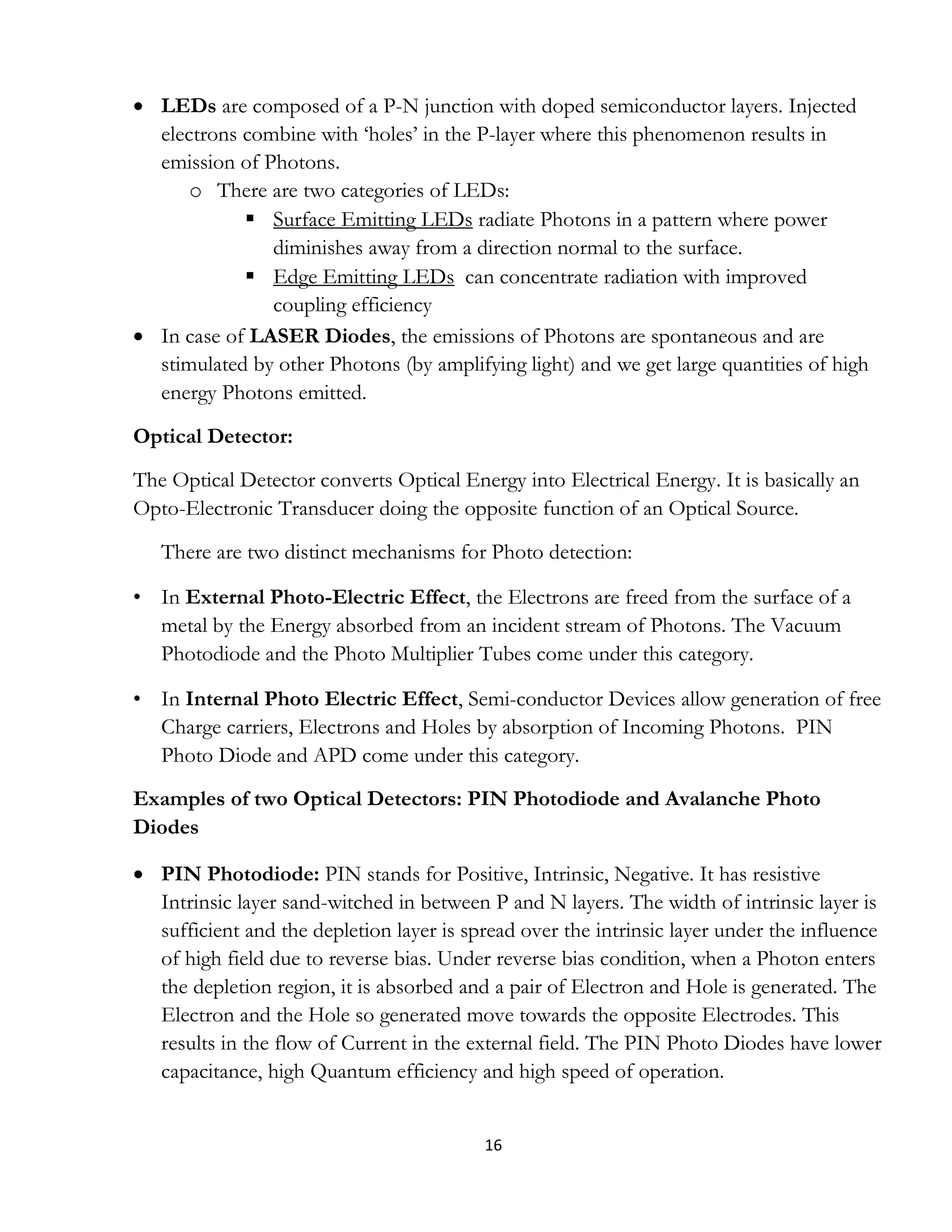
(a)Base Transceiver Station (BTS): It modulates and demodulates baseband
signal. It performs channel processing function. It receives and transmits RF
signal.
(b) Base Station Controller (BSC): It allocates radio resources, call processing,
power controlling, handover processing, voice coding.
(c) Packet Control Function (PCF): They assign supplemental channels for
packet data sessions; maintain reachable state between PDSN and MS; buffer
packets during unavailability of radio resources; and relay packets between MS
and PSDN.
Fig: Structure of CDMA
Network](https://image.slidesharecdn.com/projectreportbasictelecom-160530155957/75/Project-Report-Basic-Telecom-BSNL-24-2048.jpg)


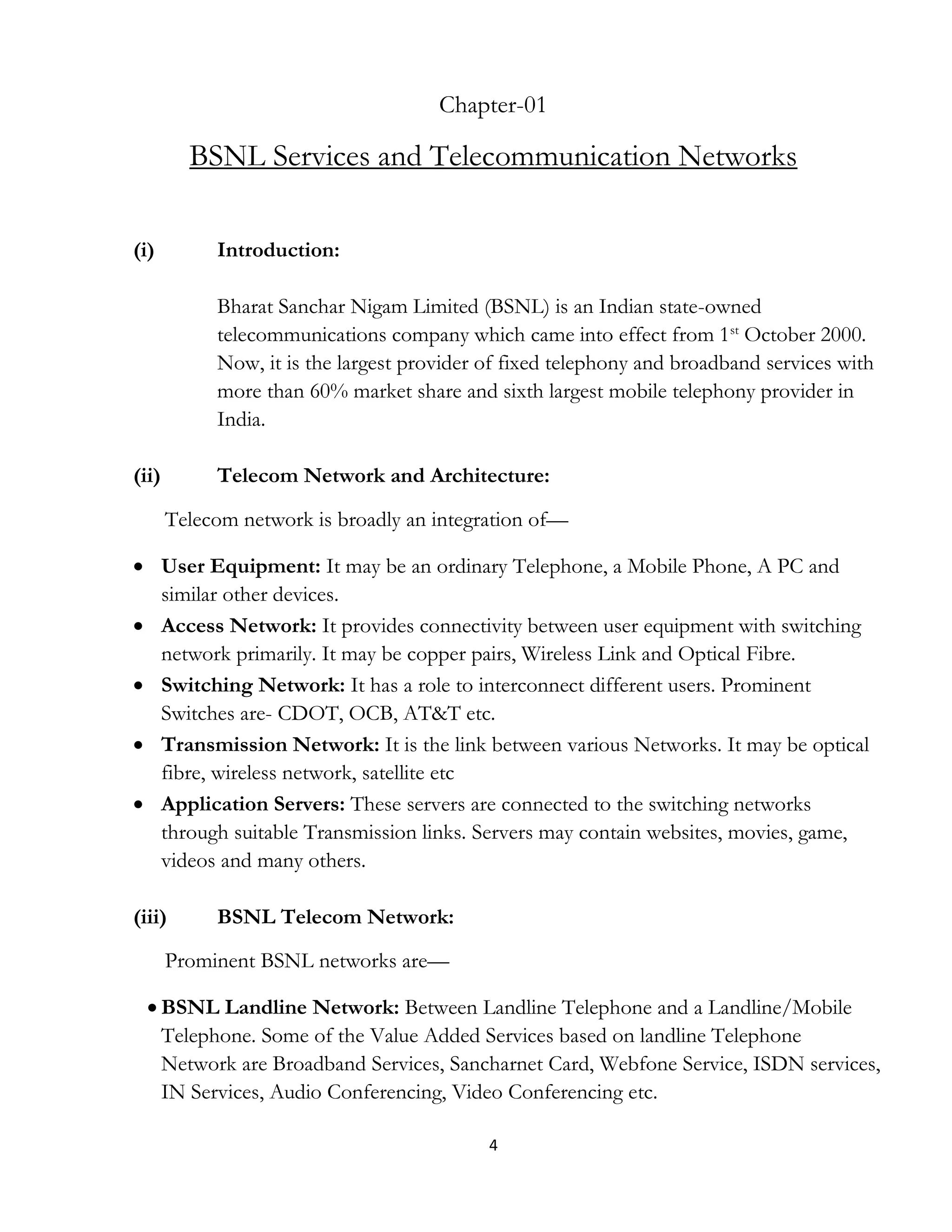
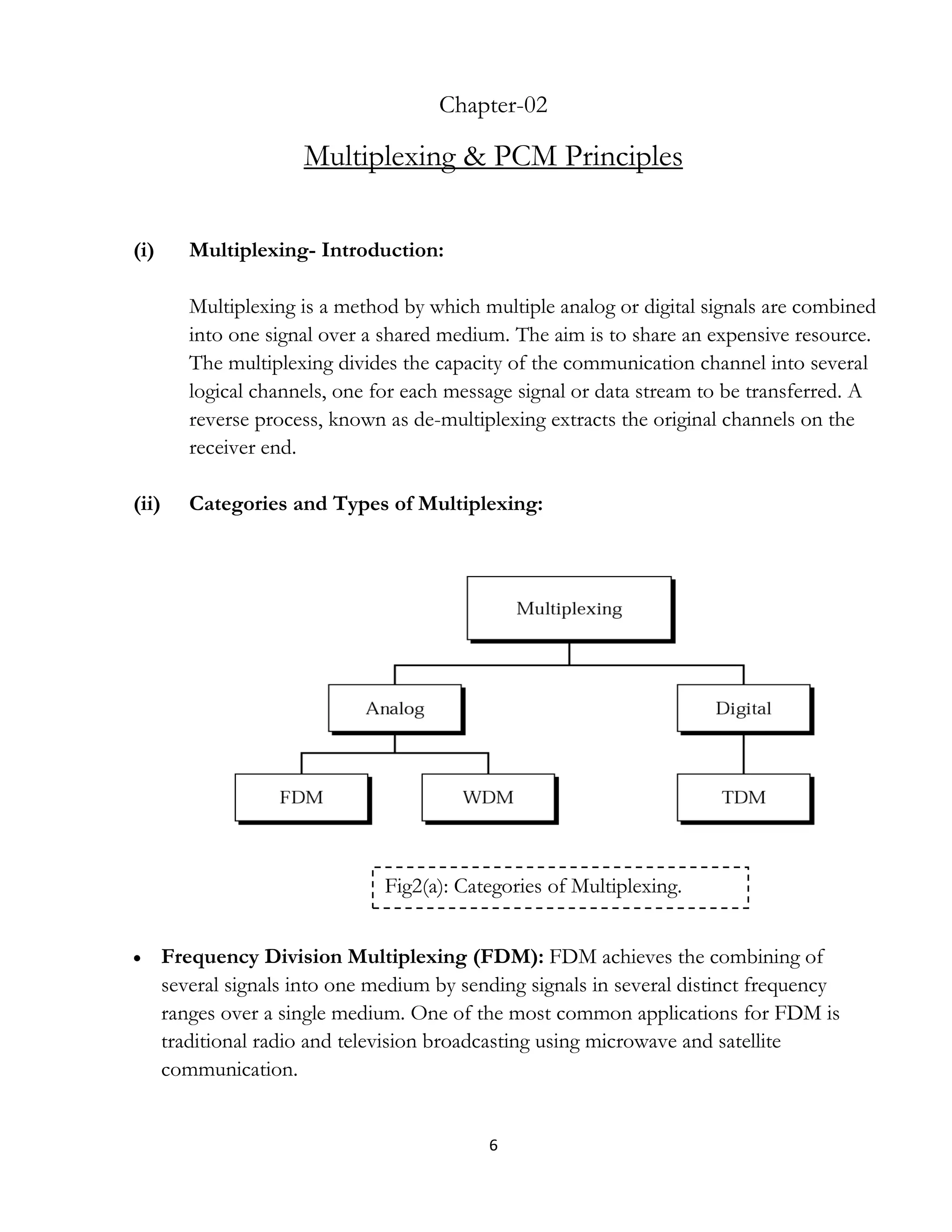
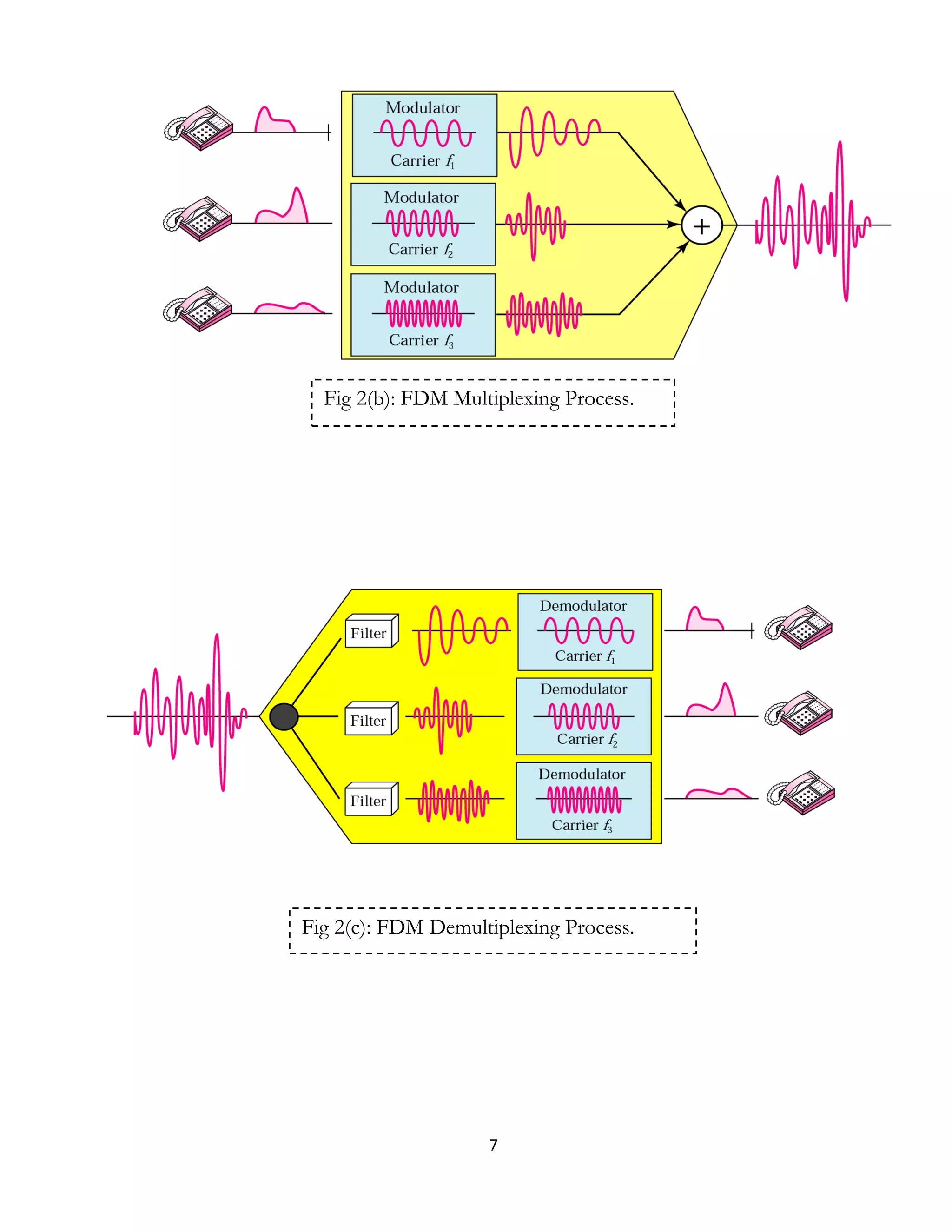
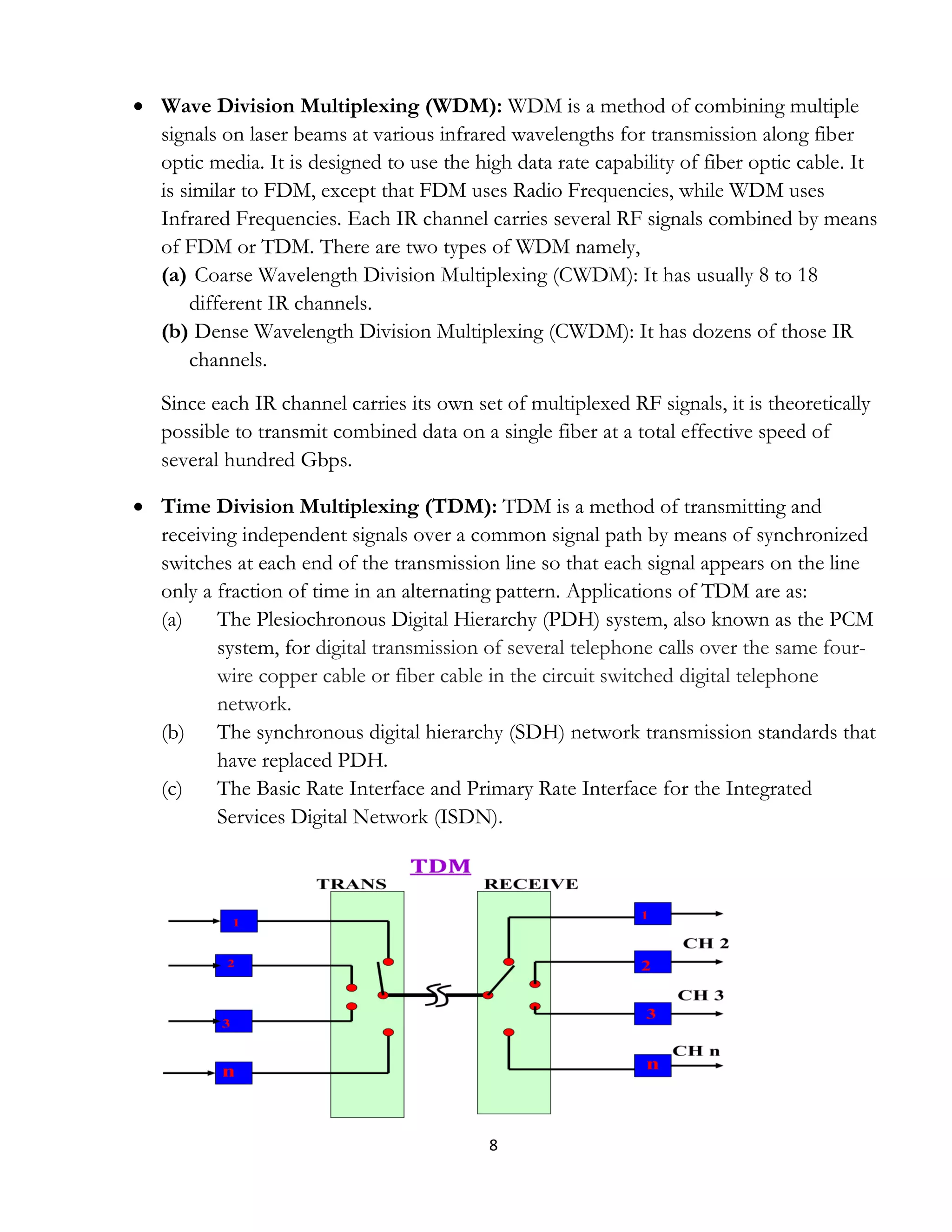
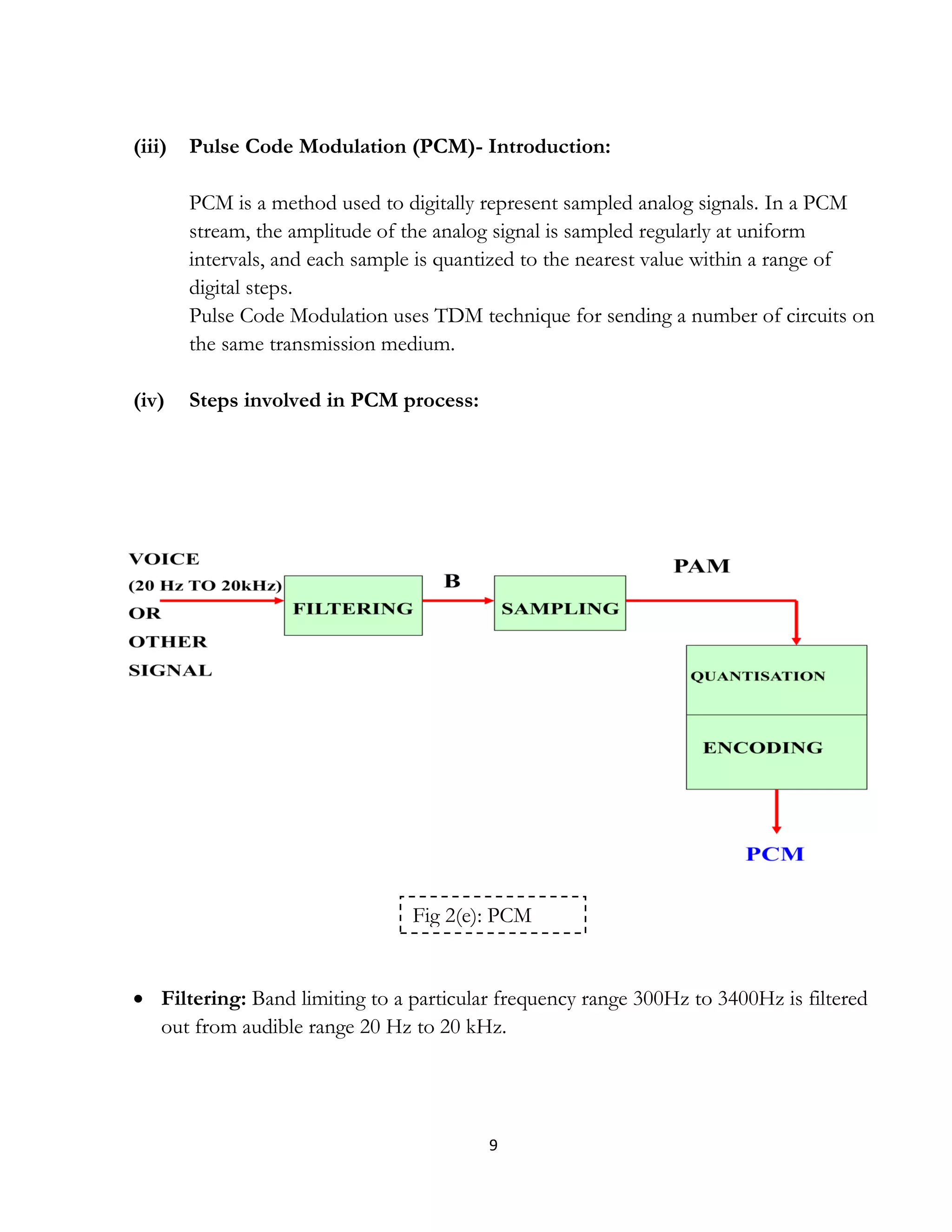
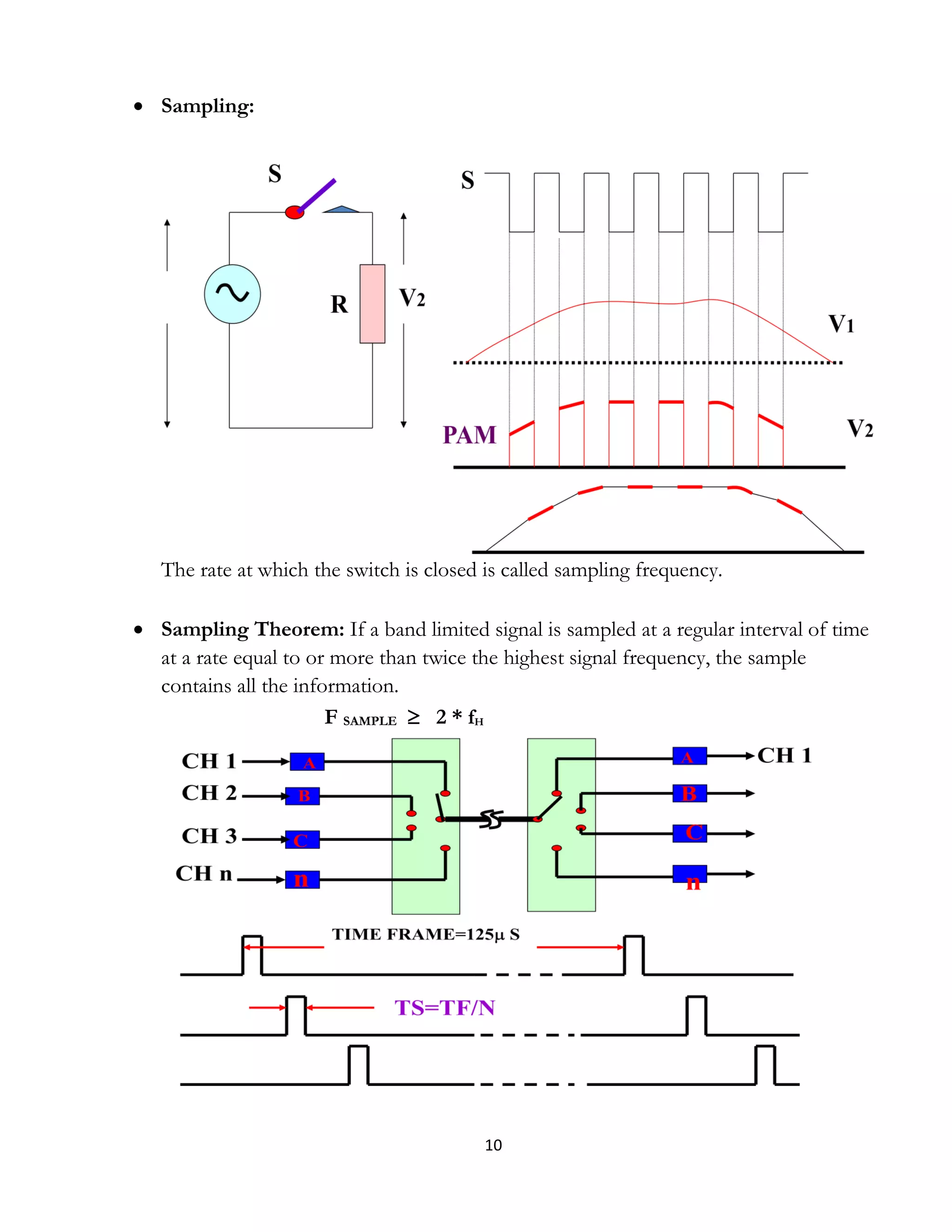
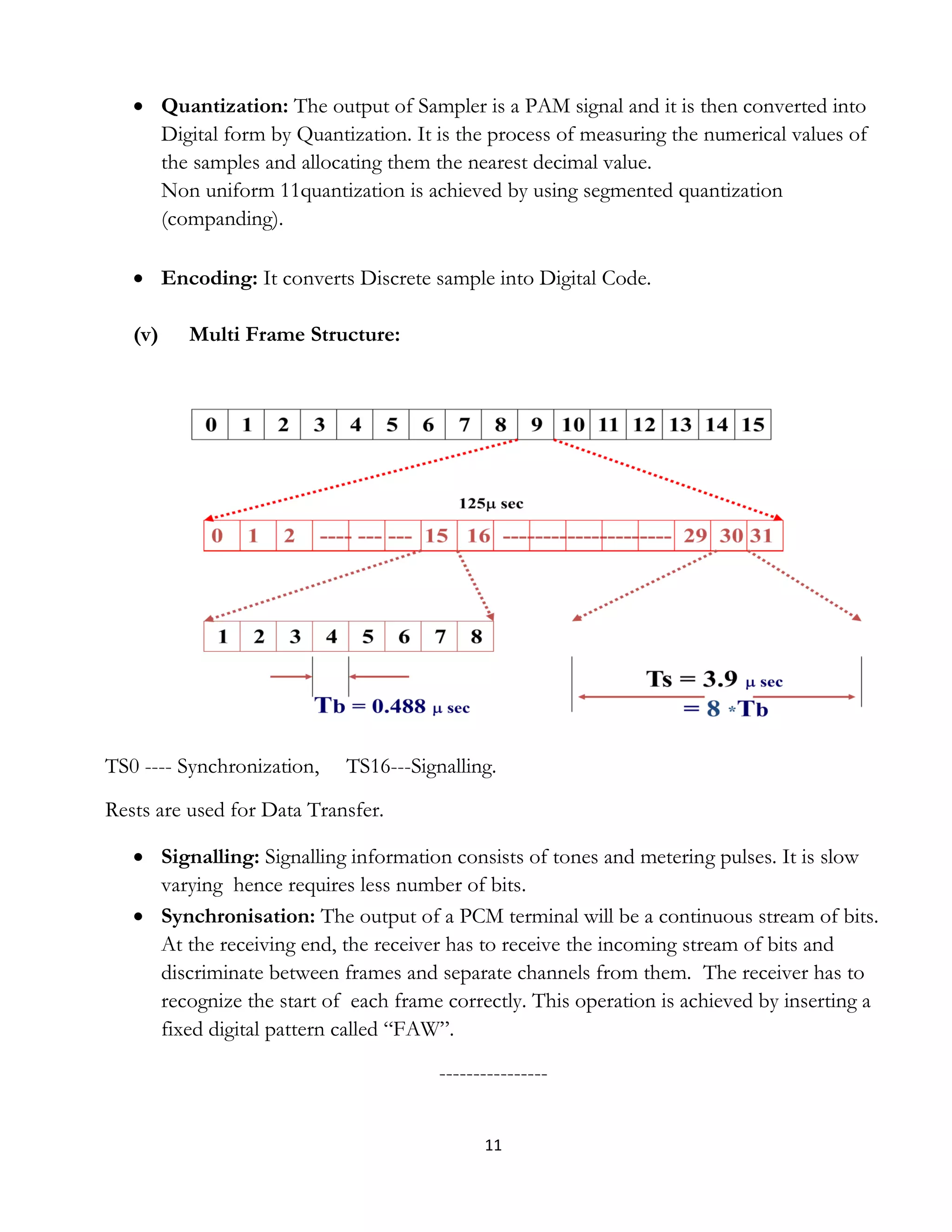
Pankaj KR Purbey underwent a 14-day vocational training in basic telecommunications at RTTC BSNL in Guwahati. The document provides an overview of BSNL services and telecommunication networks in India. It discusses the architecture of telecom networks including user equipment, access networks, switching networks, and transmission networks. It also describes the key networks operated by BSNL including landline, mobile, WLL, internet/broadband, ISDN, and data networks. The document further explains concepts of multiplexing including FDM, WDM, and TDM. It provides details of pulse code modulation techniques involving filtering, sampling, quantization, encoding, and multi-frame structures


