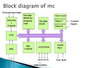
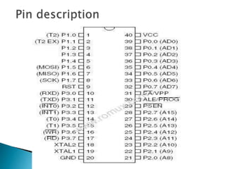
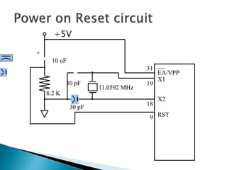
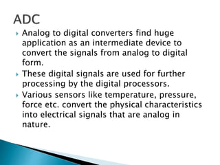
Presentation of Main Project on
“UNDERGROUND CABLE FAULT DISTANCE
LOCATOR”
Presented by
B2C005 AMIT CHAKRABORTY
DEPARTMENT OF ELECTRICAL & ELECTRONICS ENGINEERING
GOVT. COLLEGE OF ENGINEERING KANNUR- 670563
JANUARY 2016
1
 Project overview
 Block diagram
 Power supply
 Microcontroller
 ADC0804
 Relay
 Relay driver
 LCD
 Software requirements
 Schematic & Working of the project
 Advantages
 Applications
 Future scope
 Conclusion
 The project uses the simple concept of OHMs law
where a low DC voltage is applied at the feeder end
through a series resistor.
 The current would vary depending upon the length
of fault of the cable in case there is a short circuit
of LL or 3L or LG etc.
.
 The series resistor voltage drop changes
accordingly which is then fed to an ADC to develop
precise digital data which the programmed
microcontroller would display the same in Kilo
meters.
 The project is assembled with a set of resistors
representing cable length in KMs and fault creation
is made by a set of switches at every known KM to
cross check the accuracy of the same
 The 230V AC supply is first stepped down to 12V
AC using a step down transformer.
 This is then converted to DC using bridge rectifier.
 The AC ripples is filtered out by using a capacitor
and given to the input pin of voltage regulator
7805.
 At output pin of this regulator we get a constant 5V
DC which is used for MC and other ICs in this
project.
 It is a smaller computer
 Has on-chip RAM, ROM, I/O ports...
RAM ROM
I/O
Port
Timer
Serial
COM
Port
Microcontroller
CPU
A single chip
CPU
On-chip
RAM
On-chip
ROM for
program
code
4 I/O Ports
Timer 0
Serial
Port
OSC
Interrup
t
Control
External interrupts
Timer 1
Timer/Counter
Bus
Control
TxD RxDP0 P1 P2 P3
Address/Data
Counter
Inputs
 8K Bytes of In-System Programmable
(ISP) Flash Memory
 4.0V to 5.5V Operating Range
 Fully Static Operation: 0 Hz to 33 MHz
 256 x 8-bit Internal RAM
 32 Programmable I/O Lines
 Three 16-bit Timer/Counters
 Eight Interrupt Sources
 Full Duplex UART Serial Channel
+5V
30 pF
30 pF
8.2 K
10 uF
+
11.0592 MHz
EA/VPP
X1
X2
RST
31
19
18
9
 Analog to digital converters find huge
application as an intermediate device to
convert the signals from analog to digital
form.
 These digital signals are used for further
processing by the digital processors.
 Various sensors like temperature, pressure,
force etc. convert the physical characteristics
into electrical signals that are analog in
nature.
 ADC0804 is a very
commonly used 8-bit
analog to digital
convertor.
 It is a single channel IC,
i.e., it can take only one
analog signal as input.
 Compatible with microcontrollers, access
time is 135ns.
 Logic inputs and outputs meet both MOS
and TTL voltage level specifications.
 Works with 2.5V (LM336) voltage reference.
 On-chip clock generator.
 0V to 5V analog input voltage range with
single 5V supply.
 20-pin molded chip carrier or small outline
package.
 Operates ratio metrically or with 5 VDC, 2.5
VDC, or analog span adjusted voltage
reference.
 A relay is an electrically operated switch.
 Current flowing through the coil of the relay
creates a magnetic field which attracts a
lever and changes the switch contacts.
 The coil current can be on or off so relays
have two switch positions and have double
throw (changeover) switch contacts as
shown in the diagram.
 Relays allow one circuit to switch a second
circuit which can be completely separate from
the first.
 For example a low voltage battery circuit can
use a relay to switch a 230V AC mains circuit.
 There is no electrical connection inside the
relay between the two circuits, the link is
magnetic and mechanical.
 To drive relay through MC ULN2003 relay
driver IC is used
 ULN is Relay driver application
 The ULN2003 is a monolithic high voltage
and high current Darlington transistor arrays.
 It consists of seven NPN Darlington pairs that
features high-voltage outputs with common-
cathode clamp diode for switching inductive
loads.
 The collector-current rating of a single
Darlington pair is 500mA.
 The Darlington pairs may be paralleled for
higher current capability.
 The ULN functions as
an inverter.
 If the logic at input
1B is high then the
output at its
corresponding pin
1C will be low.
 Most common LCDs connected to the microcontrollers are
16x2 and 20x2 displays.
 This means 16 characters per line by 2 lines and 20
characters per line by 2 lines, respectively.
 The standard is referred to as HD44780U, which refers to the
controller chip which receives data from an external source
(and communicates directly with the LCD.
 If an 8-bit data bus is used the LCD will
require 11 data lines(3 control lines plus the
8 lines for the data bus)
 The three control lines are referred to as EN,
RS, and RW
 EN=Enable (used to tell the LCD that you are
sending it data)
 RS=Register Select. When RS=0; data is
treated as a command & When RS=1; data
being sent is text data.
 R/W=Read/Write . When RW=0; the data
written to the LCD & When RW=0; the data
reading to the LCD.
 Keil an ARM Company makes C compilers, macro
assemblers, real-time kernels, debuggers, simulators,
integrated environments, evaluation boards, and
emulators for ARM7/ARM9/Cortex-M3,
XC16x/C16x/ST10, 251, and 8051 MCU families.
 Compilers are programs used to convert a High Level
Language to object code. Desktop compilers produce an
output object code for the underlying microprocessor,
but not for other microprocessors.
 i.e., the programs written in one of the HLL like ‘C’ will
compile the code to run on the system for a particular
processor like x86 (underlying microprocessor in the
computer).
 For example compilers for Dos platform is different from
the Compilers for Unix platform So if one wants to define a
compiler then compiler is a program that translates source
code into object code.
 The project uses a set of resistances in series i.e.
R10,R11,R12,R13 and R17,R16,R14,R21,
R20,R19,R18,R25,R22 as shown in the circuit
diagram, one set for each phase.
 Each series resistors represents the resistance of
the underground cable for a specific distance
thus 4 such resistances in series represent 1-
4kms.
 3 relays are used to common point of their
contacts are grounded while the NO points are
connected to the input of the R17, R21 & R25
being the 3 phase cable input.
 R10 is fed with a series resistor R1 to 5v supply.
The common point of R10 & R1 is given to input
pin of 6 of ADC0804 duely wired as explained
above.
Precise kilometer calculation by underground cable fault detector

Precise kilometer calculation by underground cable fault detector

  • 1.
    Presentation of MainProject on “UNDERGROUND CABLE FAULT DISTANCE LOCATOR” Presented by B2C005 AMIT CHAKRABORTY DEPARTMENT OF ELECTRICAL & ELECTRONICS ENGINEERING GOVT. COLLEGE OF ENGINEERING KANNUR- 670563 JANUARY 2016 1
  • 2.
     Project overview Block diagram  Power supply  Microcontroller  ADC0804  Relay  Relay driver  LCD  Software requirements  Schematic & Working of the project  Advantages  Applications  Future scope  Conclusion
  • 3.
     The projectuses the simple concept of OHMs law where a low DC voltage is applied at the feeder end through a series resistor.  The current would vary depending upon the length of fault of the cable in case there is a short circuit of LL or 3L or LG etc. .
  • 4.
     The seriesresistor voltage drop changes accordingly which is then fed to an ADC to develop precise digital data which the programmed microcontroller would display the same in Kilo meters.  The project is assembled with a set of resistors representing cable length in KMs and fault creation is made by a set of switches at every known KM to cross check the accuracy of the same
  • 7.
     The 230VAC supply is first stepped down to 12V AC using a step down transformer.  This is then converted to DC using bridge rectifier.  The AC ripples is filtered out by using a capacitor and given to the input pin of voltage regulator 7805.  At output pin of this regulator we get a constant 5V DC which is used for MC and other ICs in this project.
  • 8.
     It isa smaller computer  Has on-chip RAM, ROM, I/O ports... RAM ROM I/O Port Timer Serial COM Port Microcontroller CPU A single chip
  • 9.
    CPU On-chip RAM On-chip ROM for program code 4 I/OPorts Timer 0 Serial Port OSC Interrup t Control External interrupts Timer 1 Timer/Counter Bus Control TxD RxDP0 P1 P2 P3 Address/Data Counter Inputs
  • 10.
     8K Bytesof In-System Programmable (ISP) Flash Memory  4.0V to 5.5V Operating Range  Fully Static Operation: 0 Hz to 33 MHz  256 x 8-bit Internal RAM  32 Programmable I/O Lines  Three 16-bit Timer/Counters  Eight Interrupt Sources  Full Duplex UART Serial Channel
  • 12.
    +5V 30 pF 30 pF 8.2K 10 uF + 11.0592 MHz EA/VPP X1 X2 RST 31 19 18 9
  • 13.
     Analog todigital converters find huge application as an intermediate device to convert the signals from analog to digital form.  These digital signals are used for further processing by the digital processors.  Various sensors like temperature, pressure, force etc. convert the physical characteristics into electrical signals that are analog in nature.
  • 14.
     ADC0804 isa very commonly used 8-bit analog to digital convertor.  It is a single channel IC, i.e., it can take only one analog signal as input.
  • 15.
     Compatible withmicrocontrollers, access time is 135ns.  Logic inputs and outputs meet both MOS and TTL voltage level specifications.  Works with 2.5V (LM336) voltage reference.  On-chip clock generator.  0V to 5V analog input voltage range with single 5V supply.  20-pin molded chip carrier or small outline package.  Operates ratio metrically or with 5 VDC, 2.5 VDC, or analog span adjusted voltage reference.
  • 16.
     A relayis an electrically operated switch.  Current flowing through the coil of the relay creates a magnetic field which attracts a lever and changes the switch contacts.  The coil current can be on or off so relays have two switch positions and have double throw (changeover) switch contacts as shown in the diagram.
  • 17.
     Relays allowone circuit to switch a second circuit which can be completely separate from the first.  For example a low voltage battery circuit can use a relay to switch a 230V AC mains circuit.  There is no electrical connection inside the relay between the two circuits, the link is magnetic and mechanical.  To drive relay through MC ULN2003 relay driver IC is used
  • 18.
     ULN isRelay driver application  The ULN2003 is a monolithic high voltage and high current Darlington transistor arrays.  It consists of seven NPN Darlington pairs that features high-voltage outputs with common- cathode clamp diode for switching inductive loads.  The collector-current rating of a single Darlington pair is 500mA.  The Darlington pairs may be paralleled for higher current capability.
  • 19.
     The ULNfunctions as an inverter.  If the logic at input 1B is high then the output at its corresponding pin 1C will be low.
  • 20.
     Most commonLCDs connected to the microcontrollers are 16x2 and 20x2 displays.  This means 16 characters per line by 2 lines and 20 characters per line by 2 lines, respectively.  The standard is referred to as HD44780U, which refers to the controller chip which receives data from an external source (and communicates directly with the LCD.
  • 21.
     If an8-bit data bus is used the LCD will require 11 data lines(3 control lines plus the 8 lines for the data bus)  The three control lines are referred to as EN, RS, and RW  EN=Enable (used to tell the LCD that you are sending it data)  RS=Register Select. When RS=0; data is treated as a command & When RS=1; data being sent is text data.  R/W=Read/Write . When RW=0; the data written to the LCD & When RW=0; the data reading to the LCD.
  • 22.
     Keil anARM Company makes C compilers, macro assemblers, real-time kernels, debuggers, simulators, integrated environments, evaluation boards, and emulators for ARM7/ARM9/Cortex-M3, XC16x/C16x/ST10, 251, and 8051 MCU families.  Compilers are programs used to convert a High Level Language to object code. Desktop compilers produce an output object code for the underlying microprocessor, but not for other microprocessors.
  • 23.
     i.e., theprograms written in one of the HLL like ‘C’ will compile the code to run on the system for a particular processor like x86 (underlying microprocessor in the computer).  For example compilers for Dos platform is different from the Compilers for Unix platform So if one wants to define a compiler then compiler is a program that translates source code into object code.
  • 24.
     The projectuses a set of resistances in series i.e. R10,R11,R12,R13 and R17,R16,R14,R21, R20,R19,R18,R25,R22 as shown in the circuit diagram, one set for each phase.  Each series resistors represents the resistance of the underground cable for a specific distance thus 4 such resistances in series represent 1- 4kms.  3 relays are used to common point of their contacts are grounded while the NO points are connected to the input of the R17, R21 & R25 being the 3 phase cable input.  R10 is fed with a series resistor R1 to 5v supply. The common point of R10 & R1 is given to input pin of 6 of ADC0804 duely wired as explained above.